EP0519997B1 - Roue de coulee refroidie uniformement - Google Patents
Roue de coulee refroidie uniformement Download PDFInfo
- Publication number
- EP0519997B1 EP0519997B1 EP91906317A EP91906317A EP0519997B1 EP 0519997 B1 EP0519997 B1 EP 0519997B1 EP 91906317 A EP91906317 A EP 91906317A EP 91906317 A EP91906317 A EP 91906317A EP 0519997 B1 EP0519997 B1 EP 0519997B1
- Authority
- EP
- European Patent Office
- Prior art keywords
- coolant
- casting
- channels
- products directly
- casting surface
- Prior art date
- Legal status (The legal status is an assumption and is not a legal conclusion. Google has not performed a legal analysis and makes no representation as to the accuracy of the status listed.)
- Expired - Lifetime
Links
- 238000005266 casting Methods 0.000 title claims abstract description 105
- 239000002826 coolant Substances 0.000 claims abstract description 132
- 229910052751 metal Inorganic materials 0.000 claims abstract description 45
- 239000002184 metal Substances 0.000 claims abstract description 45
- 238000012546 transfer Methods 0.000 claims abstract description 20
- 239000000758 substrate Substances 0.000 claims description 34
- 239000007788 liquid Substances 0.000 claims description 19
- 238000000034 method Methods 0.000 claims description 10
- 238000004891 communication Methods 0.000 claims description 4
- 239000007787 solid Substances 0.000 claims description 2
- 239000000155 melt Substances 0.000 abstract description 9
- 238000013461 design Methods 0.000 description 20
- 238000001816 cooling Methods 0.000 description 8
- 230000008901 benefit Effects 0.000 description 5
- 230000001419 dependent effect Effects 0.000 description 4
- 238000005058 metal casting Methods 0.000 description 3
- XLYOFNOQVPJJNP-UHFFFAOYSA-N water Substances O XLYOFNOQVPJJNP-UHFFFAOYSA-N 0.000 description 3
- 229910000831 Steel Inorganic materials 0.000 description 2
- 229910052782 aluminium Inorganic materials 0.000 description 2
- XAGFODPZIPBFFR-UHFFFAOYSA-N aluminium Chemical compound [Al] XAGFODPZIPBFFR-UHFFFAOYSA-N 0.000 description 2
- 230000000694 effects Effects 0.000 description 2
- 238000004519 manufacturing process Methods 0.000 description 2
- 239000000463 material Substances 0.000 description 2
- 238000005096 rolling process Methods 0.000 description 2
- 239000010959 steel Substances 0.000 description 2
- 229910000968 Chilled casting Inorganic materials 0.000 description 1
- 230000002411 adverse Effects 0.000 description 1
- 230000004323 axial length Effects 0.000 description 1
- 238000009835 boiling Methods 0.000 description 1
- 230000008602 contraction Effects 0.000 description 1
- 230000001276 controlling effect Effects 0.000 description 1
- 230000002596 correlated effect Effects 0.000 description 1
- 125000004122 cyclic group Chemical group 0.000 description 1
- 238000009826 distribution Methods 0.000 description 1
- 230000008030 elimination Effects 0.000 description 1
- 238000003379 elimination reaction Methods 0.000 description 1
- 238000003754 machining Methods 0.000 description 1
- 238000005259 measurement Methods 0.000 description 1
- 230000000116 mitigating effect Effects 0.000 description 1
- 230000000737 periodic effect Effects 0.000 description 1
- 230000000704 physical effect Effects 0.000 description 1
- 238000000926 separation method Methods 0.000 description 1
- 238000007711 solidification Methods 0.000 description 1
- 230000008023 solidification Effects 0.000 description 1
- 238000012360 testing method Methods 0.000 description 1
Images

Classifications
-
- B—PERFORMING OPERATIONS; TRANSPORTING
- B22—CASTING; POWDER METALLURGY
- B22D—CASTING OF METALS; CASTING OF OTHER SUBSTANCES BY THE SAME PROCESSES OR DEVICES
- B22D11/00—Continuous casting of metals, i.e. casting in indefinite lengths
- B22D11/06—Continuous casting of metals, i.e. casting in indefinite lengths into moulds with travelling walls, e.g. with rolls, plates, belts, caterpillars
- B22D11/0637—Accessories therefor
- B22D11/068—Accessories therefor for cooling the cast product during its passage through the mould surfaces
- B22D11/0682—Accessories therefor for cooling the cast product during its passage through the mould surfaces by cooling the casting wheel
Definitions
- the invention relates to casting of metal products, particularly strip material, from a molten mass of the metal, such as shown in US 4,865,117.
- a chilled casting drum or wheel is utilized to cast and solidify the strip.
- a thin layer of molten metal is introduced onto the chill surface and the latent heat of the melt flows radially into the wheel, causing solidification.
- the thickness of the strip as well as the microstructure are highly dependent on the cooling rate of the melt. Higher rates of heat transfer to the chill surface occur when the strip is in close intimate contact (adheres) with the surface. A greater amount of heat can be transferred during this time so that thicker, more uniform strip can be produced.
- a non-uniform temperature across and around the casting wheel will also result in thermal distortion of the casting wheel, again potentially leading to a non-uniform cast product.
- the uniformity of the cast strip and the thermal distortion of the casting wheel are both dependent on the configuration of coolant flow and the local coolant temperature in the wheel.
- DE-A-3839110 shows a cooling method for a casting drum wherein cooled flow appears to be through the channels in one direction only and the channels are served by a common inlet on one side of the drum and a common outlet on the other.
- the inclination is indicated to be light so that the orientation still is essentially in parallel to the drum axis.
- the purpose of the inclination is to have the land between two channels bridge the gap of the neighboring channel so as to avoid any unsupported axial zone on the outer shell of the drum. Consequently, the ends of the channels are displaced circumferentially by an amount equal to the channel width plus the land width which leads to an angle of inclination of only a very few degrees.
- the invention comprises a liquid-cooled substrate for casting uniform metal products directly from the melt including a cylindrical casting drum or wheel having an outer circumferential casting surface and a plurality of helical coolant channels extending below the casting surface and in heat transfer relationship with the casting surface and being substantially parallel to each other at an angle of between about 15° and 75° (and preferably between about 45° and 75°) to the drum axis.
- the invention further includes means for circulating a coolant liquid through the coolant channels in either the same direction or in opposite directions in adjacent channels, each of which have distinct advantages.
- the casting channels may extend from near one side to near the other side, wherein each coolant channel communicates with an inlet near one side of the substrate and an outlet near the other side.
- the inlet of each coolant channel is closer to the outlet than it is to the inlet of each adjacent coolant channel.
- the coolant source and coolant dump may be reservoirs located around the axle on both sides of the drum.
- the coolant source and coolant dump may be reservoirs located around the axle on opposite sides of the drum.
- the casting channels may still extend from near one side to near the other side, but the inlets and outlets are all on one side of the casting surface, and coolant flow is in opposite directions in adjacent channels. Adjacent coolant channel pairs are joined in liquid communication on the one side of the casting surface and the coolant liquid is circulated in through a coolant inlet in the first coolant channel near one side of the casting surface and out through a coolant outlet in the second coolant channel near the same side of the casting surface.
- the coolant source and coolant dump may be reservoirs located only on one side of the core.
- the substrate may comprise a cylindrical core body and a separate annular casting shell which fits over the core body.
- the coolant channels may then comprise machined grooves in the casting shell enclosed by the outer surface of the core body or machined grooves in the outer surface of the core body enclosed by the inside surface of the casting shell.
- the invention also includes a process for casting uniform metal products directly from a metal melt by extracting a molten metal layer from an open tundish on an outer cylindrical casting surface of a cylindrical substrate and solidifying the molten metal layer to a solid strip including circulating a coolant liquid through a plurality of adjacent helical coolant channels extending under the casting surface substantially parallel to each other at an angle of between about 15° and 75° (and preferably between about 45° and 75°) to the drum axis.
- the coolant flow may be either in the same direction or in opposite directions in adjacent channels.
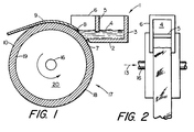
- Figures 1 and 2 show a cross-sectional, side elevation view and a top view of existing apparatus for melt drag or open tundish casting of metal sheet.
- Figure 3 is a plan view of a cylindrical core body used in the inventive liquid-cooled substrate.
- Figure 4 is an expanded section view of the coolant channels along line A-A in Figure 3.
- Figure 5 is a plan view showing an alternative embodiment of the coolant channel configuration according to the invention.
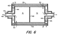
- Figure 6 is a section view along line B-B in Figure 3 showing the inlet and outlet arrangement to feed the coolant channels.
- the invention comprises apparatus for casting of metal products from the melt. It comprises apparatus for uniformly cooling the casting surface and is, therefore, particularly useful for casting wide strip material.
- the thickness and microstructure of strip are particularly dependent on the substrate temperature. Any non-uniformity in temperature across the casting surface will lead to non-uniform heat transfer which imposes thickness and structural variation in the cast strip. Since one of the primary objects of direct cast strip is to cast net-shape and near-net-shape products, the non-uniformity is to be avoided. Non-uniform temperature can also cause differential expansion of the casting surface leading to a distortion of the casting wheel and periodic undulation in the surface. These undulations disrupt the casting mechanics and cause non-uniform thickness in the cast products, especially when a second roller is used in the process to contact and smooth the upper surface of the cast product.
- a cylindrical substrate 17 is made up of a cylindrical core body 20 surrounded by an annular shell 18.
- the shell has an outer cylindrical casting surface 10 and an inner cylindrical surface 19 in contact with the core.
- the substrate 17 is rotated about an axle 16 while the casting surface 10 passes through a pool of molten metal 4 in an open tundish 1.
- the open tundish 1 has a bottom 2, backwall 3 and sidewalls 6.
- the front surface 7 of the bottom and sidewalls adjacent the casting surface 10 are contoured to match the shape of the casting surface.
- a weir 5 can be used to help control the metal depth and turbulence.
- a liquid layer 8 is delivered to the surface 10 where it solidifies to strip 9. The thickness depends on several parameters including the depth of the melt pool and the temperature of the casting surface.
- the casting surface is cooled by circulation of a coolant through cooling channels in the substrate.
- the coolant typically enters and exits at 13 through connections in the axle (to be further described in connection with Figure 6). Water is the preferred coolant.
- the hollow core 20 is shown with parallel cooling channels 25 machined angularly across the core outside surface leaving ribs 26 between channels.
- the layout shown in Figure 3 could be used in practice, but is generally foreshortened to show the concept. In most commercial applications, the core is much longer so that the channels are more helically wrapped around the core.
- End plates 14 close off the channels at the periphery of the core.
- the channels are cut at an angle, ⁇ , of between about 15° and 75° (and preferably between about 45° and 75°) to the drum axis.
- Each coolant channel 25 has a coolant inlet 21a or 21b at one end near one side of the substrate and a coolant outlet 22a or 22b at the other end near the other side of the substrate.
- coolant entering the coolant channel is cooler than that exiting the outlet.
- ⁇ T about 6°C.
- inlet 21a is adjacent outlets 22b and 22c of adjacent channels.
- Figure 3 shows the embodiment wherein the flow in adjacent channels is in opposite directions.
- the same basic design can be used when the flow in all the channels is in the same direction.
- all the inlets will be on one side and all the outlets on the other side.
- the advantage of the opposite flow is the pairing of a warmer outlet region with a cooler inlet region.
- the inlet side coolant is a few degrees cooler than the outlet side, but the short circuit phenomenon is avoided.
- the advantage of flow in the same direction is therefore the elimination of potential hot spots when a particular use results in shell expansion and short circuiting of coolant.
- the selection of flow in the same direction or in opposite direction will depend on the application.
- Uniform temperature depends on controlling the heat transfer coefficient, which depends (among other things) on the coolant velocity.
- the velocity can be altered be the varying the size and length of the channels. But there are constraints on the size of the channels, like the structural integrity of the casting wheel. So, the coolant velocity is more easily controlled by the length of the channels.
- the length of the channels (and therefore the number of channels necessary to cover the surface) are chosen to produce the desired cooling effect.
- the angular configuration of the channels involves a trade off affecting the heat transfer efficiency. Wrapping of long channels across the surface (large ⁇ ) results in fewer channels, higher velocity of coolant (for a given flow rate), and higher heat transfer. But a longer channel has a higher pressure drop between the inlet and outlet of the channel which may contribute to the short circuit phenomenon when the outside shell 18 expands away from the ribs 26 during operation.
- the coolant in a channel may cross over the rib and return to the outlet of the adjacent channel on the side of the substrate from which it came rather than flow down the channel to its own outlet on the other side of the substrate. This, of course, is undesirable and causes hot spots.
- the angle ⁇ is therefore chosen by determining the heat load and designing the channel angle to maximize heat transfer while minimizing short circuiting at the available flow rate.
- the advantage of such design is that the heat load is identical for all channels at all times. Axial channels or other channels not making a complete revolution, are exposed to different heat loads depending on their position relative to the metal strip. In the former designs, the channels are loaded equally on a time-averaged basis, but not instantaneously. Since heat causes changes in the physical properties of the coolant, unbalanced heat load can cause unbalanced flow in the wheel, possibly leading to flow instability and/or local hot spots. Other designs where each channel makes a higher integer number of revolutions would also benefit from the even heat load condition, but machining limitations and coolant velocity and pressure become considerations for long channels.
- a 107 cm wide by 71 cm diameter drum preferably is constructed with 38 channels. Each channel makes 0.997 revolutions and is 247 cm long.
- Figure 4 shows an enlarged section view of the inventive Threaded Coolant Flow substrate core.
- the channels 25 are machined in the surface leaving the ribs 26 between channels.
- Figure 5 shows an alternative embodiment of the invention which allows all the coolant supply apparatus to be located on one side of the substrate.
- the cylindrical core 30 has coolant channel pairs machined into the surface extending in a first channel 31 across the substrate from near one side 38 of the substrate to near the other side 39 of the substrate and a second channel 32 back to near the first side 38.
- the paired first and second channels are in liquid communication near the other side 39.
- the channel pairs may be separated by a shortened rib 33 whereas the pairs are separated from the next pair by the full width ribs 34.
- the channels are again substantially parallel to each other channel and cut at an angle, ⁇ , of greater than about 15° to the core axis.
- Each coolant channel pair communicates with an inlet 35 in the first channel near the one side 38 of the casting surface and an outlet 36 in the second channel near the same one side 38 of the casting surface.
- the direction of coolant flow is shown by arrow 37 from the inlet to the outlet.
- the inlets and outlets are again alternated around the circumference so that the flow across the substrate in each coolant channel leg is opposite the direction of coolant flow in each adjacent coolant channel leg.
- coolant supply reservoirs 50 are defined by end caps 43 and 44 on each end of the hollow core 20. Coolant is supplied as at 45 through an axial conduit to the supply reservoir. Coolant from the supply reservoir flows through inlets 21, through the coolant channels 25 on the substrate surface and then leaves through outlets 22. It then passes into a coolant dump 51 on the side opposite the supply reservoir. The dumps are formed between end caps 44 and a central divider 48 inside the drum. Coolant then leaves the dumps as at 46. Similar supply and dumps are located on each side since inlets and outlets are on both sides.
- supply and return apparatus is similar in nature but, of course, is limited to one side of the substrate.
- a simpler design with a supply reservoir on the one side and the dump on the other side is used.
- a slight throttling of the coolant may be useful for mitigating cavitation by the intimate contact of the coolant with the shell. This can be accomplished, for example, by a slight choking of the outlets (eg. by making the outlets slightly smaller than the inlets) or by the use of a downstream flow-control valve.
- the coolant channels are machined below the casting surface by any known means. It is convenient to have a core body covered with an annular shell. This allows the shell to be removed and replaced by another new casting surface without replacing the core. If the coolant channels are grooves machined in the core, the replacement of the shell saves labor in making new coolant channels. Of course, the grooves could be machined in the inside surface of the shell or both in the shell and the core body.
- the casting wheel is essentially a heat transfer medium. It absorbs the thermal energy released when the molten metal solidifies to form the strip. It then transfers this thermal energy to the coolant. Not only must the casting wheel be capable of transferring large amounts of thermal energy, it must also transfer the heat uniformly with respect to both time and distance. The heat transferred after 100 hours of operation must be the same as after 1 hour of operation for the process to be continuous. And the heat transferred across the casting track width and around the casting wheel circumference must remain stable to achieve a rollable strip profile.
- Casting 1 mm-thick aluminum strip at 60 m/min on a chill wheel generates approximately 1000 BTUs/min/cm of cast width. If 75 cm-wide strip is cast with 125 liters/sec of water as coolant, the coolant temperature will rise less than 4° C. These coolant flow and coolant temperature rise conditions are sufficient to avoid boiling of the coolant along the coolant/shell interface which has been found to reduce heat transfer.
- the caster shell temperature may increase hundreds of degrees during casting.
- Nonuniform heat transfer may yield nonuniform caster shell temperatures which induce elastic distortion in the caster shell.
- the level of distortion is therefore an indirect measure of the uniformity of heat transfer from the caster shell to the coolant.
- coolant channel configurations have been examined to try to make the heat transfer more uniform.
- CCF so-called "Hunter” wheel
- CCF coolant channels running circumferentially around the wheel and may have several inlets and outlets for each channel under the casting surface.
- the inlets of adjacent channels are axially adjacent the inlets of all other channels.
- the outlets are axially adjacent the inlets of all other channels.
- this arrangement results in a cool region followed by a relatively hot region, followed by a relatively cool region, and so on as one proceeds around the circumference.
- a Staggered Coolant Flow or SCF design is shown in US Patent 4,842,040 wherein the nets in the CCF design are offset from the inlets of adjacent channels by a certain angular distance so that a relatively cool inlet is more closely associated with a relatively warmer outlet of adjacent channels than another cooler inlet. This configuration reduces, but does not eliminate the effect of having the inlet and outlet plenums beneath the casting track.
- the coolant enters the wheel along the centerline axis and goes through an internal distribution system into inlet holes which deliver the coolant to channels arranged around the core circumference.
- the channels are separated by lands onto which the caster shell is fit. After traveling through the channels and absorbing heat, the water flows down outlet holes into the core interior and exits the core along its centerline axis.
- the inlets and outlets must be under the casting surface.
- the threaded Coolant Flow design of the present invention wherein the channels are not laid circumferentially, the inlets and outlets are preferably placed outside of the casting surface.
- the SCF wheel showed less distortion because of the circumferential offset in inlets and outlets, but a 0.09 mm variation on this laboratory wheel is magnified on a production wheel and will still result in a product which is commercially unacceptable for rolling in most applications. Moreover, such distortion produces a cyclic change in the separation between the casting surface and the tundish which also negatively affects strip casting behavior and quality.
- the inventive TCF wheel resulted in a distortion of only about 0.05 mm in the same trial.
- the design has reduced distortion considerably and also improved the uniformity of heat transfer, resulting in lower thickness variations which can be correlated with core design.
- Tests on a 100 cm wide caster in a pilot plant environment have shown relatively similar improvements in casting behavior and strip quality with the TCF design, and reduced caster shell distortion.
Landscapes
- Engineering & Computer Science (AREA)
- Mechanical Engineering (AREA)
- Continuous Casting (AREA)
- Braking Arrangements (AREA)
- Mold Materials And Core Materials (AREA)
- Moulds For Moulding Plastics Or The Like (AREA)
Claims (14)
- Substrat uniformément refroidi pour la coulée de produits métalliques uniformes directement à partir d'une masse de métal fondu, comprenant :
un tambour cylindrique à surface de coulée comportant une surface de coulée extérieure cylindrique conductrice de la chaleur et une pluralité de canaux de fluide de refroidissement prévus au-dessous et en relation de transfert de chaleur avec la surface de coulée, lesdits canaux étant sensiblement parallèles les uns aux autres et inclinés suivant un angle compris entre 15 degrés et 75 degrés environ par rapport à l'axe du tambour, et
des moyens de mise en circulation d'un liquide de refroidissement dans les canaux de fluide de refroidissement. - Substrat uniformément refroidi pour la coulée de produits métalliques uniformes directement à partir de la masse de métal fondu suivant la revendication 1, dans lequel les canaux de fluide de refroidissement font un angle d'au moins 45 degrés environ par rapport à l'axe du tambour.
- Substrat uniformément refroidi pour la coulée de produits métalliques uniformes directement à partir de la masse de métal fondu suivant la revendication 2, dans lequel chaque canal de fluide de refroidissement s'étend sur un tour environ du tambour de coulée.
- Substrat uniformément refroidi pour la coulée de produits métalliques uniformes directement à partir de la masse de métal fondu suivant la revendication 1, dans lequel les moyens de mise en circulation d'un liquide de refroidissement dans les canaux de fluide de refroidissement comprennent des moyens de mise en circulation du liquide de refroidissement dans la même direction dans des canaux adjacents.
- Substrat uniformément refroidi pour la coulée de produits métalliques uniformes directement à partir de la masse de métal fondu suivant la revendication 4, dans lequel les moyens de mise en circulation d'un liquide de refroidissement dans les canaux de fluide de refroidissement dans la même direction comprennent une entrée de fluide de refroidissement dans chaque canal de fluide de refroidissement,située près d'un côté de la surface de coulée,et une sortie de fluide de refroidissement située près de l'autre côté de la surface de coulée.
- Substrat uniformément refroidi pour la coulée de produits métalliques uniformes directement à partir de la masse de métal fondu suivant la revendication 5, dans lequel le tambour de coulée comprend :
un noyau cylindrique comportant de multiples entrées et sorties de fluide de refroidissement dans sa surface cylindrique extérieure, et
une enveloppe de coulée annulaire conductrice de la chaleur présentant des surfaces cylindriques à l'intérieur et à l'extérieur, la surface extérieure comprenant la surface de coulée conductrice de la chaleur et la surface intérieure recouvrant la surface cylindrique extérieure du noyau et coopérant avec celle-ci pour définir la pluralité de canaux de fluide de refroidissement s'étendant en travers de la surface de coulée. - Substrat uniformément refroidi pour la coulée de produits métalliques uniformes directement à partir de la masse de métal fondu suivant la revendication 1, dans lequel les moyens de mise en circulation d'un liquide de refroidissement dans les canaux de fluide de refroidissement comprennent des moyens de mise en circulation du liquide de refroidissement dans des directions opposées dans les canaux adjacents.
- Substrat uniformément refroidi pour la coulée de produits métalliques uniformes directement à partir de la masse de métal fondu suivant la revendication 7, dans lequel les moyens de mise en circulation d'un liquide de refroidissement dans des premier et deuxième canaux de fluide de refroidissement adjacents, dans les directions opposées, comprennent :
une entrée de fluide de refroidissement dans le premier canal de fluide de refroidissement près d'un côté de la surface de coulée, et une sortie de fluide de refroidissement du deuxième canal de fluide de refroidissement près du même côté de la surface de coulée, et
des moyens de jonction des premier et deuxième canaux de fluide de refroidissement en communication de liquide, ces moyens étant situés sur ledit autre côté de la surface de coulée. - Substrat uniformément refroidi pour la coulée de produits métalliques uniformes directement à partir de la masse de métal fondu suivant la revendication 8, dans lequel les canaux de fluide de refroidissement font un angle d'au moins 45 degrés environ par rapport à l'axe du tambour.
- Substrat uniformément refroidi pour la coulée de produits métalliques uniformes directement à partir de la masse de métal fondu suivant la revendication 8, dans lequel le tambour de coulée comprend :
un noyau cylindrique comportant de multiples entrées et sorties de fluide de refroidissement dans sa surface cylindrique extérieure, et
une enveloppe de coulée annulaire conductrice de la chaleur présentant des surfaces cylindriques intérieure et extérieure, la surface extérieure constituant la surface de coulée conductrice de la chaleur et la surface intérieure recouvrant la surface cylindrique extérieure du noyau et coopérant avec celle-ci pour définir la pluralité de canaux de fluide de refroidissement adjacents s'étendant en travers de la surface de coulée. - Procédé pour la coulée de produits métalliques uniformes directement à partir d'une masse de métal fondu, par extraction d'une couche de métal fondu, à partir d'un bassin de coulée ouvert, sur une surface de coulée cylindrique extérieure d'un substrat cylindrique, et solidification de la couche de métal fondu en une bande solide, dans lequel le perfectionnement comprend :
la mise en circulation d'un liquide de refroidissement dans une pluralité de canaux de fluide de refroidissement adjacents s'étendant sous la surface de coulée sensiblement parallèlement les uns aux autres suivant un angle compris entre 15 degrés et 75 degrés environ par rapport à l'axe du tambour. - Procédé pour la coulée de produits métalliques uniformes directement à partir d'une masse de métal fondu suivant la revendication 11, qui comprend en outre la mise en circulation du liquide de refroidissement dans des canaux adjacents, dans la même direction.
- Procédé pour la coulée de produits métalliques uniformes directement à partir d'une masse de métal fondu suivant la revendication 11, qui comprend en outre la mise en circulation du liquide de refroidissement dans des canaux adjacents et des directions opposées.
- Procédé pour la coulée de produits métalliques uniformes directement à partir d'une masse de métal fondu suivant la revendication 13, qui comprend en outre :
la jonction des premier et deuxième canaux de fluide de refroidissement adjacents, en communication de liquide,près d'un côté de la surface de coulée, et
la mise en circulation du liquide de refroidissement dans une entrée de fluide de refroidissement dans le premier canal de fluide de refroidissement, près de l'autre côté de la surface de coulée, et la sortie du liquide par une sortie de fluide de refroidissement du deuxième canal de fluide de refroidissement près du même autre côté de la surface de coulée.
Applications Claiming Priority (3)
| Application Number | Priority Date | Filing Date | Title |
|---|---|---|---|
| US494648 | 1990-03-16 | ||
| US07/494,648 US4993478A (en) | 1990-03-16 | 1990-03-16 | Uniformly-cooled casting wheel |
| PCT/US1991/001645 WO1991013709A2 (fr) | 1990-03-16 | 1991-03-12 | Roue de coulee refroidie uniformement |
Publications (2)
| Publication Number | Publication Date |
|---|---|
| EP0519997A1 EP0519997A1 (fr) | 1992-12-30 |
| EP0519997B1 true EP0519997B1 (fr) | 1994-11-30 |
Family
ID=23965374
Family Applications (1)
| Application Number | Title | Priority Date | Filing Date |
|---|---|---|---|
| EP91906317A Expired - Lifetime EP0519997B1 (fr) | 1990-03-16 | 1991-03-12 | Roue de coulee refroidie uniformement |
Country Status (7)
| Country | Link |
|---|---|
| US (1) | US4993478A (fr) |
| EP (1) | EP0519997B1 (fr) |
| JP (1) | JPH05505767A (fr) |
| AT (1) | ATE114520T1 (fr) |
| CA (1) | CA2078334A1 (fr) |
| DE (1) | DE69105492T2 (fr) |
| WO (1) | WO1991013709A2 (fr) |
Families Citing this family (6)
| Publication number | Priority date | Publication date | Assignee | Title |
|---|---|---|---|---|
| IT1290603B1 (it) * | 1997-05-02 | 1998-12-10 | Voest Alpine Ind Anlagen | Cilindro di colata |
| US6474402B1 (en) * | 1999-07-02 | 2002-11-05 | Armco Inc. | Segmented roll for casting metal strip |
| DE60130339T2 (de) * | 2000-07-19 | 2008-06-12 | Nippon Steel Corp. | Zweirollen-stranggiessmaschiene |
| FR2960815B1 (fr) * | 2010-06-02 | 2012-05-25 | Jean Pierre Darlet | Ensemble de refroidissement d'un film en matiere synthetique |
| CN104368605A (zh) * | 2014-11-19 | 2015-02-25 | 辽宁科技大学 | 一种适用于铸轧薄宽板带的铸轧辊冷却水道 |
| WO2020049343A1 (fr) * | 2018-09-07 | 2020-03-12 | Arcelormittal | Rouleau de refroidissement magnétique |
Family Cites Families (5)
| Publication number | Priority date | Publication date | Assignee | Title |
|---|---|---|---|---|
| DE481365C (de) * | 1926-11-07 | 1929-08-20 | Herzogenrather Glaswerke Biche | Walze zum Auswalzen von geschmolzenem Glase |
| CH429042A (de) * | 1965-03-09 | 1967-01-31 | Prolizenz Ag | Walze für das Giesswalzen von Metall |
| DE3231433C2 (de) * | 1982-08-20 | 1985-07-11 | Mannesmann AG, 4000 Düsseldorf | Innengekühlte Stütz- und/oder Transportwalze und Verfahren zu ihrer Herstellung |
| JPS5966954A (ja) * | 1982-10-08 | 1984-04-16 | Kawasaki Steel Corp | 急冷薄帯製造用ロ−ル |
| JPH07121440B2 (ja) * | 1987-11-19 | 1995-12-25 | 株式会社日立製作所 | 双ロール式連続鋳造装置 |
-
1990
- 1990-03-16 US US07/494,648 patent/US4993478A/en not_active Expired - Fee Related
-
1991
- 1991-03-12 CA CA002078334A patent/CA2078334A1/fr not_active Abandoned
- 1991-03-12 JP JP91506211A patent/JPH05505767A/ja active Pending
- 1991-03-12 AT AT91906317T patent/ATE114520T1/de not_active IP Right Cessation
- 1991-03-12 EP EP91906317A patent/EP0519997B1/fr not_active Expired - Lifetime
- 1991-03-12 WO PCT/US1991/001645 patent/WO1991013709A2/fr active IP Right Grant
- 1991-03-12 DE DE69105492T patent/DE69105492T2/de not_active Expired - Fee Related
Also Published As
| Publication number | Publication date |
|---|---|
| ATE114520T1 (de) | 1994-12-15 |
| WO1991013709A3 (fr) | 1991-10-31 |
| DE69105492D1 (de) | 1995-01-12 |
| US4993478A (en) | 1991-02-19 |
| EP0519997A1 (fr) | 1992-12-30 |
| WO1991013709A2 (fr) | 1991-09-19 |
| DE69105492T2 (de) | 1995-04-06 |
| JPH05505767A (ja) | 1993-08-26 |
| CA2078334A1 (fr) | 1991-09-17 |
Similar Documents
| Publication | Publication Date | Title |
|---|---|---|
| US3780789A (en) | Apparatus for the vertical multiple continuous casting of aluminum and aluminum alloys | |
| CN107000043B (zh) | 用于通过控制辊凸度而连续地铸造铸带的方法和装置 | |
| JP3081879B2 (ja) | 1ロールでまたは2ロール間で連続鋳造するための装置のためのロール | |
| CA1201269A (fr) | Tambour pour machine de coulee continue | |
| EP0664173B1 (fr) | Dispositif et procédé de coulée continue entre deux rouleaux | |
| JPS6051933B2 (ja) | 金属ストリップ連続鋳造の装置および方法 | |
| EP0519997B1 (fr) | Roue de coulee refroidie uniformement | |
| US10722940B2 (en) | Method for casting metal strip with edge control | |
| KR20140029361A (ko) | 쌍롤식 연속주조장치 | |
| JP4263803B2 (ja) | 鋼ストリップ鋳造用アーバレス鋳造ロール及び鋼ストリップ連続鋳造装置 | |
| EP0407978B1 (fr) | Réglage de la flexion dans une machine de coulée entre rouleaux | |
| KR20140005094A (ko) | 차단 요소, 롤 라인, 및 연속주조장치 | |
| JPH082483B2 (ja) | 薄板連続鋳造設備のモールドロール | |
| US2850776A (en) | Roll constructions for continuous casting machines | |
| JPH0218181B2 (fr) | ||
| US3318369A (en) | Cooling system for casting wheel | |
| KR19980019028A (ko) | 금속 스트립 연속 주조장치 및 그 방법 | |
| US6776216B1 (en) | Casting wheel | |
| JPS58209452A (ja) | ロ−ル鋳造機 | |
| US4421155A (en) | Machine duplicatable, direct chill flat ingot casting mold with controlled corner water and adjustable crown forming capability | |
| EP0244257B1 (fr) | Système de refroidissement pour machines de coulée continue de métal | |
| JPH06590A (ja) | 双ロール連鋳機及びそのロール冷却方法 | |
| JPH03297541A (ja) | 連続鋳造設備用モールド | |
| JPS5847541A (ja) | 薄板製造装置 | |
| SU1100243A1 (ru) | Валок-кристаллизатор |
Legal Events
| Date | Code | Title | Description |
|---|---|---|---|
| PUAI | Public reference made under article 153(3) epc to a published international application that has entered the european phase |
Free format text: ORIGINAL CODE: 0009012 |
|
| AK | Designated contracting states |
Kind code of ref document: A1 Designated state(s): AT BE CH DE DK ES FR GB GR IT LI LU NL SE |
|
| 17P | Request for examination filed |
Effective date: 19920915 |
|
| 17Q | First examination report despatched |
Effective date: 19940119 |
|
| RAP1 | Party data changed (applicant data changed or rights of an application transferred) |
Owner name: BATTELLE MEMORIAL INSTITUTE |
|
| GRAA | (expected) grant |
Free format text: ORIGINAL CODE: 0009210 |
|
| AK | Designated contracting states |
Kind code of ref document: B1 Designated state(s): AT BE CH DE DK ES FR GB GR IT LI LU NL SE |
|
| PG25 | Lapsed in a contracting state [announced via postgrant information from national office to epo] |
Ref country code: GR Free format text: LAPSE BECAUSE OF FAILURE TO SUBMIT A TRANSLATION OF THE DESCRIPTION OR TO PAY THE FEE WITHIN THE PRESCRIBED TIME-LIMIT Effective date: 19941130 Ref country code: DK Effective date: 19941130 |
|
| REF | Corresponds to: |
Ref document number: 114520 Country of ref document: AT Date of ref document: 19941215 Kind code of ref document: T |
|
| REF | Corresponds to: |
Ref document number: 69105492 Country of ref document: DE Date of ref document: 19950112 |
|
| ITF | It: translation for a ep patent filed | ||
| ET | Fr: translation filed | ||
| PGFP | Annual fee paid to national office [announced via postgrant information from national office to epo] |
Ref country code: DK Payment date: 19950213 Year of fee payment: 5 |
|
| PGFP | Annual fee paid to national office [announced via postgrant information from national office to epo] |
Ref country code: ES Payment date: 19950309 Year of fee payment: 5 |
|
| PG25 | Lapsed in a contracting state [announced via postgrant information from national office to epo] |
Ref country code: ES Free format text: LAPSE BECAUSE OF FAILURE TO SUBMIT A TRANSLATION OF THE DESCRIPTION OR TO PAY THE FEE WITHIN THE PRESCRIBED TIME-LIMIT Effective date: 19950313 |
|
| PLBE | No opposition filed within time limit |
Free format text: ORIGINAL CODE: 0009261 |
|
| STAA | Information on the status of an ep patent application or granted ep patent |
Free format text: STATUS: NO OPPOSITION FILED WITHIN TIME LIMIT |
|
| 26N | No opposition filed | ||
| PGFP | Annual fee paid to national office [announced via postgrant information from national office to epo] |
Ref country code: SE Payment date: 19970213 Year of fee payment: 7 Ref country code: FR Payment date: 19970213 Year of fee payment: 7 |
|
| PGFP | Annual fee paid to national office [announced via postgrant information from national office to epo] |
Ref country code: AT Payment date: 19970217 Year of fee payment: 7 |
|
| PGFP | Annual fee paid to national office [announced via postgrant information from national office to epo] |
Ref country code: NL Payment date: 19970218 Year of fee payment: 7 Ref country code: CH Payment date: 19970218 Year of fee payment: 7 |
|
| PGFP | Annual fee paid to national office [announced via postgrant information from national office to epo] |
Ref country code: DE Payment date: 19970225 Year of fee payment: 7 |
|
| PGFP | Annual fee paid to national office [announced via postgrant information from national office to epo] |
Ref country code: GB Payment date: 19970226 Year of fee payment: 7 |
|
| PGFP | Annual fee paid to national office [announced via postgrant information from national office to epo] |
Ref country code: BE Payment date: 19970317 Year of fee payment: 7 |
|
| PGFP | Annual fee paid to national office [announced via postgrant information from national office to epo] |
Ref country code: LU Payment date: 19970403 Year of fee payment: 7 |
|
| PG25 | Lapsed in a contracting state [announced via postgrant information from national office to epo] |
Ref country code: LU Free format text: LAPSE BECAUSE OF NON-PAYMENT OF DUE FEES Effective date: 19980312 Ref country code: GB Free format text: LAPSE BECAUSE OF NON-PAYMENT OF DUE FEES Effective date: 19980312 Ref country code: AT Free format text: LAPSE BECAUSE OF NON-PAYMENT OF DUE FEES Effective date: 19980312 |
|
| PG25 | Lapsed in a contracting state [announced via postgrant information from national office to epo] |
Ref country code: SE Free format text: LAPSE BECAUSE OF NON-PAYMENT OF DUE FEES Effective date: 19980313 |
|
| PG25 | Lapsed in a contracting state [announced via postgrant information from national office to epo] |
Ref country code: LI Free format text: LAPSE BECAUSE OF NON-PAYMENT OF DUE FEES Effective date: 19980331 Ref country code: FR Free format text: THE PATENT HAS BEEN ANNULLED BY A DECISION OF A NATIONAL AUTHORITY Effective date: 19980331 Ref country code: CH Free format text: LAPSE BECAUSE OF NON-PAYMENT OF DUE FEES Effective date: 19980331 Ref country code: BE Free format text: LAPSE BECAUSE OF NON-PAYMENT OF DUE FEES Effective date: 19980331 |
|
| BERE | Be: lapsed |
Owner name: BATTELLE MEMORIAL INSTITUTE Effective date: 19980331 |
|
| PG25 | Lapsed in a contracting state [announced via postgrant information from national office to epo] |
Ref country code: NL Free format text: LAPSE BECAUSE OF NON-PAYMENT OF DUE FEES Effective date: 19981001 |
|
| GBPC | Gb: european patent ceased through non-payment of renewal fee |
Effective date: 19980312 |
|
| REG | Reference to a national code |
Ref country code: CH Ref legal event code: PL |
|
| NLV4 | Nl: lapsed or anulled due to non-payment of the annual fee |
Effective date: 19981001 |
|
| PG25 | Lapsed in a contracting state [announced via postgrant information from national office to epo] |
Ref country code: DE Free format text: LAPSE BECAUSE OF NON-PAYMENT OF DUE FEES Effective date: 19981201 |
|
| EUG | Se: european patent has lapsed |
Ref document number: 91906317.2 |
|
| REG | Reference to a national code |
Ref country code: FR Ref legal event code: ST |
|
| PG25 | Lapsed in a contracting state [announced via postgrant information from national office to epo] |
Ref country code: IT Free format text: LAPSE BECAUSE OF NON-PAYMENT OF DUE FEES;WARNING: LAPSES OF ITALIAN PATENTS WITH EFFECTIVE DATE BEFORE 2007 MAY HAVE OCCURRED AT ANY TIME BEFORE 2007. THE CORRECT EFFECTIVE DATE MAY BE DIFFERENT FROM THE ONE RECORDED. Effective date: 20050312 |