EP0519652B1 - Doppel V-Bett Strickmaschine - Google Patents
Doppel V-Bett Strickmaschine Download PDFInfo
- Publication number
- EP0519652B1 EP0519652B1 EP92305389A EP92305389A EP0519652B1 EP 0519652 B1 EP0519652 B1 EP 0519652B1 EP 92305389 A EP92305389 A EP 92305389A EP 92305389 A EP92305389 A EP 92305389A EP 0519652 B1 EP0519652 B1 EP 0519652B1
- Authority
- EP
- European Patent Office
- Prior art keywords
- needle
- bed
- plates
- knitting machine
- plate
- Prior art date
- Legal status (The legal status is an assumption and is not a legal conclusion. Google has not performed a legal analysis and makes no representation as to the accuracy of the status listed.)
- Expired - Lifetime
Links
Images


Classifications
-
- D—TEXTILES; PAPER
- D04—BRAIDING; LACE-MAKING; KNITTING; TRIMMINGS; NON-WOVEN FABRICS
- D04B—KNITTING
- D04B15/00—Details of, or auxiliary devices incorporated in, weft knitting machines, restricted to machines of this kind
- D04B15/10—Needle beds
Definitions
- the present invention relates to a double V bed knitting machine in which a first pair of needle beds which converge at one end are opposed to a second pair of needle beds which converge at the adjacent ends.
- a V bed knitting machine in which a needle bed having heads opposed at an angle is provided above a pair of needle beds having heads opposed at an angle.
- an upper bed is supported on a lower bed symmetrically to left and right, and the lower bed is mounted and supported at both left and right ends on a frame so as not to impede a reciprocating movement of a carriage which supports a lock for operating a needle of the lower bed. Therefore, it can be expected that the needle bed will flex downwards in the central portion thereof, a tail of the needle bed will lower and an advancing direction of the needle is upwardly displaced.
- a supporting member for the upper needle bed is provided on the carriage so that as the carriage moves the needle bed is always maintained at a predetermined position by a roller provided on the supporting member.
- GB-A-2 000 202 describes a needle bed for a flat bed knitting machine which is assembled from two sets of plate-like webs of different heights arranged alternately to form arcuate needle tracks therebetween.
- the arcuate tracks receive curved needles with the bases of the needle beds being horizontal.
- FR-A-1098776 describes a knitting machine which again utilises plates of different heights to guide and separate the needles.
- the plates can here be easily removed for replacement or repair.
- FR-A-2620137 describes a knitting machine having four needle beds.
- the two facing lower beds are supported on a chassis, with their upper ends set at 90° to each other.
- the two facing upper beds are supported above the lower beds by means of two arms so that the beds lie at an angle of 5-10° to the horizontal.
- FR-A-1073501 describes another knitting machine in which a pair of auxiliary needle beds are positioned above a first pair of needle beds, here with the first pair set at 90° to each other and with the auxiliary pair set horizontally.
- a double V bed knitting machine comprising:
- the needle grooves of the lower needle bed are formed between the lower needle plates.
- the lower needle plates constitute side walls of the needle grooves and extend upwards, the extended portions serving as the supporting means for the upper needle bed.
- the base of the upper needle bed is supported by the supporting means and is supported and fixed by a fixing means.
- the fixing means may comprise a wedge-like head and a wedge-like notch provided on the lower surface of the upper needle bed base, and preferably held by a notch provided in an upper edge of the lower needle plate and a wedge-like end of a stop member provided on the upper edge end of the lower needle plate.
- the stop member is tightened by a tightening bolt whereby the lower needle plate and the upper needle bed base are integrally fixed.
- At least some of said lower needle plates extend upwards to form upper needle groove walls, needle plate spacers are held between said upper needle groove walls, and the upper needle bed is constituted by the upper needle groove walls and the needle plate spacers.
- portions of the needle plates fitted in the needle plate grooves provided in the lower needle bed base integrate the needle plates of the upper needle bed with the needle plates of the lower needle bed.
- the spacing between the needle plates which are adjacent to each other is constant, and the upper surfaces of the needle plate spacers constitute the bottoms of the needle grooves to receive needles.
- the upper and lower needle beds are constructed to be integral and the angle formed therebetween is always constant.
- Fig. 1 is a schematic side view of the whole structure of a first embodiment of knitting machine of the present invention, showing only one side of a centre line.
- Figs. 2a and 2b show a lower needle bed base, Fig. 2a being a longitudinal side view and Fig. 2b being an enlarged plan view of a head.
- Figs. 3a, 3b and 3c show a side view and a sectional view of a lower needle plate, Fig. 3a showing an example having an upper needle bed base supporting member, Fig. 3b showing an example having no upper needle bed base supporting member, and Fig. 3c being a sectional view taken on line C-C of Fig. 3a.
- Figs. 4a and 4b show an upper needle bed base, Fig. 4a being a longitudinal side view, and Fig. 4b being an enlarged plan view of a head.
- Fig. 5a is a side view of an upper needle plate
- Fig. 5b is a front view of the same.
- Fig. 6 is a sectional view taken on line VI-VI of Fig. 9.
- Fig. 8 is a sectional view taken on line VIII-VIII of Fig. 9.
- Fig. 9 is a sectional view taken on line IX-IX of Fig. 6.
- Figs. 10a and 10b show a sinker jack, Fig. 10a being a side view, and Fig. 10b being a bottom view.
- Fig. 11 is a side view of a sinker jack.
- Fig. 12 is a side view of a sinker space.
- Figs. 13a, 13b and 13c show a knockover bit, Fig. 13a being a plan view, Fig. 13b being a side view, and Fig. 13c being a rear view.
- Fig. 14 is a schematic side view of the whole structure of another embodiment of knitting machine in accordance with the invention, showing only one side of a centre line.
- Fig. 15a is a side view of a needle plate
- Fig. 15b is a sectional view taken on line B-B of Fig. 15a.
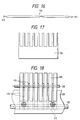
- Fig. 16 is a side view of a needle plate spacer.
- Fig. 17 is a plan view of a continuous ] -shaped comb.
- Fig. 18 is a front view of a beam fixing portion.
- Fig. 19 is a sectional view taken on line XIX-XIX of Fig. 20.
- Fig. 20 is a sectional view taken on line XX-XX of Fig. 19.
- Figs. 21a and 21b show a sinker jack, Fig. 21a being a side view, and Fig. 21b being a bottom view.
- Fig. 22 is a side view of a sinker jack.
- Fig. 23 is a side view of a sinker spacer.
- the knitting machine according to the present invention is a knitting machine based upon a 4-bed system in which an upper needle bed 2 is supported above a lower needle bed 1 with the tops of the beds set at an angle with respect to each other.
- the machine is symmetrical to left and right about a centre line X-X which passes through a tooth portion towards which the tops of the needle beds 1 and 2 converge (see Fig. 1).
- the upper needle bed 2 is supported by a lower needle plate 3A of the lower needle bed 1.
- a lower needle bed base 4 is provided with a plurality of needle plate grooves 5 similar to the conventional needle bed. Needle plates 3A and 3B are fitted in the lower portion of the grooves 5, both of which plates are fixed, for example by passing a wire 9 through notches 7 and 8 provided in the needle bed base 4 and the lower needle plates 3A and 3B respectively.
- the lower needle plate 3A is a plate-like member composed of a lower needle guide portion 10 extending from the head to the tail of the lower needle bed 1, an upper needle-supporting member 11 of an extended portion which extends above the head and an upper needle bed base supporting member 12 positioned on the upper edge of a rear needle plate, as shown in Fig. 3a.
- the supporting member 12 has a fixed beam insert hole 15 for insertion of a fixed beam 14 of an upper needle bed fixing member (to be described later), a sinker support hole 16, a needle blade guide groove 17, and wire insert holes 18A, 18B and 18C, etc.
- a supporting surface 20 for supporting an upper needle bed base 19 is obliquely provided on the upper needle bed base supporting member 12, and a wedge-like notch 21 is provided in an extension of the supporting surface 20.
- the lower needle plate 3B shown in Fig. 3b has a construction in which the upper needle bed base supporting member 12 of the extension portion which extends above the head in the lower needle plate 3A is absent.
- the lower needle plates 3A and 3B are inserted into the needle plate grooves 5 of the lower needle bed base 4 either alternately or else in the ratio of one plate 3A followed by a number of plates 3B, and so on.
- the lower needle bed base 4 and the needle plates 3A and 3B are fixed as previously mentioned, and a needle groove 22 is formed between the lower needle plates 3A and 3B.
- a lower needle 23 is slidably inserted into the needle groove 22.
- the upper needle bed 2 is secured to the lower needle bed 1 by a fixing member 13 by the procedure mentioned below.
- the fixing member 13 comprises an engaging means comprising a wedge-like head 24 and a wedge-like notch 25 for engagement between the upper needle bed base 19 and the upper needle bed base supporting member 12 of the lower needle plate 3A, and stop and fixing means including a stop member 26.
- the upper needle bed base 19 is placed on the supporting surface 20 of the upper needle bed supporting member 12 of the lower needle plate 3A, and the wedge-like head 24 at the extreme end of the upper needle bed base 19 is placed in contact with the wedge-like notch 21 of the lower needle plate 3A.
- the notch 25 is provided at a position of the upper needle bed base 19 opposed to the end of the upper needle bed base supporting member 12.
- a wedge-like end 27 at one end of a web-like stop member 26 extending widthwise of the knitting of the knitting machine is brought into engagement with the notch 25, and the other end thereof is placed in contact with the upper needle bed base supporting member 12 of the lower needle plate 3A.
- a bolt 29 is threadedly engaged between the fixed beam 14 extending widthwise of the knitting inserted into the fixed beam insert hole 15 of the lower needle plate 3A and the stop member 26, and the bolt 29 is then tightened, whereby a dove-tail portion 30 between the wedge-like head 24 and the notch 25 of the upper needle bed base 19 is clamped by the wedge-like notch 21 of the lower needle plate 3A and the wedge-like end 27 of the stop member 26 to secure the upper needle bed base 19 onto the lower needle plate 3A.
- the upper needle bed base 19 and the upper needle plate 31 are shown in Fig. 4 and Fig. 5, respectively. Needle plate grooves 32 are provided in the upper needle bed base 19 with the same pitch and the same phase as those in the lower needle bed base 4, and upper needle plates 33 are inserted therein.
- the upper needle plates are fixed, for example, by passing a wire 36 between a notch 34 provided in an upper portion of the head of the upper needle bed base 19 and a notch 35 provided in a lower portion of the head of the upper needle plate 33.
- An upper needle groove 37 is formed between the upper needle plates 33 adjacent to each other, and an upper needle 38 is slidably inserted therein.
- the upper needle supporting member 11 of the lower needle plates 3A and 3B has exactly the same shape.
- a sinker spacer 41, a sinker 42, a sinker jack 43, a knockover bit 44, etc. are provided on the upper needle supporting member 11. The details thereof will now be described with reference to Figs. 2, 3 and 6 to 13.
- the sinker spacer 41 is located at a shoulder 45 provided on the upper needle supporting member of the lower needle plates 3A and 3B.
- the sinker spacer 41 (Fig.2) has an inverted U-shaped wire insert notch 46 at a lower portion of the tail, an engaging recess 48 for inserting a strap 47 for fixing a needle plate spacer 67 at the upper edge, and a hooked element 49 for keeping a lower needle 23 at the end edge extending downwardly of the head.
- the sinker spacer 41 has a wire insert notch 46 at the tail located at an enlarged shoulder 50 (Figs.
- a clearance is formed between the sinker spacer 41 and the top of the upper supporting member 11 by a top shoulder 54 (Fig. 3c) of the upper needle supporting member 11, and a sinker jack 43 is inserted therein (Fig.7).
- the shoulder 54 is provided so as to extend to the extreme end of the head of the lower needle plates 3A and 3B, and the sinker 42 is fitted in the extreme end portion of the head.
- the sinker jack 43 is in the form of an elongate plate as shown in Fig.
- a butt 55 is formed at its head with a downward concave recess 56.
- the concave recess 56 is brought into engagement with a convex protuberance 57 provided on the upper edge of the sinker 42.
- the sinker 42 is also inserted into the same clearance formed by the shoulder 54 at the extreme end of the head of the lower needle plates 3A and 3B, and a rocking shaft 58 provided on the tail is fitted in a sinker supporting hole 16 provided in the head of the lower needle plates 3A and 3B and in contact with a shoulder at the extreme end of the head continuous with the top shoulder 54 so that the sinker 42 is rockably supported.
- the sinker 42 has angular portions 59, 60 and 61 in contact with a sinker loop vertically of the head.
- a guide recess 64 in which a loop transfer blade 63 of the upper needle 38 is mounted and slidably moved, and a knockover bit 44 is slidably provided on the side of the guide recess 64 while being placed on the wires 51 and 53.
- the knockover bit 44 is provided with a butt 66 at the tail of a flat-plate like shank 65 on which the upper needle 38 is placed and a square loop keeper 67 at the head.
- a hook 68 of the upper needle 38 is located above the loop keeper 67.
- a cam of a carriage (not shown) is placed in contact with the butt 66 of the knockover bit 44 so that it may be moved forwards and backwards along the upper needle 38.
- the butt 66 of the knockover bit 44 and the butt 55 of the sinker jack 43 are fitted into the clearance of the upper needle supporting member 11 with comb-like needle plate spacers 67 juxtaposed so that the positions thereof can be held accurately to maintain the spacing accurately.
- the needles of the beds 1 and 2 are operated by cams (not shown) on the carriages corresponding to the lower needle bed 1 and the upper needle bed 2 respectively, and in the upper needle bed 2 the knockover bit 44 is moved forwards and backwards together with the upper needle 38 according to the operation of the lower needle to prevent the lower needle 22 from being impeded in its forward and backward movement.
- the needle plates are inserted into a plurality of needle plate grooves provided in the lower needle head base, and the needle grooves are formed between the needle plates to form the needle bed.
- a part of each lower needle plate is extended upwardly, said extended portions serving as the upper needle bed supporting means.
- the fixing member for stopping the upper needle bed base is provided on the upper needle bed supporting member and the upper needle bed base is supported above the lower needle bed by the upper needle bed supporting member. With this arrangement, the upper needle bed is to be supported on the needle bed base by the needle plates of the lower needle bed.
- the upper needle plate base is supported from below with an extremely high density of support areas to prevent any occurrence of the situation in which the central portion droops down due to the weight of the needle bed which itself becomes curved.
- Fig. 14 shows an example in which a lower needle bed 101 and an upper needle bed 102 arranged thereabove are divided by a notional centre line X-X from a corresponding pair of needle beds on the other side of the centre line.
- the drawing shows the left-hand half of the machine.
- needle plates 105 are inserted and fitted in a plurality of needle plate grooves 104 provided in a needle bed base 103 to form needle grooves 106 between the needle plates 105, both of which are fixed, for example by passing a wire 109 through notches 107 and 108 provided in the needle bed groove base 103 and the needle plates 105 respectively.
- Each needle plate 105 is a plate-like member composed of a lower needle groove wall 110 extending from the head to the tail of the lower needle bed 101, an extension portion 111 extending above the head, and an upper needle groove wall 112 reaching an upper level of the lower needle groove wall 110 extending rearwards, as shown in Fig. 15.
- Each needle plate 105 is provided with wire insert holes 116, 117 and 118 for stopping a needle plate spacer 115 and with wire insert holes 119 for stopping upper and lower needles, a jack, etc.
- a plurality of the needle plates 105 are inserted into the needle plate grooves 104 of the lower needle bed base 103 to fix the lower needle bed base 103 and the needle plates 105 as mentioned above to form the needle grooves 106 between the needle plates 105.
- a lower needle 120 is slidably inserted into each needle groove 106.
- the upper needle bed 102 is provided above the lower needle bed 101 in the following procedure.
- the needle plates 105 are fitted in the needle plate grooves 104 provided in a row in the needle bed base 103 of the lower needle bed 101, fixed by the wire 109 and caulked at the end together with the needle bed base 103.
- a needle plate spacer 115 is provided within a clearance between the upper needle groove walls 112 adjacent to each of the juxtaposed needle plates 105.
- Each needle plate spacer 115 has a hook 121 at the extreme end of the head 121 which is stopped at a wire 122 inserted into a wire insert hole 116 of the needle plate 105.
- a hook 123 provided at the tail end is stopped at a wire 124 inserted into a wire insert hole 118 of the needle plate 105, and the needle plate spacer 115 is held between the needle plates 105 in the state where the central portion is placed on a wire 125 inserted into a wire insert hole 117.
- a continuous ]-shaped comb 126 is fitted in the hook 114 at the tail end of the needle plates 105 (see Fig. 17).
- a pawl 129 of a beam 128 having an L-shape in section is stopped at one inclined surface 127 of the dove-tail 113 projecting at the lower portion of the upper needle groove wall 112.
- the needle plates 105 are fitted in comb-like clearances 130 provided in a riser portion of the beam 128.
- a wire 132 is interposed between the inclined surface 131 of the dove-tail 113 and the riser portion, and the wire 132 is threadedly mounted at suitable intervals and tightened by a screw 133 whereby a spacing between the needle plates 105 is maintained accurately to constitute the upper needle bed 102. Needle grooves 134 of the upper needle bed 102 are formed between the needle plates 105, and upper needles 135 are inserted therein. Each needle plate 105 is provided with a sinker supporting hole 136 for rockably supporting a sinker 142 which will be described later.
- the needle spacer 115 is not extended to the neighbourhood of the head of the needle plate 105.
- a sinker spacer 141, a sinker 142, a sinker jack 143, a knockover bit 144 etc. are provided from the extreme end of the needle spacer 115 to a position opposed to the head of the lower needle bed 101. The details therefor will now be described with reference to Figs. 14 and 18 to 23.
- the sinker spacer 141 is positioned at a shoulder 145 (see Fig. 15b) provided on the head of the upper needle groove wall 112 of the needle plate 105.
- the sinker spacer 141 (Fig.23) has an inverted U-shaped wire insert notch 146 at the lower portion of the tail, a recess 148 into which is inserted a strap 147 at the upper edge, and a hooked element 149 for holding the lower needle 120 at the end edge extending downwardly of the head.
- the sinker spacer 141 is positioned at an enlarged shoulder 150 (see Fig.
- the wire insert notch 146 of the tail is provided in the upper needle groove wall 112 and engages with a wire 151 inserted into a wire insert hole 116 to bridge the needle plates 105.
- a depressed portion 152 at the lower portion of the head is engaged with a wire 153 similar to the wire 151b and is secured to the upper needle groove wall 112.
- a clearance is forced between the sinker spacer 141 and the top of the upper needle groove wall 112 by a top shoulder 154 (Fig. 15b) of the upper needle groove wall 112, and the sinker jack 143 is inserted therein (Fig. 19).
- the shoulder 154 extends to the extreme end of the head of the needle plate 105, and the sinker 142 described later is fitted in said extreme end of the head.
- the sinker jack 149 is in the form of an elongate plate as shown in Fig.
- the sinker 142 is also inserted into the same clearance formed by the shoulder 154 at the extreme end of the head of the needle plate 105, and a rockable shaft 158 provided on the tail is fitted in a sinker supporting hole 136 provided in the head of the needle plate 105 and in contact with a shoulder at the extreme end of the head continuously with the top shoulder 154 so as to support the sinker 142 rockably.
- the sinker 142 has angular portions 159, 160 and 161 having a sinker loop in a vertical direction of the head.
- a guide recess 164 into which a loop transfer blade 163 of the upper needle 135 is moved and is slidable is provided in the side of the upper needle groove wall 112 of the needle plate 105 opposite to the shoulder 145, and the knockover bit 144 is slidably provided on the guide recess 164 side (Fig. 15b and Fig. 21) in the state where the wires 151 and 153 are placed thereon as shown in Fig. 20.
- the knockover bit 144 has a butt 166 at the tail of a flat plate-like shank 165 with the upper needle 135 placed thereon, and a square loop keeper 167 at the head.
- a hook 168 of the upper needle 135 is positioned above the loop keeper 167.
- a cam of a carriage comes into contact with the butt 166 of the knockover bit 144 to enable forward and backward movement along the upper needle 135.
- the butt 166 of the knockover bit 144 and the butt 155 of the sinker jack 143 are fitted into the clearance of the upper needle groove wall 112 with comb-like needle plate spacers 169 juxtaposed so as to hold their position accurately and thus to maintain the spacing therebetween accurately.
- the needles of both the beds 101 and 102 are operated by cams (not shown) of carriages corresponding to the lower needle bed 101 and the upper needle bed 102.
- the knockover bit 144 together with the upper needle 135 are moved forwards and backwards according to the operation of the lower needle 120 to prevent the lower needle 120 from being impeded in its forward and backward movement.
- the needle plates fitted in the needle plate grooves provided in a row in the lower needle bed base are extended upwardly to form the upper needle groove wall, the needle plate spacers are held between the needle plates of the upper needle groove wall, and the upper needle bed is constituted by the upper groove wall and the needle plate spacers.
- the upper needle bed and the lower needle bed become integral with the needle plates to support the upper needle bed. Therefore, the angle formed between the upper and lower needle beds is constant when they are assembled. The angle need not be adjusted and indeed the angle is not varied during use.
- the upper needle bed is integral with the lower needle bed over the whole width of the knitting machine, this prevents any flexure occurring in the upper needle bed by its being pressed by the carriage, or any occurrence of the situation where the central portion droops due to the weight of the needle bed, the needle bed itself curving.
Landscapes
- Engineering & Computer Science (AREA)
- Textile Engineering (AREA)
- Knitting Machines (AREA)
Claims (8)
- Doppel-V-Bett-Strickmaschine, enthaltend: ein unteres Nadelbett (1;101), mit einer Vielzahl von Nadelplattenkanälen (5;104) in einer unteren Nadelbettgrundplatte (4;103); und eine Vielzahl von unteren Nadelplatten (3A,3B;105), die in die Nadelplattenkanäle (5;104) eingesetzt sind und so dazwischen Nadelkanäle bilden; dadurch gekennzeichnet, daß die unteren Nadelplatten Vergrößerungen nach oben (11,12;111,112) aufweisen, die als Haltemittel für ein oberes Nadelbett (2;102) dienen.
- Doppel-V-Bett-Strickmaschine nach Anspruch 1, dadurch gekennzeichnet, daß ein Befestigungsmittel (13) zum Halten der Grundplatte (19) des oberen Nadelbetts (2) mit den Vergrößerungen nach oben (12) verbunden sind.
- Doppel-V-Bett-Strickmaschine nach Anspruch 2, dadurch gekennzeichnet, daß das Befestigungsmittel ein Eingriffsmittel enthält, das einen keilförmigen Kopf (24) und eine keilförmige Kerbe (25) enthält, die auf der oberen Nadelbettgrundplatte (19) zum Eingriff mit den Haltemitteln gebildet sind, sowie Rückhaltemittel (29) einschließlich eines Stoppteils (26).
- Doppel-V-Bett-Strickmaschine nach einem der Ansprüche 2 oder 3, dadurch gekennzeichnet, daß mindestens einige der unteren Nadelplatten (3A) ein plattenförmiges Teil enthalten, das einen unteren Nadelführungsabschnitt (10) hat, der sich vom Kopf bis zum Ende des unteren Nadelbetts (1) erstreckt, einen oberen Nadelbetthalteabschnitt (11), der sich über dem Kopf erstreckt, und eine Halteoberfläche (20) für die obere Nadelbettgrundplatte, die schief auf der oberen Kante der Nadelplatten (3A) befestigt ist, mit einer keilförmigen Kerbe (21), die auf einer Vergrößerung der Halteoberfläche (20) vorgesehen ist.
- Doppel-V-Bett-Strickmaschine nach einem der vorhergehenden Ansprüche, dadurch gekennzeichnet, daß erste untere Nadelplatten (3A), die die Vergrößerung (11,12) nach oben aufweisen, mit zweiten niedrigen Nadelplatten (3B), die die oberen Nadelbetthaltemittel nicht aufweisen, verzahnt sind.
- Doppel-V-Bett-Strickmaschine nach Anspruch 5, dadurch gekennzeichnet, daß die ersten und zweiten unteren Nadelplatten (3A,3B) abwechselnd vorgesehen sind.
- Doppel-V-Bett-Strickmaschine nach Anspruch 1, dadurch gekennzeichnet, daß mindestens einige der unteren Nadelplatten (105) nach oben herausragen, um obere Nadelkanalwände (112) zu bilden, Nadelplattenabstandstücke (115) zwischen den oberen Nadelkanalwänden (112) gehalten werden und das obere Nadelbett durch die oberen Nadelkanalwände (112) und die Nadelplatten-abstandstücken (115) gebildet wird.
- Doppel-V-Bett-Strickmaschine nach Anspruch 7, dadurch gekennzeichnet, daß jede sich nach oben erstreckende untere Nadelplatte (105) ein plattenartiges Teil mit einer unteren Nadelkanalwand (110) enthält, die sich vom Kopf bis zum Ende des unteren Nadelbetts (101) erstreckt, ein Vergrößerungsteil (111) sich über dem Kopf erstreckt und eine obere Nadelkanalwand (112) sich nach hinten und nach oben über die untere Nadelkanalwand (110) erstreckt und ein Schwalbenschwanz (113) und ein Haken (114), die als Befestigungsmittel dienen, wenn Nadelplatten (105) nebeneinanderliegen, abwärts aus dem unteren Abschnitt der oberen Nadelkanalwand (112) herausragen.
Applications Claiming Priority (4)
| Application Number | Priority Date | Filing Date | Title |
|---|---|---|---|
| JP173263/91 | 1991-06-18 | ||
| JP3173263A JP2687190B2 (ja) | 1991-06-18 | 1991-06-18 | 二段ベッド横編機 |
| JP23724791A JPH0796742B2 (ja) | 1991-08-23 | 1991-08-23 | 二段ベッド横編機 |
| JP237247/91 | 1991-08-23 |
Publications (2)
| Publication Number | Publication Date |
|---|---|
| EP0519652A1 EP0519652A1 (de) | 1992-12-23 |
| EP0519652B1 true EP0519652B1 (de) | 1996-04-24 |
Family
ID=26495317
Family Applications (1)
| Application Number | Title | Priority Date | Filing Date |
|---|---|---|---|
| EP92305389A Expired - Lifetime EP0519652B1 (de) | 1991-06-18 | 1992-06-11 | Doppel V-Bett Strickmaschine |
Country Status (5)
| Country | Link |
|---|---|
| US (1) | US5369965A (de) |
| EP (1) | EP0519652B1 (de) |
| DE (1) | DE4220191C2 (de) |
| ES (1) | ES2088547T3 (de) |
| IT (1) | IT1254390B (de) |
Families Citing this family (9)
| Publication number | Priority date | Publication date | Assignee | Title |
|---|---|---|---|---|
| JP2726959B2 (ja) * | 1991-08-29 | 1998-03-11 | 株式会社島精機製作所 | 横編地の編成方法及び多段ベッド横編機 |
| JP2628128B2 (ja) * | 1992-12-17 | 1997-07-09 | 株式会社島精機製作所 | 横編機 |
| JP3498270B2 (ja) * | 1994-04-28 | 2004-02-16 | 株式会社島精機製作所 | 横編機における糸案内方法及び装置 |
| US5694792A (en) * | 1995-06-15 | 1997-12-09 | Shima Seiki Manufacturing, Ltd. | Needle selection device of flat knitting machine |
| IT1286207B1 (it) * | 1996-09-05 | 1998-07-08 | Matec Srl | Sottoago modificato con relativi organi di azionamento per macchine circolari per calze e calzini |
| JP4348286B2 (ja) * | 2004-12-09 | 2009-10-21 | 株式会社島精機製作所 | 横編機 |
| US8718257B2 (en) * | 2006-07-10 | 2014-05-06 | Francesco Ricci | Systems and methods for providing answering services |
| JP5695964B2 (ja) * | 2011-04-28 | 2015-04-08 | 株式会社島精機製作所 | 横編機 |
| CN109825940A (zh) * | 2019-03-14 | 2019-05-31 | 桐乡市巨星针织机械制造有限公司 | 一种多层插片及包含多层插片的复合针床 |
Family Cites Families (8)
| Publication number | Priority date | Publication date | Assignee | Title |
|---|---|---|---|---|
| DE141299C (de) * | ||||
| US750052A (en) * | 1904-01-19 | Peters co | ||
| GB190526249A (en) * | 1905-12-16 | 1906-12-13 | Franz Anton | Improved Method of Producing on Knitting Machines, Tubular Hosiery with Weft-threads. |
| FR1073501A (fr) * | 1953-01-08 | 1954-09-27 | Procédé et dispositif pour la fabrication de tricot élastique circulaire | |
| FR1098776A (fr) * | 1953-02-13 | 1955-08-22 | Machine à tricoter | |
| IT1039834B (it) * | 1974-07-29 | 1979-12-10 | Universale Maschinenfabrik Dr | Macchina retilinea di tessitura a maglia con quattro lettidi aghicontrapposti l und all altro |
| DE2728223C3 (de) * | 1977-06-23 | 1980-10-30 | Hans 8581 Mistelbach Maisel | Nadelbett für Flachstrick- und -Wirkmaschinen |
| JPS6468547A (en) * | 1987-09-04 | 1989-03-14 | Shima Seiki Mfg | Traverse knitting machine |
-
1992
- 1992-06-11 EP EP92305389A patent/EP0519652B1/de not_active Expired - Lifetime
- 1992-06-11 ES ES92305389T patent/ES2088547T3/es not_active Expired - Lifetime
- 1992-06-12 US US07/898,088 patent/US5369965A/en not_active Expired - Lifetime
- 1992-06-17 IT ITRM920459A patent/IT1254390B/it active
- 1992-06-19 DE DE4220191A patent/DE4220191C2/de not_active Expired - Lifetime
Also Published As
| Publication number | Publication date |
|---|---|
| DE4220191A1 (de) | 1992-12-24 |
| IT1254390B (it) | 1995-09-14 |
| EP0519652A1 (de) | 1992-12-23 |
| ITRM920459A0 (it) | 1992-06-17 |
| US5369965A (en) | 1994-12-06 |
| DE4220191C2 (de) | 1996-08-29 |
| ES2088547T3 (es) | 1996-08-16 |
| ITRM920459A1 (it) | 1993-12-17 |
Similar Documents
| Publication | Publication Date | Title |
|---|---|---|
| EP0519652B1 (de) | Doppel V-Bett Strickmaschine | |
| JP2700204B2 (ja) | 横編機におけるシンカー装置 | |
| US5333473A (en) | Sinker mechanism for flat knitting machines | |
| US7726156B2 (en) | Sinker for knitting system and knitting system showing reduced wear | |
| JPH0742639B2 (ja) | 平形編機用の単一または複数のカムシステム | |
| US6895784B2 (en) | Device for machine knitting | |
| US6014874A (en) | Yarn guide for weft knitting machine | |
| JP2687190B2 (ja) | 二段ベッド横編機 | |
| EP0698679B1 (de) | Strickschlussteil und Schluss | |
| JPS6045650A (ja) | 編目形成機 | |
| JP2709540B2 (ja) | 二段ベッド横編機における上部ベッドの支持固定方法 | |
| JP3226873B2 (ja) | 目移し機構を備えた横編機およびその目移し方法 | |
| JPH0559644A (ja) | 二段ベツド横編機 | |
| US4649721A (en) | Knitting instrument carrier for knitting machines | |
| JP2628128B2 (ja) | 横編機 | |
| JPH0796740B2 (ja) | 二段ベッド横編機におけるシンカー | |
| JP2006188775A (ja) | 可動シンカを備える横編機 | |
| CN222540996U (zh) | 一种弹性沉降片及其针板装置 | |
| JPH0796741B2 (ja) | 多段式横編機におけるシンカー | |
| CN223936675U (zh) | 一种导丝钩延长导丝架 | |
| CN223468520U (zh) | 一种横机稳定织针的结构 | |
| CN224031216U (zh) | 一种夹持式针床插片结构 | |
| EP0058556B1 (de) | Einstreichfuss für eine Strickmaschine | |
| JPH0441790Y2 (de) | ||
| JPS6135587Y2 (de) |
Legal Events
| Date | Code | Title | Description |
|---|---|---|---|
| PUAI | Public reference made under article 153(3) epc to a published international application that has entered the european phase |
Free format text: ORIGINAL CODE: 0009012 |
|
| AK | Designated contracting states |
Kind code of ref document: A1 Designated state(s): CH ES FR GB LI |
|
| 17P | Request for examination filed |
Effective date: 19930108 |
|
| 17Q | First examination report despatched |
Effective date: 19941215 |
|
| GRAH | Despatch of communication of intention to grant a patent |
Free format text: ORIGINAL CODE: EPIDOS IGRA |
|
| GRAA | (expected) grant |
Free format text: ORIGINAL CODE: 0009210 |
|
| AK | Designated contracting states |
Kind code of ref document: B1 Designated state(s): CH ES FR GB LI |
|
| REG | Reference to a national code |
Ref country code: CH Ref legal event code: NV Representative=s name: A. BRAUN, BRAUN, HERITIER, ESCHMANN AG PATENTANWAE |
|
| REG | Reference to a national code |
Ref country code: ES Ref legal event code: BA2A Ref document number: 2088547 Country of ref document: ES Kind code of ref document: T3 |
|
| ET | Fr: translation filed | ||
| REG | Reference to a national code |
Ref country code: ES Ref legal event code: FG2A Ref document number: 2088547 Country of ref document: ES Kind code of ref document: T3 |
|
| PLBE | No opposition filed within time limit |
Free format text: ORIGINAL CODE: 0009261 |
|
| 26N | No opposition filed | ||
| REG | Reference to a national code |
Ref country code: GB Ref legal event code: IF02 |
|
| REG | Reference to a national code |
Ref country code: CH Ref legal event code: PFA Owner name: SHIMA SEIKI MFG., LTD. Free format text: SHIMA SEIKI MFG., LTD.#85, SAKATA#WAKAYAMA-SHI, WAKAYAMA-KEN (JP) -TRANSFER TO- SHIMA SEIKI MFG., LTD.#85, SAKATA#WAKAYAMA-SHI, WAKAYAMA-KEN (JP) |
|
| PGFP | Annual fee paid to national office [announced via postgrant information from national office to epo] |
Ref country code: ES Payment date: 20080717 Year of fee payment: 17 |
|
| PGFP | Annual fee paid to national office [announced via postgrant information from national office to epo] |
Ref country code: FR Payment date: 20080617 Year of fee payment: 17 |
|
| REG | Reference to a national code |
Ref country code: FR Ref legal event code: ST Effective date: 20100226 |
|
| PG25 | Lapsed in a contracting state [announced via postgrant information from national office to epo] |
Ref country code: FR Free format text: LAPSE BECAUSE OF NON-PAYMENT OF DUE FEES Effective date: 20090630 |
|
| REG | Reference to a national code |
Ref country code: ES Ref legal event code: FD2A Effective date: 20090612 |
|
| PG25 | Lapsed in a contracting state [announced via postgrant information from national office to epo] |
Ref country code: ES Free format text: LAPSE BECAUSE OF NON-PAYMENT OF DUE FEES Effective date: 20090612 |
|
| PGFP | Annual fee paid to national office [announced via postgrant information from national office to epo] |
Ref country code: CH Payment date: 20110614 Year of fee payment: 20 |
|
| PGFP | Annual fee paid to national office [announced via postgrant information from national office to epo] |
Ref country code: GB Payment date: 20110608 Year of fee payment: 20 |
|
| REG | Reference to a national code |
Ref country code: CH Ref legal event code: PL |
|
| REG | Reference to a national code |
Ref country code: GB Ref legal event code: PE20 Expiry date: 20120610 |
|
| PG25 | Lapsed in a contracting state [announced via postgrant information from national office to epo] |
Ref country code: GB Free format text: LAPSE BECAUSE OF EXPIRATION OF PROTECTION Effective date: 20120610 |