EP0519303B1 - Heissluftwärmetauscher - Google Patents
Heissluftwärmetauscher Download PDFInfo
- Publication number
- EP0519303B1 EP0519303B1 EP92109680A EP92109680A EP0519303B1 EP 0519303 B1 EP0519303 B1 EP 0519303B1 EP 92109680 A EP92109680 A EP 92109680A EP 92109680 A EP92109680 A EP 92109680A EP 0519303 B1 EP0519303 B1 EP 0519303B1
- Authority
- EP
- European Patent Office
- Prior art keywords
- heat
- exchanger
- heat exchanger
- outer chamber
- air
- Prior art date
- Legal status (The legal status is an assumption and is not a legal conclusion. Google has not performed a legal analysis and makes no representation as to the accuracy of the status listed.)
- Expired - Lifetime
Links
- 239000003570 air Substances 0.000 claims abstract description 31
- 239000012080 ambient air Substances 0.000 claims abstract description 4
- 239000002912 waste gas Substances 0.000 claims abstract 9
- 230000002093 peripheral effect Effects 0.000 claims description 9
- 238000010438 heat treatment Methods 0.000 claims description 2
- 239000007789 gas Substances 0.000 description 19
- OKTJSMMVPCPJKN-UHFFFAOYSA-N Carbon Chemical compound [C] OKTJSMMVPCPJKN-UHFFFAOYSA-N 0.000 description 5
- 229910002804 graphite Inorganic materials 0.000 description 5
- 239000010439 graphite Substances 0.000 description 5
- 230000008646 thermal stress Effects 0.000 description 3
- 230000007704 transition Effects 0.000 description 3
- 230000000694 effects Effects 0.000 description 2
- 230000035882 stress Effects 0.000 description 2
- 239000011324 bead Substances 0.000 description 1
- 238000002485 combustion reaction Methods 0.000 description 1
- 238000010276 construction Methods 0.000 description 1
- 238000001816 cooling Methods 0.000 description 1
- 230000001419 dependent effect Effects 0.000 description 1
- 230000002349 favourable effect Effects 0.000 description 1
- 230000007774 longterm Effects 0.000 description 1
Images
Classifications
-
- F—MECHANICAL ENGINEERING; LIGHTING; HEATING; WEAPONS; BLASTING
- F24—HEATING; RANGES; VENTILATING
- F24H—FLUID HEATERS, e.g. WATER OR AIR HEATERS, HAVING HEAT-GENERATING MEANS, e.g. HEAT PUMPS, IN GENERAL
- F24H3/00—Air heaters
- F24H3/02—Air heaters with forced circulation
- F24H3/06—Air heaters with forced circulation the air being kept separate from the heating medium, e.g. using forced circulation of air over radiators
- F24H3/08—Air heaters with forced circulation the air being kept separate from the heating medium, e.g. using forced circulation of air over radiators by tubes
- F24H3/087—Air heaters with forced circulation the air being kept separate from the heating medium, e.g. using forced circulation of air over radiators by tubes using fluid fuel
Definitions
- the invention relates to a hot air heat exchanger, e.g. GB-A-769 654, with a heat exchanger housing, the bottom of which is essentially formed by the ceiling of an outer chamber in which a burner is accommodated, at least one heat exchanger tube through which the exhaust gases of the burner flow is placed between the bottom and ceiling of the heat exchanger housing .
- both the walls and the ceiling of the outer chamber become very hot during operation and can reach temperatures of up to 1000 ° C.
- the hot air heat exchanger is thus characterized in that the burner is accommodated in a prechamber, the outer wall of which is arranged in the prechamber at a distance from one side to the inner wall; that the antechamber in its ceiling is one of the number of Heat exchanger tubes has a corresponding number of exhaust gas openings which are provided with a circumferential wall tapering in the direction of the heat exchanger tubes; and that the outer chamber has openings aligned with the exhaust gas openings, each of which is also provided with a circumferential wall tapering in the direction of the heat exchanger tubes and on each of which a heat exchanger tube is fastened in a substantially gas-tight manner, the space between the inner wall of the outer chamber and the outer wall of the Antechamber in the direction of the annular gap between the circumferential walls of the exhaust gas openings and the openings communicates with the ambient air and through which air can flow.
- the prechamber, the walls and ceiling of which are heated by the burner, is thus essentially surrounded on all sides by relatively cool air, so that the ceiling of the outer chamber is heated to lower temperatures from the outset.
- the special design of the exhaust gas openings of the prechamber and the openings of the outer chamber forms a venturi-like nozzle around each exhaust gas opening, through which air is sucked in from the space between the outer chamber and prechamber through the exhaust gases.
- the connection point for the heat exchanger tubes is cooled, but also the ceiling of the outside space itself, so that only temperatures of about 500 ° C. prevail here.
- the intake air causes an increase in volume when it is mixed into the exhaust gases, so that the volume of the exhaust gas entering the heat exchanger tubes is greatly expanded. It will be a satisfactory one The degree of filling of the heat exchanger tubes and a good heat transfer into the environment are guaranteed. Due to the volume effect described, the exhaust gases continue to be throttled and held longer in the antechamber. This means that the heat generated by the burner can be used much better, since the exhaust gases are first brought to a higher temperature, which is then reduced to a lower temperature by mixing the air from the space between the outer chamber and the antechamber, which is optimal for heat transfer becomes.
- tubes with a relatively large cross section can be used in the heat exchanger according to the invention.
- a large cross-section of the heat exchanger tubes is favorable in terms of construction and is made possible by the fact that the inventive design of the hot air heat exchanger also ensures for such heat exchanger tubes that they are sufficiently filled with exhaust gas in order to achieve a high heat transfer and thus rapid heating of the ambient air flowing around the heat exchanger tubes achieve.
- each heat exchanger tube With a tapering lower end section which is adapted in shape to the openings of the outer chamber and which is at least partially surrounded by a radially outward-pointing flange which is attached to the ceiling of the outer chamber is.
- a separate annular flange surrounding the tapering end section can also be used for each heat exchanger tube be provided, the inner diameter of which is adapted to the shape of the lower end section.
- the flanges are expediently connected to the ceiling of the outside space by screw connections. This makes it easy to disassemble the individual components of the hot air heat exchanger.
- a seal is advantageously provided between the outer chamber and each heat exchanger tube. This can absorb part of the mechanical stresses that still occur due to thermal expansion, since the heat exchanger tubes remain slightly movable relative to the ceiling of the outer chamber.
- each heat exchanger tube is arranged in the ceiling of the heat exchanger housing so as to be slidable in the axial direction and / or in an angular manner. Any mechanical stresses that occur at this point can also be compensated for.
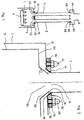
- Fig. 1 shows a hot air heat exchanger, of a heat exchanger housing only the bottom 10, which is formed by the ceiling of an outer chamber 1, and the ceiling 60 with the subsequent exhaust pipe 6 are shown.
- Two curved heat exchanger tubes 2, 3 are guided through the heat exchanger housing around a blower (not shown here).
- a gas burner 4 with a plurality of combustion nozzles pointing vertically upward is provided in the base region of a prechamber 5, which is arranged in the outer chamber 1 at a distance on all sides.
- the prechamber 5 is therefore almost completely surrounded by relatively cool air, which can freely flow into the space between the prechamber 5 and the outer chamber 1.
- openings 12, 14 are formed in the ceiling 10 of the outer chamber 1, which taper spherically in the vertical direction, but with a smaller slope than the exhaust openings 52, 54.
- the venturi principle can also be used then if the slopes are identical or substantially the same.
- the heat exchanger tubes 2, 3 are placed on the openings 12, 14 and connected to the ceiling 10 of the outer chamber 1 by a flange connection, as is more clearly described in connection with FIG.
- An opening 62, 64 is also provided in the ceiling 60 of the heat exchanger housing for each heat exchanger tube 2, 3, the connection point being essentially gas-tight by graphite seals 66, 68.
- each heat exchanger tube 2, 3 to be axially slidable in its opening 62, 64. With a suitable diameter, angular mobility is also given.
- the cooled exhaust gases are finally discharged through an exhaust pipe 6.
- Figure 2 shows the area of a connection point between the outer chamber or prechamber and heat exchanger tube in detail.
- an exhaust gas opening 54 is formed, the wall surrounding it tapers conically in the vertical direction.
- the pitch angle ⁇ can be, for example, 45 °.
- An outer chamber 1 is arranged at a distance around the antechamber 5.
- an opening 14 is provided, the wall 16 surrounding it tapers in the vertical direction in the shape of a concave spherical surface.
- the opening 14 is surrounded by an annular bead 18.
- the walls 56, 16 of the two openings namely the exhaust gas opening 54 and the opening 14 in the outer chamber 1, form a constriction in the region of these openings, which acts as a venturi-like nozzle.
- the hot exhaust gas from the burner exiting through the exhaust opening 54 entrains the relatively cool air from the space between the outer chamber 1 and the pre-chamber 5, which has a high speed due to the narrowing in the opening area.
- a comparatively large additional amount of air is thus fed into the heat exchanger tube 3 and causes a high degree of filling there, which is important for good heat transfer.
- the heat exchanger tube 3 itself is conical in its lower end section 32, the slope being chosen so that a circular contact surface and thus a seal against the peripheral wall 16 results.
- a flange 34 which surrounds it and which extends radially outwards.
- the heat exchanger tube 3 is fastened to the ceiling 10 of the outer chamber 1 with a sufficient number of bolts 40, 42, together with nuts, of which only two are shown here, which are guided through bores 36, 38 of the flange 34.
Landscapes
- Engineering & Computer Science (AREA)
- General Engineering & Computer Science (AREA)
- Chemical & Material Sciences (AREA)
- Thermal Sciences (AREA)
- Combustion & Propulsion (AREA)
- Mechanical Engineering (AREA)
- Physics & Mathematics (AREA)
- Heat-Exchange Devices With Radiators And Conduit Assemblies (AREA)
- Fuel Cell (AREA)
- Air-Conditioning For Vehicles (AREA)
- Separation By Low-Temperature Treatments (AREA)
- Gas Burners (AREA)
- Air Supply (AREA)
Applications Claiming Priority (2)
| Application Number | Priority Date | Filing Date | Title |
|---|---|---|---|
| DE4120250 | 1991-06-19 | ||
| DE4120250A DE4120250C1 (enExample) | 1991-06-19 | 1991-06-19 |
Publications (2)
| Publication Number | Publication Date |
|---|---|
| EP0519303A1 EP0519303A1 (de) | 1992-12-23 |
| EP0519303B1 true EP0519303B1 (de) | 1994-08-24 |
Family
ID=6434298
Family Applications (1)
| Application Number | Title | Priority Date | Filing Date |
|---|---|---|---|
| EP92109680A Expired - Lifetime EP0519303B1 (de) | 1991-06-19 | 1992-06-09 | Heissluftwärmetauscher |
Country Status (7)
| Country | Link |
|---|---|
| US (1) | US5199416A (enExample) |
| EP (1) | EP0519303B1 (enExample) |
| JP (1) | JPH04371755A (enExample) |
| AT (1) | ATE110461T1 (enExample) |
| DE (2) | DE4120250C1 (enExample) |
| DK (1) | DK0519303T3 (enExample) |
| ES (1) | ES2061298T3 (enExample) |
Families Citing this family (3)
| Publication number | Priority date | Publication date | Assignee | Title |
|---|---|---|---|---|
| DE9416204U1 (de) | 1994-10-07 | 1994-12-01 | Angelo Po Grandi Cucine S.p.A., Carpi, Modena | Gaswärmeaustauscher |
| US6188045B1 (en) | 2000-04-03 | 2001-02-13 | Alto-Shaam, Inc. | Combination oven with three-stage water atomizer |
| ATE503157T1 (de) * | 2002-07-10 | 2011-04-15 | Winterwarm B V | Brenner- und wärmetauscheranordnung, und lufterhitzer |
Family Cites Families (9)
| Publication number | Priority date | Publication date | Assignee | Title |
|---|---|---|---|---|
| GB769654A (en) * | 1955-05-21 | 1957-03-13 | Albert Lee Nathan | Improvements in or relating to air-heating apparatus |
| FR1395978A (fr) * | 1964-04-11 | 1965-04-16 | Générateur mobile pouvant être utilisé comme appareil de chauffage par air chaud pulsé dans étuve, séchoir à tabac, séchoir à céréales, chauffage des appartements | |
| DE1937034U (de) * | 1965-09-22 | 1966-04-21 | Kurt Zenkner Grunwettersbach U | Wandlufterhitzer. |
| US3820526A (en) * | 1972-05-23 | 1974-06-28 | Werktuigenfab Mulder Nv | Air heater especially for connection to a central heating system |
| US4010728A (en) * | 1975-06-02 | 1977-03-08 | American Standard, Inc. | Circulating fireplace system |
| US4325353A (en) * | 1980-05-02 | 1982-04-20 | Husa Marlin V | Heating apparatus |
| US4469276A (en) * | 1982-09-30 | 1984-09-04 | Al Marcum | Heat recovery apparatus |
| US5061463A (en) * | 1989-08-24 | 1991-10-29 | Hoechst Celanese Corporation | Coincinerator apparatus and method for processing waste gases |
| US5016613A (en) * | 1990-07-12 | 1991-05-21 | Majco Building Specialties, L.P. | Fireplace top wall assembly and cooling system |
-
1991
- 1991-06-19 DE DE4120250A patent/DE4120250C1/de not_active Expired - Fee Related
- 1991-12-17 US US07/808,743 patent/US5199416A/en not_active Expired - Lifetime
- 1991-12-19 JP JP3354651A patent/JPH04371755A/ja active Pending
-
1992
- 1992-06-09 AT AT92109680T patent/ATE110461T1/de not_active IP Right Cessation
- 1992-06-09 DE DE59200400T patent/DE59200400D1/de not_active Expired - Lifetime
- 1992-06-09 ES ES92109680T patent/ES2061298T3/es not_active Expired - Lifetime
- 1992-06-09 EP EP92109680A patent/EP0519303B1/de not_active Expired - Lifetime
- 1992-06-09 DK DK92109680.6T patent/DK0519303T3/da active
Also Published As
| Publication number | Publication date |
|---|---|
| US5199416A (en) | 1993-04-06 |
| DE4120250C1 (enExample) | 1992-12-24 |
| EP0519303A1 (de) | 1992-12-23 |
| DK0519303T3 (da) | 1995-01-09 |
| DE59200400D1 (de) | 1994-09-29 |
| JPH04371755A (ja) | 1992-12-24 |
| ES2061298T3 (es) | 1994-12-01 |
| ATE110461T1 (de) | 1994-09-15 |
Similar Documents
| Publication | Publication Date | Title |
|---|---|---|
| EP0164576B1 (de) | Industriebrenner für gasförmige oder flüssige Brennstoffe | |
| EP1214514B1 (de) | Fluideinleitung für ein heisses fluid in einer hohlraumstruktur | |
| DE2438845C3 (de) | Ringbrennkammer für ein Gasturbinentriebwerk | |
| EP0544853B1 (de) | Luftheizgerät | |
| DE4326802A1 (de) | Brennstofflanze für flüssige und/oder gasförmige Brennstoffe sowie Verfahren zu deren Betrieb | |
| DE2406277A1 (de) | Einrichtung zur kuehlfilmbildung fuer brennkammern | |
| EP0029939B1 (de) | Industriebrenner | |
| CH301138A (de) | Verbrennungseinrichtung mit Zyklonbrennkammer. | |
| DE2836433A1 (de) | Rekuperatorbrenner fuer industrieoefen | |
| DE2808051A1 (de) | Brennkammer fuer eine gasturbine o.dgl. | |
| DE2916324C2 (enExample) | ||
| EP0519303B1 (de) | Heissluftwärmetauscher | |
| EP0128463B1 (de) | Raumheizgerät für Kleinräume | |
| DE3034193A1 (de) | Mantelstrahlheizrohr | |
| EP1286115A1 (de) | Thermische Nachverbrennungsanlage | |
| EP0229231B1 (de) | Brenner zum Verbrennen von Brennstoffen unter verminderter Bildung von Stickoxiden | |
| DE2339366A1 (de) | Brennkammer fuer gasturbine | |
| DE3438320C2 (enExample) | ||
| EP0292580B1 (de) | Heizkessel | |
| DE2432330C2 (de) | Brenner mit hoher Austrittsgeschwindigkeit der Rauchgase | |
| DE2521086A1 (de) | Winderhitzer | |
| DE2012948A1 (de) | Verbindung von Mantelsegmenten in einer Brennkammer sowie Herstellungsverfahren der Verbindung | |
| DE2943289A1 (de) | Brenner fuer fluessige und/oder gasfoermige brennstoffe, insbesondere fuer industrielle oefen | |
| DE2162139A1 (de) | Waermetauscher | |
| DE1048442B (enExample) |
Legal Events
| Date | Code | Title | Description |
|---|---|---|---|
| PUAI | Public reference made under article 153(3) epc to a published international application that has entered the european phase |
Free format text: ORIGINAL CODE: 0009012 |
|
| AK | Designated contracting states |
Kind code of ref document: A1 Designated state(s): AT BE CH DE DK ES FR GB GR IT LI LU NL PT SE |
|
| 17P | Request for examination filed |
Effective date: 19930525 |
|
| 17Q | First examination report despatched |
Effective date: 19931112 |
|
| GRAA | (expected) grant |
Free format text: ORIGINAL CODE: 0009210 |
|
| AK | Designated contracting states |
Kind code of ref document: B1 Designated state(s): AT BE CH DE DK ES FR GB GR IT LI LU NL PT SE |
|
| REF | Corresponds to: |
Ref document number: 110461 Country of ref document: AT Date of ref document: 19940915 Kind code of ref document: T |
|
| ET | Fr: translation filed | ||
| GBT | Gb: translation of ep patent filed (gb section 77(6)(a)/1977) |
Effective date: 19940826 |
|
| REF | Corresponds to: |
Ref document number: 59200400 Country of ref document: DE Date of ref document: 19940929 |
|
| ITF | It: translation for a ep patent filed | ||
| REG | Reference to a national code |
Ref country code: GR Ref legal event code: FG4A Free format text: 3013223 |
|
| REG | Reference to a national code |
Ref country code: ES Ref legal event code: FG2A Ref document number: 2061298 Country of ref document: ES Kind code of ref document: T3 |
|
| REG | Reference to a national code |
Ref country code: DK Ref legal event code: T3 |
|
| EAL | Se: european patent in force in sweden |
Ref document number: 92109680.6 |
|
| SC4A | Pt: translation is available |
Free format text: 940829 AVAILABILITY OF NATIONAL TRANSLATION |
|
| PLBE | No opposition filed within time limit |
Free format text: ORIGINAL CODE: 0009261 |
|
| STAA | Information on the status of an ep patent application or granted ep patent |
Free format text: STATUS: NO OPPOSITION FILED WITHIN TIME LIMIT |
|
| 26N | No opposition filed | ||
| PGFP | Annual fee paid to national office [announced via postgrant information from national office to epo] |
Ref country code: PT Payment date: 20010522 Year of fee payment: 10 |
|
| PGFP | Annual fee paid to national office [announced via postgrant information from national office to epo] |
Ref country code: LU Payment date: 20010611 Year of fee payment: 10 |
|
| PGFP | Annual fee paid to national office [announced via postgrant information from national office to epo] |
Ref country code: DK Payment date: 20010613 Year of fee payment: 10 Ref country code: AT Payment date: 20010613 Year of fee payment: 10 |
|
| PGFP | Annual fee paid to national office [announced via postgrant information from national office to epo] |
Ref country code: CH Payment date: 20010615 Year of fee payment: 10 |
|
| PGFP | Annual fee paid to national office [announced via postgrant information from national office to epo] |
Ref country code: GR Payment date: 20010627 Year of fee payment: 10 |
|
| PGFP | Annual fee paid to national office [announced via postgrant information from national office to epo] |
Ref country code: ES Payment date: 20010629 Year of fee payment: 10 |
|
| PGFP | Annual fee paid to national office [announced via postgrant information from national office to epo] |
Ref country code: BE Payment date: 20010816 Year of fee payment: 10 |
|
| REG | Reference to a national code |
Ref country code: GB Ref legal event code: IF02 |
|
| PG25 | Lapsed in a contracting state [announced via postgrant information from national office to epo] |
Ref country code: LU Free format text: LAPSE BECAUSE OF NON-PAYMENT OF DUE FEES Effective date: 20020609 Ref country code: AT Free format text: LAPSE BECAUSE OF NON-PAYMENT OF DUE FEES Effective date: 20020609 |
|
| PG25 | Lapsed in a contracting state [announced via postgrant information from national office to epo] |
Ref country code: ES Free format text: LAPSE BECAUSE OF NON-PAYMENT OF DUE FEES Effective date: 20020610 |
|
| PGFP | Annual fee paid to national office [announced via postgrant information from national office to epo] |
Ref country code: SE Payment date: 20020611 Year of fee payment: 11 |
|
| PGFP | Annual fee paid to national office [announced via postgrant information from national office to epo] |
Ref country code: NL Payment date: 20020628 Year of fee payment: 11 |
|
| PG25 | Lapsed in a contracting state [announced via postgrant information from national office to epo] |
Ref country code: CH Free format text: LAPSE BECAUSE OF NON-PAYMENT OF DUE FEES Effective date: 20020630 Ref country code: LI Free format text: LAPSE BECAUSE OF NON-PAYMENT OF DUE FEES Effective date: 20020630 Ref country code: BE Free format text: LAPSE BECAUSE OF NON-PAYMENT OF DUE FEES Effective date: 20020630 |
|
| PG25 | Lapsed in a contracting state [announced via postgrant information from national office to epo] |
Ref country code: DK Free format text: LAPSE BECAUSE OF NON-PAYMENT OF DUE FEES Effective date: 20020731 |
|
| BERE | Be: lapsed |
Owner name: *RATIONAL G.M.B.H. Effective date: 20020630 |
|
| PG25 | Lapsed in a contracting state [announced via postgrant information from national office to epo] |
Ref country code: PT Free format text: LAPSE BECAUSE OF NON-PAYMENT OF DUE FEES Effective date: 20021231 Ref country code: GR Free format text: LAPSE BECAUSE OF NON-PAYMENT OF DUE FEES Effective date: 20021231 |
|
| REG | Reference to a national code |
Ref country code: DK Ref legal event code: EBP |
|
| REG | Reference to a national code |
Ref country code: CH Ref legal event code: PL |
|
| REG | Reference to a national code |
Ref country code: PT Ref legal event code: MM4A Free format text: LAPSE DUE TO NON-PAYMENT OF FEES Effective date: 20021231 |
|
| PGFP | Annual fee paid to national office [announced via postgrant information from national office to epo] |
Ref country code: GB Payment date: 20030604 Year of fee payment: 12 |
|
| PG25 | Lapsed in a contracting state [announced via postgrant information from national office to epo] |
Ref country code: SE Free format text: LAPSE BECAUSE OF NON-PAYMENT OF DUE FEES Effective date: 20030610 |
|
| PG25 | Lapsed in a contracting state [announced via postgrant information from national office to epo] |
Ref country code: NL Free format text: LAPSE BECAUSE OF NON-PAYMENT OF DUE FEES Effective date: 20040101 |
|
| EUG | Se: european patent has lapsed | ||
| NLV4 | Nl: lapsed or anulled due to non-payment of the annual fee |
Effective date: 20040101 |
|
| REG | Reference to a national code |
Ref country code: ES Ref legal event code: FD2A Effective date: 20030711 |
|
| PG25 | Lapsed in a contracting state [announced via postgrant information from national office to epo] |
Ref country code: GB Free format text: LAPSE BECAUSE OF NON-PAYMENT OF DUE FEES Effective date: 20040609 |
|
| GBPC | Gb: european patent ceased through non-payment of renewal fee |
Effective date: 20040609 |
|
| PGFP | Annual fee paid to national office [announced via postgrant information from national office to epo] |
Ref country code: FR Payment date: 20080617 Year of fee payment: 17 |
|
| REG | Reference to a national code |
Ref country code: FR Ref legal event code: ST Effective date: 20100226 |
|
| PG25 | Lapsed in a contracting state [announced via postgrant information from national office to epo] |
Ref country code: FR Free format text: LAPSE BECAUSE OF NON-PAYMENT OF DUE FEES Effective date: 20090630 |
|
| PGFP | Annual fee paid to national office [announced via postgrant information from national office to epo] |
Ref country code: DE Payment date: 20110826 Year of fee payment: 20 |
|
| PGFP | Annual fee paid to national office [announced via postgrant information from national office to epo] |
Ref country code: IT Payment date: 20110627 Year of fee payment: 20 |
|
| REG | Reference to a national code |
Ref country code: DE Ref legal event code: R071 Ref document number: 59200400 Country of ref document: DE |
|
| REG | Reference to a national code |
Ref country code: DE Ref legal event code: R071 Ref document number: 59200400 Country of ref document: DE |
|
| PG25 | Lapsed in a contracting state [announced via postgrant information from national office to epo] |
Ref country code: DE Free format text: LAPSE BECAUSE OF EXPIRATION OF PROTECTION Effective date: 20120612 |