EP0519255A2 - Système d'inspection pour les défauts et procédé d'inspection - Google Patents
Système d'inspection pour les défauts et procédé d'inspection Download PDFInfo
- Publication number
- EP0519255A2 EP0519255A2 EP92109219A EP92109219A EP0519255A2 EP 0519255 A2 EP0519255 A2 EP 0519255A2 EP 92109219 A EP92109219 A EP 92109219A EP 92109219 A EP92109219 A EP 92109219A EP 0519255 A2 EP0519255 A2 EP 0519255A2
- Authority
- EP
- European Patent Office
- Prior art keywords
- peaks
- density
- differences
- picture elements
- along
- Prior art date
- Legal status (The legal status is an assumption and is not a legal conclusion. Google has not performed a legal analysis and makes no representation as to the accuracy of the status listed.)
- Withdrawn
Links
Images


Classifications
-
- G—PHYSICS
- G01—MEASURING; TESTING
- G01N—INVESTIGATING OR ANALYSING MATERIALS BY DETERMINING THEIR CHEMICAL OR PHYSICAL PROPERTIES
- G01N21/00—Investigating or analysing materials by the use of optical means, i.e. using sub-millimetre waves, infrared, visible or ultraviolet light
- G01N21/84—Systems specially adapted for particular applications
- G01N21/88—Investigating the presence of flaws or contamination
- G01N21/89—Investigating the presence of flaws or contamination in moving material, e.g. running paper or textiles
-
- G—PHYSICS
- G01—MEASURING; TESTING
- G01N—INVESTIGATING OR ANALYSING MATERIALS BY DETERMINING THEIR CHEMICAL OR PHYSICAL PROPERTIES
- G01N21/00—Investigating or analysing materials by the use of optical means, i.e. using sub-millimetre waves, infrared, visible or ultraviolet light
- G01N21/84—Systems specially adapted for particular applications
- G01N21/88—Investigating the presence of flaws or contamination
- G01N21/8851—Scan or image signal processing specially adapted therefor, e.g. for scan signal adjustment, for detecting different kinds of defects, for compensating for structures, markings, edges
- G01N2021/8896—Circuits specially adapted for system specific signal conditioning
-
- G—PHYSICS
- G01—MEASURING; TESTING
- G01N—INVESTIGATING OR ANALYSING MATERIALS BY DETERMINING THEIR CHEMICAL OR PHYSICAL PROPERTIES
- G01N21/00—Investigating or analysing materials by the use of optical means, i.e. using sub-millimetre waves, infrared, visible or ultraviolet light
- G01N21/84—Systems specially adapted for particular applications
- G01N21/88—Investigating the presence of flaws or contamination
- G01N21/89—Investigating the presence of flaws or contamination in moving material, e.g. running paper or textiles
- G01N21/8901—Optical details; Scanning details
- G01N2021/8905—Directional selective optics, e.g. slits, spatial filters
Definitions
- the present invention relates to a defect inspection system for scanning a test piece to be inspected to pick up image signals which are processed to detect any faults or defects on the surface of the inspected material.
- the surface to be inspected is optically scanned to detect faults on the surface of the test piece or internal defects of the test piece.
- image signals obtained by scanning the test piece are compared with a pre-set threshold to discriminate that a defect is present when a particular image signal is above or below the threshold.
- the image signals have output levels which are fluctuated extensively.
- the output levels of the read image signals are extensively fluctuated due to inuniformality of the characteristics of each picture element or the unevenness of the intensity of illumination.
- the output levels of the signals are also greatly affected by the change in incidence angle of the scanning beam with the surface of the test piece and also by the change in incidence angle of the reflected beam into the optical system.
- the output levels of the image signals are fluctuated due to topographical feature of the scanned surface, which is brought during the fabrication of the test piece and should not be judged as a defect, an example of such topographical feature being trivial undulation or other inserious unevenness on the surface of a rolled steel plate.
- An object of this invention is to provide a defect inspection system wherein the image signals are subjected to spatial-filtering while using a differentiation filter which is defined or selected to have an optimum differentiation direction to facilitate reliable defect detection operation at a high sensitivity.
- Another object of this invention is to provide a defect inspection system wherein a differentiation filter having an optimum differentiation direction suited for the inspection of the test piece having a particular topographical feature is automatically selected and used in the spatial-filtering to realize reliable defect detection operation at a high sensitivity.
- a further object of this invention is to provide a process for detecting any defects at high sensitivity by selectively using a differentiation filter having an optimum differentiation direction suited for the inspection of the test piece having a particular topographical feature.
- the object of this invention is attained by the provision of a defect inspection system for scanning a surface of a test piece to pick up image signals from which any defects are detected, which comprises:
- the differentiation filter used for spatial-filtering may be defined or selected manually while referring to the output from the background noise discriminator. However, it is desirous that the differentiation filter is defined or selected automatically. For example, plural differentiation filters having different differentiation directions may be stored in a memory so that an optimum differentiation filter is automatically selected depending on the result of discriminating the topographical feature.
- the topographical feature of the inspected surface may be discriminated, for example; by comparing the differences in density of adjacent picture elements along the main scanning direction with the differences in density of adjacent picture elements along the subsidiary direction; by comparing the differences in density of the picture elements spaced from one another at a pre-set number of picture elements along the main scaning direction with the differences in density of the picture elements spaced from one another at a pre-set numeber of picture elements along the subsidiary scanning direction; or by comparing the sum of the differences in density along the main scanning direction between each picture element and the average density of all picture elements with the sum of the differences in density along the subsidiary scanning direction between each picture element and the average density of all picture elements.
- the sum of differences may be calculated by totalizing the absolute values of respective differences or the sum of sqaure numbers of respective differences may be totalized.
- the image density signals are initially converted into digital signals and then differentiated through a differentiation filter, low frequency components which cause an extensive fluctuation in output level are removed. As a result, the output level of the signals picked up by scanning the normal background area, which might contain some topographical feature, is maintained at a substantially constant level. Any defects can be detected at a high sensitivity by comparing the differentiated signals with a pre-set threshold.
- the sensitivity in inspection of defects is improved by the use of the optimum differentiation filter.
- the object of this invention is attained by the provision of a defect inspection system for scanning a surface of a test piece to pick up image signals from which any defects are detected, which comprises:
- the histogram used for the discrimination of the topographical feature may be a histogram of the differences in density along the main and subsidiary directions between adjacent picture elements or between a certain picture element and a picture element spaced by a pre-set number of picture elements from said ceratin picture element, or a histogram of the differences in density between each picture element and the average density of all picture elements.
- abosolute values of differences or sqaure numbers of differences may be used.
- the sensitivity in inspection of defects is improved by the use of the optimum differentiation filter.
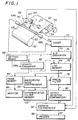
- reference numeral 50 designates a test piece, such as steel plate, paper sheet or plastics film, to be inspected.
- the test piece 50 is supplied from a supply roller 52 and taken up by a take-up roller 54.
- the take-up roller 54 is driven by a take-up motor 56.
- the surface of the test piece 50 is scanned by a flying spot type image detector 58 to pick up image signals.
- the image detector 58 has a laser beam source 60 for generating a scanning laser beam L which is reflected by a rotary mirror (polygonal mirror) 64 to scan the test piece 50 at a constant angular rate along a main scanning direction, i.e. along the widthwise direction.
- the beam reflected by the surface of the test piece 50 is received by a light receiving rod 66 and then guided to a pair of light receivers 68 (68a, 68b).
- the light receiving rod 66 is disposed vicinal to and parallel to a main scanning line 70 for the scanning beam L so that the beam reflected by the surface of the test piece 50 and received by the rod 66 is totally reflected by the internal surface of the rod 66 to be guided to the ends of the rod 66.
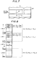
- Photo-multipliers or like light receivers 68 are attached to the ends of the rod 66 to detect the light quantities of the recived beam. Image signals put out from each light receiver 68 are amplified by a pre-amplifier and a main amplifier (not shown), and then the wave forms thereof are regulated or shapened to be analog image signals a1 and a2 shown in Fig. 2.
- Each of the signal a1 and a2 includes a series of signals obtained by scanning along the main scanning line 70 appearing at a constant time interval.
- Signals d11, d12, d21 and d22 in Fig. 2 correspond to defects on the surface of the test piece 50.
- the levels of respective signals a1 and a2 are lowered as the scanning beam L is remoter from the main scanning line 70, and take higher values as the beam L reaches close to the main scanning line 70.
- both signals a1 and a2 are added together by an adder 72 to exclude the influence by the change in scanned position on the main scanning line 70.
- the added signal a3 is converted into a degital density signal a4 by an A/D converter 74, for example, having 256 tone graduations, and stored in a line memory 76.
- the line memory 76 has a memory capacity at least equivalent to the product (N x M) obtained by multiplying the number N of picture elements contained in one main scanning line by the number M, which is a larger number than the number of lines contained in the used spatial filter which will be described hereinafter.
- the line memory 76 stores these digital signals a4 for every scanning operations, the storing of the signals being effected in synchronism with feeding of the inspection width gate signals.
- the line memory 76 has a ring buffer structure so that a new datum is written on the earliest datum as all of the memory areas in the line memory 76 have been filled.
- the inspection width gate signal indicates the width of inspected area by every scanning along the main scanning line, the inspection width gate signal being fed in synchronism with the rotation of the rotary mirror 64.
- the line memory 76 may be replaced by a delay circuit for delaying the signals a3 by n lines, delaying being carried out serially one line for every scanning operation along the main scanning line.
- the signal a5 from the line memory 76 is subjected to spatial-filtering by a differentiation filter in the spatial filtering means 78.
- this differentiation processing is effected by covering a spatial filter F on (3 x 3) picture elements including a center picture element now on inspection to obtain the integration product of signals from these (3 x 3) picture elements so that the total sum in taken as the output. Similar operations are repeated from the top left picture element to the right bottom picture element following to the order of raster scanning.
- One or more filters each having a overlapping factors as shown in Fig. 5 may be selectively used as the spatial filter used for the spatial-filtering operation.
- This filter comprises paired two filters, i.e. a filter ⁇ x f for differentiating along the line direction and another filter ⁇ y f for differentiating along the row direction; and the sum of the absolute values of the outputs from both filters, the output from either one of these filter having a larger value, the output from either one of these filters or absolute value of the output from either one of these filters is used as the final output.
- an optimum differentiation filter suited for the discrimination of the topographical feature by a background noise discriminator 100, which will be described hereinafter, is selectively used.
- the contour of each image along both of X and Y directions is claified to improve the defect detection sensitivity carried out by the subsequent operations.
- a density converter 82 may be incorporated to convert the density of the signal x , which has been already subjected to A/D conversion, while using a predetermined density conversion table, and the signal x processed through the density conversion processing is fed through the line memory 76 to the spatial filter 78 to be subjected to spatial-filtering.
- the signal a4 obtained through A/D conversion is fed to the density converter 82 where it is subjected to density conversion.
- the output signal X from the density converter 82 is once passed to a frame memory 84 to be stored and then displayed as a converted image on the television monitor 86.
- the density tone conversion is effected, for example, by using a table having the characteristics shown in Fig. 6.
- the abscissa denotes the density of the input density signal x
- the ordinate denotes the output signal X after subjected to density conversion.
- Each of these density signals x and X has, for example, 256 tone graduations.
- the densities within a range extending to cover a pre-set width 2 a , the center line of said pre-set width 2 a corresponding to the background density lebel c are converted into a certain constant density (e.g. the 127th graduation), and the densities out of said range are converted into either one of the maximum value (255the graduation) or the minimum graduation (0th graduation) by the use of a conversion factor (slope) b .
- the pre-set values a , b and c are shiftable by means of a manually operable setting means 88.
- the operator of the system operates the setting means 88 while monitoring the image displayed on the television monitor 86 so that the noises contained in the background field are eliminated.
- the signal y obtained by subjecting to spatial-filtering through a spatial filter 78 is deprived of low frequency components contained in the signal X or a4, whereby the defective portion is made distinctive.
- a defect discriminator 90 is provided to compare this signal y with thresholds v 1 and v 2 and the portion or surface area of the inspected material is discriminated as defective when y > v 1 or y ⁇ v 2 (see Fig. 6).
- any defect may also be discriminated by setting a threshold relating to the number of picture elements within a certain constant mask size (mask size defining the number of thresholds). For instance, a certain inspected picture element is sorted as having a value of 1 when the number of picture elements each having a density more than the threshold v 1 or a density less than the threshold v 2 is more than a pre-set number (for example 4), whereas the inspected picture element is sorted as a value of 0 when the number of picture elements each having a density more than the threshold v 1 or a density less than the threshold v 2 is not more than the same pre-set number.
- a pre-set number for example 4
- the mask size of the spatial filter used in this step is not limited to the 3 x 3 size as used in the illustrated embodiment.
- a mask having 4 x 4, 5 x 5 size may be used depending on the pattern of the topographical feature.
- This signal z indicating any defect is fed to an address discriminator 92 to determine the address Ad of the defect.
- This address Ad may be determined by the combination of the output from a feed rate sensor (pulse generator) 57 and a rotating angle of a motor 62. However, since there is some time delay required for the processing of the signals, such a time delay must be taken into account when the address Ad is determined.
- the ordinates of respective signals are stored together with the signals a4 and X in the line memory 76 and the frame memory 84, so that the ordinates of each defect can be read from these memories 76 and 84.
- the results are recorded in a recorder, such as a printer 94.
- a background noise discriminator 100 for selecting the optimum differentiation filter used in the spatial filter 78 will now be described with reference to Figs. 7, 8 and 9. Discrimination of the topographical feature of the inspected surface by this background noise discriminator 100 is effected by scanning a pre-selected area A containing (n x m) picture elements and located at the substantial center of the fore end of the test piece 50, as shown in Fig. 7.
- the number n of the picture elements along the main scanning direction (X direction) is set to, for example, 256
- the number m of the picture elements (i.e. the scanned row number) along the subsidiary scanning direction (Y direction) is set to, for example, 32.
- the line number M which can be stored in the line memory 76 is larger than or equal to the line number m .
- the density of the picture element (p, q) within this area A is indicated by F p,q .
- the density F(m, n) of a specific picture element within the area A is read from the line memory 76, and the differences in density, namely the differences in density of the specific picture element and the adjacent picture elements aligned along the main and subsidiary scanning directions, are determined.
- the arithmetic operation for the determination of difference in density along the main scanning direction is shown in Fig. 8.
- ⁇ j F 0,j-1 - F 0,j
- the absolute values of these differences are totalized along the line 0 to obtain the sum X0 as follows.
- wherein ⁇ j is the sum of the differences where j 1 to 255.
- the average X of the differences may be obtained as follows (Step 102).
- X (1/p x ) ⁇ i X i
- the averge Y of the differences along the subsidiary scanning direction may be obtained from the following equation (Step 102).
- P y (L y -1)L x
- the topographical feature of the inspected surface such as the directivity of the topographical feature, can be discriminated by comparing the thus obtained values X and Y.
- the difference along the Y direction (row direction) is larger so that it is discriminated that the topographical feature of the inspected surface is characterized by the change in texture or formation extending along the X direction (line direction).
- the value (Y - X) is smaller than the pre-set threshold TH(Y)
- the difference along the X direction (line direction) is larger so that it is discriminated that the topographical feature of the inspected surface is characterized by the change in texture or formation extending along the Y direction (row direction) (Steps 108 and 110).
- the differentiation filter ⁇ x f is selectively used when the topographical feature of the inspected surface is characterized by the change in texture or formation extending along the X direction (line direction), whereas the differentiation filter ⁇ y f is selectively used when the topographical feature of the inspected surface is characterized by the change in texture or formation extending along the Y direction (row direction). (Steps 112 and 114).
- the topographical feature is characterized by changes in texture extending along both of the X and Y directions at a substantially equal extent (Step 116).
- the signal a5 is differentiated two-dimensionally. In other words, the sum of the both differentiation filters ⁇ x f and ⁇ y f is used (Step 118).
- the present invention is not limited only to the aforementioned embodiment.
- the absolute values of differences each obtained by comparing a difference between a certain picture element and a picture element spaced by one or more picture element from said certain picture elements may be totalized along the X and Y directions to determine the sums X and Y.
- the topographical feature of the inspected surface is enhanced or emphasized by increasing the sums of the absolute values X and Y when the densities of the picture elements are gently changed.
- the values of the sums X and Y obtained by totalizing the differences between respective picture elements or the differences between the densities of respective picture elements and the average density are the parameters indicating the clearness and significance of the topographical feature. Accordingly, an optimum differentiation filter having a variable mask size may be selected in consideration of these parameters. For instance, when the sums X and Y are small, it is judged that the topographical feature is vague or unclear or the pattern of the topographical feature is large. Under such circumstances, the thresholds v 1 and v 2 used in the background noise discriminator 90 are decreased, or the mask size (which defines the number of thresholds) of spatial filter is expanded to 5 x 5 or 7 x 7, or the picture element number threshold is increased or decreased.
- the optimum differentiation filter used in discrimintion of the particular topographical feature is selected from the differentiation filter memory 102 so that the subsequent defect discrimination operation (Step 120 in Fig. 9) is effected while using the thus selected differentiation filter in the spatial filter 78.
- the defects can be detected at a high sensitivity.
- the optimum differentiation filter may be selected automatically from plural differentiation filters having different directions of differentiation, while discriminating the directivity of the topographical feature.
- the absolute values of the differences between the densities of respectsive picture elements and the average density or the square numbers of differences may be totalized.
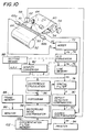
- Fig. 10 is a block diagram showin a second embodiment of the invention
- Fig. 11 is a block diagram showing the operation sequence processed through the second embodiment
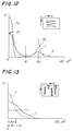
- Figs. 12 and 13 are graphs each showing histogram patterns used for the discrimination of topograpical feature.
- This second embodiment is the same as the first embodiment except that the operation sequence (Fig. 11) for selecting the optimum differentiation filter used in the spatial-filter 78 is different from the operation sequence processed through the first embodiment. Accordingly, the same parts are designated by the same reference numerals and the description thereof and the operation steps similar to those in the first embodiment will not be repeated.
- the topographical feature of the inspected surface is discriminated by scanning a predetermined area A containing (n x m) picture elements located at the substantial center of the fore end region of the test piece 50.
- the number n of the picture elements along the main scanning direction (X direction) is set to, for example, 256
- the number m of the picture elements ( i.e. the scanned row number) along the subsidiary scanning direction (Y direction) is set to, for example, 32.
- the line number M which can be stored in the line memory 76 is larger than or equal to the line number m .
- the density of the picture element (p, q) within this area A is indicated by F p,q .
- the density F(m, n) of a specific picture element within the area A is read from the line memory 76, and the absolute values of differences in density, namely the absolute values of differences in density
- the arithmetic operation for the determination of difference in density along the main scanning direction is shown in Fig. 8.
- (F 0,j-1 - F o,j
- a histograms X (Figs. 12 and 13) are drawn by a histogram means 98 while plotting these p x numbers of the absolute values
- of the diffrences ⁇ i along the subsidiary scanning direction are calculated by the difference calculator 96 (Step 202).
- histograms Y (Figs. 12 and 13) are drwan by the histogram means 98 (Step 204).
- the topographical feature of the inspected surface can be discriminated by comparing these histograms X and Y in the background noise discriminator 100.
- each of the histograms X and Y has a first peak P1 at which the difference ⁇ is 0 and a second peak P2 at a position (
- ⁇ 0) where a significant contrast in the contour of the topographical feature appears.
- the ordinate of the graph of Fig. 12 denotes the frequency of the changes in the topographical feature.
- along the Y direction traverses the contour of the topographical feature at a time smaller than the time along the X direction so that the height of the second peak P2 of the histogram Y is higher than the height of the second peak P2 of the histogam X. Accordingly, by comparing the second peak P2 of the histogram Y with the second peak P2 of the histogram X, the directivity of the topographical feature can be discriminated. Meanwhile, the first peak P0 shown by the real line in Fig. 12 appears when the inspected surface has no significant topographical feature.
- Presence or absence of the second peaks P2 is discriminated by the Steps 206 and 208 in Fig. 11.
- the peaks P2 of the histograms X and Y are compared with each other.
- the peak P2 of the histogram Y is higher than the peak P2 of the histogram X (X ⁇ Y)
- a differentiation filter ⁇ x f for differentiating along the X direction is selected (Step 214).
- Step 216 when the peak P2 of the histogram X is higher than the peak P2 of the histogram Y, it is judged that the directivity of the topographical feature extends along the Y direction (Step 216), and a differentiation filter ⁇ y f for differentiating along the Y direction is selected (Step 218).
- Step 212 When only the histogram Y has the second peak P2 and the histogram X has no second peak (Steps 206 and 220), it is judged that the topographical feature has a directivity along the X direction (Step 212); whereas when only the histogram X has the second peak P2 and the histogram Y has no second peak (Steps 206 and 208), it is judged that the topographical feature has a directivity along the Y direction (Step 216).
- Step 222 When both of the histograms X and Y has only the first peak P1 (Step 222), it is judged that the topographical feature extends two-dimensionally at a substantially equivalent extent along both directions (224). In such a case, a differentiation filter ( ⁇ x f + ⁇ y f) for effecting differentiation along both directions is selected (Step 226).
- a threshold ⁇ is set to have a value intermediate of these peaks P1 and P2 and the threshold value is added to or subtract from the average density to use as the density threshold v1 or v2 in the defect detector 90.
- the widths of the first peaks P1 of the histograms X and Y are broadened.
- the width of the peak P1 of the histogram X is broader than the width of the peak P1 of the histogram Y in the illustrated embodiment.
- the present invention is not limited only to the aforementioned embodiment.
- the absolute values of differences each obtained by comparing a difference between a certain picture element and a picture element spaced by one or more picture element from said certain picture elements may be totalized along the X and Y directions to draw the histograms X and Y.
- the topographical feature of the inspected surface is enhanced or emphasized by increasing the differences and the absolute values of the differences when the densities of the picture elements are gently changed.
- the histograms X and Y may also be drawn by plotting the numbers of the differences in density of adjacent picture elements or the picture elements spaced by predetermined number of picture elements, so that the thus drawn histograms X and Y are compared with each other.
- square numbers of differences in the preparation of the histograms X and Y unclear or little change in topographical feature can be enhanced to facilitate the operation of discriminating the topographical feature.
- the topographical feature of the inspected surface is discriminated while referring to the number of the peaks appearing in the histogram, heights of the second peaks, and the widths of the first peaks.
- the present invention is not limited only to the use of such parameters.
- the topographical feature may be discriminated by using other parameters, such as the positions or areas of the peaks appearing in the histograms.
- an optimum differentiation filter having a variable mask size may be selected in consideration of these parameters. For instance, when the widths of the first peaks P1 of the histograms X and Y are broadened and the second peaks P2 are not clear, it is judged that the topographical feature is vague or unclear or the pattern of the topographical feature is large. Under such circumstances, the thresholds v 1 and v 2 used in the background noise discriminator 90 are decreased, or the mask size of the differentiation filter is expanded to 5 x 5 or 7 x 7, or the picture element number threshold is increased or decreased.
- the optimum differentiation filter used in discrimintion of the particular topographical feature is selected from the differentiation filter memory 102 so that the subsequent defect discrimination operation (Step 228 in Fig. 11) is effected while using the thus selected differentiation filter in the spatial filter 78.
- the defects can be detected at a high sensitivity.
- the optimum filter may be selected manually or automatically from plural differentiation filters having different directions of differentiation, while discriminating the directivity of the topographical feature.
- the absolute values of the differences between the densities of respective picture element may be used to draw the histograms.
- the histograms may be drawn by plotting the differences between the average density of picture elements contained in a proper area and the density of each picture element, or the square numbers of the differences.
- the topographical feature may be discriminated by comparing either one parameters, including the number of peaks, the positions of peaks, the heights of peaks, the areas of peaks and the widths of peaks, appearing in the histograms.
- each of the first and second embodiments has been incorporated with a so-called flying spot type scanning device wherein the surface of the test piece is scanned by a laser beam which is reflected by the scanned surface
- a so-called flying image type device wherein the test piece is scanned by a linear light source extending in the widthwise direction of the test piece and the reflected light is passed through a rotary mirror to a photo-receiver, or a device in which the images are read by a line sensor or an area sensor.
- each of the illustrated embodiments is a system for detecting defective portions appearing on the surface of the test piece
- the present invention is not limited only to the system for the inspection of the surface but includes a system for detecting internal defects.
- a system for detecting internal defects within a steel plate by the utilization of magneto-optical effect may be conceived within the scope of the invention.
- the test piece is magnetized in an AC magnetic field, and the leaked magnetic field from the defective portion is detected by measuring the change in polarization of the reflected light.
Landscapes
- Engineering & Computer Science (AREA)
- Textile Engineering (AREA)
- Physics & Mathematics (AREA)
- Health & Medical Sciences (AREA)
- Life Sciences & Earth Sciences (AREA)
- Chemical & Material Sciences (AREA)
- Analytical Chemistry (AREA)
- Biochemistry (AREA)
- General Health & Medical Sciences (AREA)
- General Physics & Mathematics (AREA)
- Immunology (AREA)
- Pathology (AREA)
- Image Analysis (AREA)
- Investigating Materials By The Use Of Optical Means Adapted For Particular Applications (AREA)
Applications Claiming Priority (4)
| Application Number | Priority Date | Filing Date | Title |
|---|---|---|---|
| JP156030/91 | 1991-05-31 | ||
| JP3156030A JPH04355353A (ja) | 1991-05-31 | 1991-05-31 | 欠陥検査装置 |
| JP3156031A JPH04355354A (ja) | 1991-05-31 | 1991-05-31 | 欠陥検査装置 |
| JP156031/91 | 1991-05-31 |
Publications (2)
| Publication Number | Publication Date |
|---|---|
| EP0519255A2 true EP0519255A2 (fr) | 1992-12-23 |
| EP0519255A3 EP0519255A3 (en) | 1993-07-21 |
Family
ID=26483878
Family Applications (1)
| Application Number | Title | Priority Date | Filing Date |
|---|---|---|---|
| EP19920109219 Withdrawn EP0519255A3 (en) | 1991-05-31 | 1992-06-01 | Defect inspection system and inspection process |
Country Status (1)
| Country | Link |
|---|---|
| EP (1) | EP0519255A3 (fr) |
Cited By (5)
| Publication number | Priority date | Publication date | Assignee | Title |
|---|---|---|---|---|
| EP0563897A1 (fr) * | 1992-03-30 | 1993-10-06 | Fuji Photo Film Co., Ltd. | Système d'inspection de défauts |
| EP1111374A1 (fr) * | 1999-12-23 | 2001-06-27 | Opdix OptoElectronic GmbH, Beratung-Entwicklung-Vertrieb | Détection de non-uniformités de l'épaisseur d'une bande flexible |
| CN113686903A (zh) * | 2021-09-17 | 2021-11-23 | 中国工程物理研究院激光聚变研究中心 | 一种光学元件缺陷检测系统及检测方法 |
| CN114199879A (zh) * | 2021-11-23 | 2022-03-18 | 北京科技大学 | 一种冷轧带钢表面聚集型缺陷的识别方法 |
| CN114581362A (zh) * | 2021-07-22 | 2022-06-03 | 正泰集团研发中心(上海)有限公司 | 光伏组件缺陷检测方法、装置、电子设备和可读存储介质 |
Citations (7)
| Publication number | Priority date | Publication date | Assignee | Title |
|---|---|---|---|---|
| US3790280A (en) * | 1972-05-03 | 1974-02-05 | Western Electric Co | Spatial filtering system utilizing compensating elements |
| US4148061A (en) * | 1972-05-18 | 1979-04-03 | Lemelson Jerome H | Scanning apparatus and method |
| DE3908862A1 (de) * | 1988-03-18 | 1989-09-28 | Fuji Photo Film Co Ltd | Oberflaechenpruefeinrichtung |
| DE3809221A1 (de) * | 1988-03-18 | 1989-09-28 | Roth Electric Gmbh | Verfahren zum detektieren von fehlstellen an pressteilen oder anderen werkstuecken und vorrichtung zur durchfuehrung des verfahrens |
| EP0426182A2 (fr) * | 1989-10-31 | 1991-05-08 | Kla Instruments Corp. | Système et procédé d'inspection optique, automatique et à grande vitesse |
| EP0428751A1 (fr) * | 1989-05-31 | 1991-05-29 | Ishikawajima-Harima Jukogyo Kabushiki Kaisha | Procede de mesure de textures et procede de commande de textures |
| EP0475454A2 (fr) * | 1990-09-14 | 1992-03-18 | Fuji Photo Film Co., Ltd. | Système d'inspection de défauts |
-
1992
- 1992-06-01 EP EP19920109219 patent/EP0519255A3/en not_active Withdrawn
Patent Citations (7)
| Publication number | Priority date | Publication date | Assignee | Title |
|---|---|---|---|---|
| US3790280A (en) * | 1972-05-03 | 1974-02-05 | Western Electric Co | Spatial filtering system utilizing compensating elements |
| US4148061A (en) * | 1972-05-18 | 1979-04-03 | Lemelson Jerome H | Scanning apparatus and method |
| DE3908862A1 (de) * | 1988-03-18 | 1989-09-28 | Fuji Photo Film Co Ltd | Oberflaechenpruefeinrichtung |
| DE3809221A1 (de) * | 1988-03-18 | 1989-09-28 | Roth Electric Gmbh | Verfahren zum detektieren von fehlstellen an pressteilen oder anderen werkstuecken und vorrichtung zur durchfuehrung des verfahrens |
| EP0428751A1 (fr) * | 1989-05-31 | 1991-05-29 | Ishikawajima-Harima Jukogyo Kabushiki Kaisha | Procede de mesure de textures et procede de commande de textures |
| EP0426182A2 (fr) * | 1989-10-31 | 1991-05-08 | Kla Instruments Corp. | Système et procédé d'inspection optique, automatique et à grande vitesse |
| EP0475454A2 (fr) * | 1990-09-14 | 1992-03-18 | Fuji Photo Film Co., Ltd. | Système d'inspection de défauts |
Cited By (7)
| Publication number | Priority date | Publication date | Assignee | Title |
|---|---|---|---|---|
| EP0563897A1 (fr) * | 1992-03-30 | 1993-10-06 | Fuji Photo Film Co., Ltd. | Système d'inspection de défauts |
| EP1111374A1 (fr) * | 1999-12-23 | 2001-06-27 | Opdix OptoElectronic GmbH, Beratung-Entwicklung-Vertrieb | Détection de non-uniformités de l'épaisseur d'une bande flexible |
| WO2001048464A1 (fr) * | 1999-12-23 | 2001-07-05 | Opdix Optoelectronic Gmbh | Detection d'irregularites de l'epaisseur d'une bande de matiere souple |
| CN114581362A (zh) * | 2021-07-22 | 2022-06-03 | 正泰集团研发中心(上海)有限公司 | 光伏组件缺陷检测方法、装置、电子设备和可读存储介质 |
| CN114581362B (zh) * | 2021-07-22 | 2023-11-07 | 正泰集团研发中心(上海)有限公司 | 光伏组件缺陷检测方法、装置、电子设备和可读存储介质 |
| CN113686903A (zh) * | 2021-09-17 | 2021-11-23 | 中国工程物理研究院激光聚变研究中心 | 一种光学元件缺陷检测系统及检测方法 |
| CN114199879A (zh) * | 2021-11-23 | 2022-03-18 | 北京科技大学 | 一种冷轧带钢表面聚集型缺陷的识别方法 |
Also Published As
| Publication number | Publication date |
|---|---|
| EP0519255A3 (en) | 1993-07-21 |
Similar Documents
| Publication | Publication Date | Title |
|---|---|---|
| EP0585759B1 (fr) | Procédé pour détecter et pour faire une image des taches sur la surface d'un élément photographique | |
| US4379632A (en) | Method and apparatus for previewing exposed photographic films or the like | |
| FI96546B (fi) | Menetelmä tasolasin tai tasolasituotteiden optisen laadun määräämistä varten | |
| EP0742431B1 (fr) | Procédé et dispositif de détection de défauts dans des bandes de tissu ou analogue | |
| US4139779A (en) | Method of assessing a printed article | |
| GB1580981A (en) | Method and apparatus for analyzing the shape of the amplitude envelope of a light lobe | |
| EP0744862B1 (fr) | Procédé et appareil pour corriger les signaux de sortie d'une pluralité d'éléments photodétecteurs | |
| US4962539A (en) | Method of recognizing layout and subdivision patterns of radiation images | |
| EP0563897A1 (fr) | Système d'inspection de défauts | |
| EP0519255A2 (fr) | Système d'inspection pour les défauts et procédé d'inspection | |
| US4649422A (en) | Method of and arrangement for determining the sharpness of originals for reproduction | |
| US4995093A (en) | Radiation field recognition method | |
| EP0475454A2 (fr) | Système d'inspection de défauts | |
| JP2691794B2 (ja) | 欠陥検査装置 | |
| JPH08292158A (ja) | 用紙類のしわ検出方法およびしわ検出装置 | |
| GB1580195A (en) | Discrimination circuit arrangements | |
| JP2577655B2 (ja) | 欠陥検査装置 | |
| JPH05280959A (ja) | 欠陥検査装置 | |
| JPH04115147A (ja) | 光学式検査装置 | |
| JP2621690B2 (ja) | 印刷欠陥検査装置 | |
| US5121199A (en) | Color image sensor defect detector using differentiated i and q values | |
| JPS60205683A (ja) | 外観判別方法及びその装置 | |
| JPH04355354A (ja) | 欠陥検査装置 | |
| JP3051001B2 (ja) | 欠陥検査装置 | |
| JPH05126759A (ja) | 欠陥検査装置 |
Legal Events
| Date | Code | Title | Description |
|---|---|---|---|
| PUAI | Public reference made under article 153(3) epc to a published international application that has entered the european phase |
Free format text: ORIGINAL CODE: 0009012 |
|
| AK | Designated contracting states |
Kind code of ref document: A2 Designated state(s): DE FR GB |
|
| PUAL | Search report despatched |
Free format text: ORIGINAL CODE: 0009013 |
|
| AK | Designated contracting states |
Kind code of ref document: A3 Designated state(s): DE FR GB |
|
| 17P | Request for examination filed |
Effective date: 19931228 |
|
| STAA | Information on the status of an ep patent application or granted ep patent |
Free format text: STATUS: THE APPLICATION HAS BEEN WITHDRAWN |
|
| 18W | Application withdrawn |
Withdrawal date: 19940325 |