EP0519082A1 - Procede d'apprentissage de la palettisation - Google Patents
Procede d'apprentissage de la palettisation Download PDFInfo
- Publication number
- EP0519082A1 EP0519082A1 EP92901874A EP92901874A EP0519082A1 EP 0519082 A1 EP0519082 A1 EP 0519082A1 EP 92901874 A EP92901874 A EP 92901874A EP 92901874 A EP92901874 A EP 92901874A EP 0519082 A1 EP0519082 A1 EP 0519082A1
- Authority
- EP
- European Patent Office
- Prior art keywords
- palletizing
- array configuration
- teaching
- coordinate system
- workpiece
- Prior art date
- Legal status (The legal status is an assumption and is not a legal conclusion. Google has not performed a legal analysis and makes no representation as to the accuracy of the status listed.)
- Withdrawn
Links
Images

Classifications
-
- B—PERFORMING OPERATIONS; TRANSPORTING
- B25—HAND TOOLS; PORTABLE POWER-DRIVEN TOOLS; MANIPULATORS
- B25J—MANIPULATORS; CHAMBERS PROVIDED WITH MANIPULATION DEVICES
- B25J9/00—Program-controlled manipulators
- B25J9/16—Program controls
- B25J9/1656—Program controls characterised by programming, planning systems for manipulators
- B25J9/1669—Program controls characterised by programming, planning systems for manipulators characterised by special application, e.g. multi-arm co-operation, assembly, grasping
Definitions
- the present invention relates to a teaching method for palletizing in which a palletizing operation program is taught to a robot, more particularly to a simplified teaching method for palletizing.
- a work coordinate system Prior to a teaching operation for palletizing, a work coordinate system must be set.
- the workpiece array configuration is placed in a specific relationship relative to a work coordinate system.
- the workpiece array configuration is generally placed so that two sides, extending perpendicularly to each other, of the bottom face of the workpiece array configuration of a rectangular prism respectively extend in parallel with the X and Y axes of the work coordinate system whose X-Y plane corresponds to an upper face of a table on which the workpiece array configuration is placed.
- An object of the present invention is to provide a teaching method for palletizing, which is characterized to utilize the fact that a workpiece array configuration is palletized so that a specific relationship is established between the configuration and a work coordinate system, thereby making it possible to teach a palletizing operation program on the basis of a reduced number of taught points.
- a teaching method for palletizing comprises the steps of: setting a work coordinate system in a robot control system; selecting and inputting a stack pattern which is determined in dependence on a workpiece array configuration; inputting array data indicative of numbers of workpieces respectively defining line, row, and layers of the workpiece array configuration; teaching two particular points of a sample workpiece array configuration which is arranged in a specific relationship relative to the work coordinate system; and creating a palletizing operation program by means of a robot control unit on the basis of the work coordinate system, the stack pattern, the array data, and the two particular taught points.
- various stack patterns are stored beforehand in the robot control unit, and a desired one of the stored stack patterns is selected and input.
- the palletizing is conducted to obtain a workpiece array configuration which is different in position and orientation from the sample workpiece array configuration
- amounts of parallel movement in the directions of the respective axes of the work coordinate system and an amount of rotation around the vertical axis (Z axis) of the workpiece array configuration are input, as correction data, into the robot control, prior to the creation of the palletizing operation program by means of the robot control unit.
- the robot control unit creates the palletizing operation program for forming a workpiece array configuration whose position and orientation are different from those of the sample workpiece array configuration, on the basis of the correction data, the input work coordinate system, stack pattern, and array data.
- the stack pattern is a rectangular prism, it is preferable to teach a vertex of the bottom face of the rectangular prism and the vertex of the top face which lies on the diagonal line extending from the former vertex, as the aforesaid two particular points for the teaching of the sample workpiece array configuration. Furthermore, if the stack pattern is a cylindrical prism, it is preferable to teach, as the two particular points, a point on the circumference of the bottom face of the cylindrical prism and the center point of the upper face of the prism.
- Fig. 2 is a view illustrating the whole arrangement of a robot system for embodying a method of the present invention.
- a teaching operation panel 11 is connected to a robot control unit 10, and a palletizing operation program is taught using the panel 11.
- a robot 30 is connected to the robot control unit 10.
- the robot 30 is controlled by the robot control unit 10.
- a hand 32 for palletizing workpieces is attached to the distal end of an arm 31 of the robot 30.
- the gripper hand 32 is attached to the robot 30, which is shown by way of example in Fig. 2.
- a suction hand, etc. may be employed depending on the kind of workpiece.
- a workpiece array configuration 50 is first placed, as a sample for teaching, on a workpiece-placing surface of a table 40.
- a work coordinate system 41 is taught to recognize the table 40 and workpiece array configuration 50, etc.
- a teaching jig is attached to the robot 30 instead of the hand 32 to teach the work coordinate system 41 to the robot 30.
- the teaching of the work coordinate system 41 is made in a conventional manner.
- this teaching is accomplished by teaching an arbitrary point in the surface, i.e., the workpiece-placing surface of the table 40 as the origin, another arbitrary point as one point on the X axis (or Y axis), and an arbitrary point, which is not on a line connecting the origin and another point.
- a plane is specified when these three points are taught, and the work coordinate system 41 is determined according to the taught origin, the taught point on the X axis (or Y axis) and the direction of a normal vector associated with the specified plane.
- the workpiece array configuration 50 is placed on the workpiece-placing surface so that a predetermined orientation relationship is established between the configuration and the work coordinate system 41.
- the workpiece array configuration 50 is a rectangular prism as shown in Fig. 2, the workpiece array configuration is placed so that the sides, which are perpendicular to each other, of its bottom face respectively extend in parallel to the X and Y axes of the work coordinate system.
- the teaching jigs are positioned respectively at both ends of one side of the bottom face of workpiece array configuration 50, and Y-axis coordinate values of the workpiece coordinate system are equal, one side of said workpiece array configuration becomes parallel to X-axis, and the sides of said bottom face, which are perpendicular to each other, become parallel to X- and Y-axes of coordinate system 41.
- the workpiece array configuration is a polygonal prism having a polygonal bottom face
- the workpiece array configuration is placed so that a particular relationship (parallel) is established between the X axis (or Y axis) of the work coordinate system and a line which connects the center position with a specific angular position in the bottom face of the polygonal prism.
- the workpiece array configuration is a cylindrical prism
- the workpiece array configuration may simply be placed on a certain position since its entire shape does not change even when it rotates.
- a stack pattern of the workpiece array configuration is fixedly determined.
- Fig. 2 shows an example where the stack pattern is a rectangular prism. predetermined stack patterns such as those for polygonal prism, cylindrical prism, etc. are previously stored in a memory (not shown) of the robot control unit 10.
- a selected stack pattern is inputted to in the robot control unit 10.
- the stack pattern of a rectangular prism is selected and inputted.
- a corner point P1 of the bottom face of the workpiece array configuration 50 of a rectangular prism and an opposite point P2 (a vertex on a diagonal extending from the point P1) are taught.
- the bottom face of the workpiece array configuration 50 is specified by the intersections between the lines passing through the point P1 and extending in parallel to the X and Y axes of the work coordinate system 41 and the lines extending in parallel to the X and Y axes and passing through a point obtained by projecting the point P2 on the X-Y plane of the work coordinate system 41.
- the height of the workpiece array configuration 50 is specified by a Z axis coordinate value of the point P2.
- the position and orientation of the workpiece array configuration 50 are taught.
- the teaching points P1 and P2 may be arbitrary points which permit the workpiece array configuration 50 to be specified. It is also possible to teach the position and orientation of the workpiece array configuration 50 by teaching a single point P1 in the bottom plane of the workpiece array configuration and a center position of a top face thereof.
- the workpiece array configuration is a polygonal prism having the bottom plane of a polygon
- its position and orientation can be taught by teaching the center position of the top face of the configuration and the corner point in its bottom plane which satisfies the aforementioned specific relationship (parallel) between the X axis (or Y axis) of the work coordinate system 41, and the line, which connects the corner point with the center position of the bottom face of the configuration, thereby selectively teaching the stack pattern of the polygonal prism.
- the workpiece array configuration is a cylindrical prism
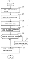
- Fig. 1 is a flowchart of a teaching operation to be executed in a teaching method for palletizing of the present invention.
- each of numerals following S denotes a step number.
- the palletizing operation program can easily be created.
- the stack pattern is a rectangular prism in the foregoing explanation, a stack pattern of a cylindrical prism may be also selected. In this case, two points, i.e., the center of the top face of the cylindrical prism and a point on the circumference of the bottom face of the prism are taught, so that the robot control unit can create a palletizing operation program.
- the palletizing operation program is created on the basis of the work coordinate system, two taught points of the workpiece array configuration, etc., so that the teaching operation is simplified as compared with the conventional manner in which four or five points must be taught. As a result, it is possible to shorten time required for setup, rearrangement, etc. of a production line, or the like.
Landscapes
- Engineering & Computer Science (AREA)
- Robotics (AREA)
- Mechanical Engineering (AREA)
- Numerical Control (AREA)
- Manipulator (AREA)
Abstract
Un modèle d'empilement correspondant à un agencement de pièces (50) est préalablement préparé dans le système de commande de robot (10). Au cours de l'apprentissage, un système de coordonnées de pièces est tout d'abord établi (S1), un modèle d'empilement correspondant à l'agencement de pièces est choisi (S2), des données d'agencement relatives à l'agencement de pièces sont ensuite introduites (S3), et deux points de l'agencement de pièces sont appris (S4). Le système de commande de robot (10) génère, à partir des données, un programme d'éxecution pour la palettisation.
Applications Claiming Priority (2)
| Application Number | Priority Date | Filing Date | Title |
|---|---|---|---|
| JP41457690A JPH04229308A (ja) | 1990-12-27 | 1990-12-27 | パレタイジングの教示方法 |
| JP414576/90 | 1990-12-27 |
Publications (2)
| Publication Number | Publication Date |
|---|---|
| EP0519082A1 true EP0519082A1 (fr) | 1992-12-23 |
| EP0519082A4 EP0519082A4 (en) | 1993-02-24 |
Family
ID=18523039
Family Applications (1)
| Application Number | Title | Priority Date | Filing Date |
|---|---|---|---|
| EP19920901874 Withdrawn EP0519082A4 (en) | 1990-12-27 | 1991-12-26 | Method of teaching palletizing |
Country Status (3)
| Country | Link |
|---|---|
| EP (1) | EP0519082A4 (fr) |
| JP (1) | JPH04229308A (fr) |
| WO (1) | WO1992012470A1 (fr) |
Cited By (2)
| Publication number | Priority date | Publication date | Assignee | Title |
|---|---|---|---|---|
| DE19740775A1 (de) * | 1997-09-17 | 1999-03-18 | Focke & Co | Steuerungssystem für insbesondere Palettieranlagen mit Robotern |
| CN109318225A (zh) * | 2017-08-01 | 2019-02-12 | 中达电子零组件(吴江)有限公司 | 用于控制码垛机器人的方法、装置及系统 |
Families Citing this family (1)
| Publication number | Priority date | Publication date | Assignee | Title |
|---|---|---|---|---|
| CN110322746A (zh) * | 2019-08-07 | 2019-10-11 | 江苏汇博机器人技术股份有限公司 | 用于工业机器人技能鉴定的实训操作台 |
Family Cites Families (2)
| Publication number | Priority date | Publication date | Assignee | Title |
|---|---|---|---|---|
| JPS6126109A (ja) * | 1984-07-17 | 1986-02-05 | Hitachi Ltd | パレタイジング・ロボツト・システムにおけるテイ−チング方式 |
| JPS6472205A (en) * | 1987-09-14 | 1989-03-17 | Hitachi Ltd | Robot teaching method |
-
1990
- 1990-12-27 JP JP41457690A patent/JPH04229308A/ja active Pending
-
1991
- 1991-12-26 WO PCT/JP1991/001776 patent/WO1992012470A1/fr not_active Ceased
- 1991-12-26 EP EP19920901874 patent/EP0519082A4/en not_active Withdrawn
Cited By (2)
| Publication number | Priority date | Publication date | Assignee | Title |
|---|---|---|---|---|
| DE19740775A1 (de) * | 1997-09-17 | 1999-03-18 | Focke & Co | Steuerungssystem für insbesondere Palettieranlagen mit Robotern |
| CN109318225A (zh) * | 2017-08-01 | 2019-02-12 | 中达电子零组件(吴江)有限公司 | 用于控制码垛机器人的方法、装置及系统 |
Also Published As
| Publication number | Publication date |
|---|---|
| JPH04229308A (ja) | 1992-08-18 |
| WO1992012470A1 (fr) | 1992-07-23 |
| EP0519082A4 (en) | 1993-02-24 |
Similar Documents
| Publication | Publication Date | Title |
|---|---|---|
| US4659971A (en) | Robot controlling system | |
| US7002585B1 (en) | Graphic display apparatus for robot system | |
| EP0213531B1 (fr) | Système automatique de programmation pour un programme numérique utilisé dans une machine-outil d'usinage | |
| EP0188623B1 (fr) | Methode de reglage d'un systeme de coordonnees d'outil | |
| EP1749621B1 (fr) | Dispositif de programmation de robot | |
| US5341458A (en) | Method of and system for generating teaching data for robots | |
| US5282143A (en) | Method and system for machining a sculptured surface | |
| US5844806A (en) | Work processing stacking device | |
| EP0298128B1 (fr) | Controleur de robot | |
| EP0103428B1 (fr) | Dispositif de programmation pour une commande numérique | |
| EP0519082A1 (fr) | Procede d'apprentissage de la palettisation | |
| JP3116129B2 (ja) | 加工方法 | |
| US5773950A (en) | Program creating method for uniform-shape machining | |
| JP2836633B2 (ja) | 数値制御情報作成機能における加工工程決定装置 | |
| EP0181406A1 (fr) | Procede de commande d'un robot | |
| JPH05324034A (ja) | ロボットの制御方法 | |
| JPH06312347A (ja) | Nc加工機 | |
| JP2799463B2 (ja) | 工業用ロボットの作業点教示方法 | |
| JP3248081B2 (ja) | 切削軸の自動変更機能付き自動プログラム作成装置 | |
| JP3031769B2 (ja) | ロボットの動作確認方法 | |
| JPH0890232A (ja) | 作業ロボットの作業プログラム作成装置 | |
| JP2000305613A (ja) | 三次元レーザ加工機の工具補正方法 | |
| JP2663575B2 (ja) | プレイバックロボットの制御装置 | |
| JP2559081B2 (ja) | ティーチングデータ作成方法および装置 | |
| JP2804474B2 (ja) | 産業用ロボットにおけるティーチング方法 |
Legal Events
| Date | Code | Title | Description |
|---|---|---|---|
| PUAI | Public reference made under article 153(3) epc to a published international application that has entered the european phase |
Free format text: ORIGINAL CODE: 0009012 |
|
| 17P | Request for examination filed |
Effective date: 19920916 |
|
| AK | Designated contracting states |
Kind code of ref document: A1 Designated state(s): DE IT SE |
|
| A4 | Supplementary search report drawn up and despatched |
Effective date: 19930107 |
|
| AK | Designated contracting states |
Kind code of ref document: A4 Designated state(s): DE IT SE |
|
| 17Q | First examination report despatched |
Effective date: 19940412 |
|
| STAA | Information on the status of an ep patent application or granted ep patent |
Free format text: STATUS: THE APPLICATION IS DEEMED TO BE WITHDRAWN |
|
| 18D | Application deemed to be withdrawn |
Effective date: 19950117 |