EP0517455B1 - Procédé et dispositif d'essai non destructif pour des matériaux supraconducteurs - Google Patents
Procédé et dispositif d'essai non destructif pour des matériaux supraconducteurs Download PDFInfo
- Publication number
- EP0517455B1 EP0517455B1 EP92304974A EP92304974A EP0517455B1 EP 0517455 B1 EP0517455 B1 EP 0517455B1 EP 92304974 A EP92304974 A EP 92304974A EP 92304974 A EP92304974 A EP 92304974A EP 0517455 B1 EP0517455 B1 EP 0517455B1
- Authority
- EP
- European Patent Office
- Prior art keywords
- winding
- spool
- tape
- bifilar
- superconducting
- Prior art date
- Legal status (The legal status is an assumption and is not a legal conclusion. Google has not performed a legal analysis and makes no representation as to the accuracy of the status listed.)
- Expired - Lifetime
Links
- 239000000463 material Substances 0.000 title claims description 21
- 238000000034 method Methods 0.000 title claims description 16
- 238000011156 evaluation Methods 0.000 title claims description 10
- 238000004804 winding Methods 0.000 claims description 79
- 238000012360 testing method Methods 0.000 claims description 39
- 230000005672 electromagnetic field Effects 0.000 claims description 13
- 230000001066 destructive effect Effects 0.000 claims description 11
- 238000001816 cooling Methods 0.000 claims description 9
- 229910052734 helium Inorganic materials 0.000 claims description 7
- 239000001307 helium Substances 0.000 claims description 7
- SWQJXJOGLNCZEY-UHFFFAOYSA-N helium atom Chemical compound [He] SWQJXJOGLNCZEY-UHFFFAOYSA-N 0.000 claims description 7
- 239000007788 liquid Substances 0.000 claims description 6
- 238000010791 quenching Methods 0.000 claims description 5
- 238000009659 non-destructive testing Methods 0.000 claims description 2
- 239000002826 coolant Substances 0.000 claims 1
- 230000001105 regulatory effect Effects 0.000 claims 1
- 239000012212 insulator Substances 0.000 description 6
- 230000002950 deficient Effects 0.000 description 5
- 230000002411 adverse Effects 0.000 description 4
- 238000012956 testing procedure Methods 0.000 description 4
- 230000006872 improvement Effects 0.000 description 3
- 239000004593 Epoxy Substances 0.000 description 2
- 239000004020 conductor Substances 0.000 description 2
- 230000006378 damage Effects 0.000 description 2
- 230000007246 mechanism Effects 0.000 description 2
- 238000012986 modification Methods 0.000 description 2
- 230000004048 modification Effects 0.000 description 2
- 230000008569 process Effects 0.000 description 2
- 230000000171 quenching effect Effects 0.000 description 2
- 238000010998 test method Methods 0.000 description 2
- 230000007704 transition Effects 0.000 description 2
- RYGMFSIKBFXOCR-UHFFFAOYSA-N Copper Chemical compound [Cu] RYGMFSIKBFXOCR-UHFFFAOYSA-N 0.000 description 1
- 239000010949 copper Substances 0.000 description 1
- 229910052802 copper Inorganic materials 0.000 description 1
- 230000007547 defect Effects 0.000 description 1
- 239000011152 fibreglass Substances 0.000 description 1
- 238000005470 impregnation Methods 0.000 description 1
- 238000003754 machining Methods 0.000 description 1
- KJSMVPYGGLPWOE-UHFFFAOYSA-N niobium tin Chemical compound [Nb].[Sn] KJSMVPYGGLPWOE-UHFFFAOYSA-N 0.000 description 1
- 229910000657 niobium-tin Inorganic materials 0.000 description 1
- 238000004445 quantitative analysis Methods 0.000 description 1
- 230000000717 retained effect Effects 0.000 description 1
- 238000007619 statistical method Methods 0.000 description 1
- 239000002887 superconductor Substances 0.000 description 1
- 238000002604 ultrasonography Methods 0.000 description 1
Images


Classifications
-
- G—PHYSICS
- G01—MEASURING; TESTING
- G01R—MEASURING ELECTRIC VARIABLES; MEASURING MAGNETIC VARIABLES
- G01R33/00—Arrangements or instruments for measuring magnetic variables
- G01R33/12—Measuring magnetic properties of articles or specimens of solids or fluids
- G01R33/1238—Measuring superconductive properties
-
- G—PHYSICS
- G01—MEASURING; TESTING
- G01R—MEASURING ELECTRIC VARIABLES; MEASURING MAGNETIC VARIABLES
- G01R31/00—Arrangements for testing electric properties; Arrangements for locating electric faults; Arrangements for electrical testing characterised by what is being tested not provided for elsewhere
- G01R31/50—Testing of electric apparatus, lines, cables or components for short-circuits, continuity, leakage current or incorrect line connections
- G01R31/72—Testing of electric windings
-
- Y—GENERAL TAGGING OF NEW TECHNOLOGICAL DEVELOPMENTS; GENERAL TAGGING OF CROSS-SECTIONAL TECHNOLOGIES SPANNING OVER SEVERAL SECTIONS OF THE IPC; TECHNICAL SUBJECTS COVERED BY FORMER USPC CROSS-REFERENCE ART COLLECTIONS [XRACs] AND DIGESTS
- Y10—TECHNICAL SUBJECTS COVERED BY FORMER USPC
- Y10S—TECHNICAL SUBJECTS COVERED BY FORMER USPC CROSS-REFERENCE ART COLLECTIONS [XRACs] AND DIGESTS
- Y10S505/00—Superconductor technology: apparatus, material, process
- Y10S505/725—Process of making or treating high tc, above 30 k, superconducting shaped material, article, or device
- Y10S505/726—Measuring or testing of superconducting property
Definitions
- This invention relates to a non-destructive apparatus and method for evaluating the properties of superconducting materials.
- Such structures of this type generally allow the superconducting material to be tested without having to destroy the material or throw the material away.
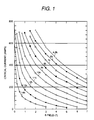
- the current that is run through the short sample is varied to see at what value the short sample quenches, and the current is compared with the results of a graph much like the one in Figure 1 where current in amps is plotted against electromagnetic field strength (B). If the field strength is known and the temperature value is known, then the operator can extrapolate from the graph as to whether the short sample quenched is in agreement with the current at which a good tape should quench, given the same field strength and temperature values. If the short sample test falls within the guidelines as set forth in Figure 1 for a particular current, electromagnetic field, and temperature, then it is assumed that the entire tape is good. If the short sample does not fall within the guidelines, then it is assumed that the entire tape is defective. Such arrangements have been described in JOURNAL OF PHYSICS E. SCIENTIFIC INSTRUMENTS Vol.20 No. 5 May 1987 pages 516-520 and CRYOGENICS Vol. 25 No. 8 (1985), pages 457-461.
- the short sample method is a general way to determine if the entire tape is good or defective, the method is destructive because the sample must first be cut down and then thrown away after the testing. Also, the short sample only tests a little part of the entire tape, and maybe the rest of the tape is not defective even if the sample proves to be defective. Therefore, a more advantageous system, then, would be presented if the test could be performed in a non-destructive manner while testing a substantially longer portion of the tape or the entire tape.
- a long sample, destructive evaluation system was developed.
- a long sample of superconducting material typically, one inch wide is cut into 7 strips with each strip being approximately 3mm in width.
- the outer two strips along each edge of the material are then epoxy impregnated according to a conventional practice. The outer two strips were selected because it was determined by conventional statistical analysis that the edges of the material are the places where defects in the material are most likely to be located.
- the long sample has to be impregnated so that the sample could withstand the electromagnetic forces experienced by it when the current was run through the long sample.
- the impregnation provided the needed support for the sample so that the sample would not mechanically fail due to the current passing through it.
- These impregnated coils were then tested by using the same test procedure used to test the short samples except that a background electromagnetic field is not necessary. If the long samples fell within the guidelines as shown in Figure 1, it was assumed that the entire tape was good. If the long sample was bad, it was assumed that the entire tape was bad. This long sample test provided a more accurate test as to the quality of the entire tape but the long sample still had to be destroyed because it was impregnated. Consequently, a still more advantageous system, then, would be presented if the advantageous longer samples were used but without having to destroy the samples.
- Non-destructive tests for evaluating the quality of superconducting materials have been developed but, only for use in a non-cryogenic atmosphere, however. Beyond the obvious test of visually inspecting the tape, a conventional eddy current test or an ultrasound test was performed on the sample. While these tests pointed out obvious flaws in the tape, they did not test the actual superconducting characteristics of the tape because the superconducting characteristics should be determined at cryogenic temperatures. Consequently, a further more advantageous system, then, would be presented if the advantageous longer samples were used but were tested in an atmosphere in which a more accurate determination as to the quality of the sample could be attained.
- an apparatus for evaluating and non destructive testing the superconducting quality of a superconducting material formed into a winding comprising;
- the spool means includes an S-cut which allows the winding to be wound on the spool without having to cut the winding and which also allows the winding to be easily unwound onto another-spool without adversely affecting the mechanical properties of the winding.
- the bifilar winding is used so that the currents which flow in opposite directions between adjacent tapes in a bifilar winding, cancel each other out which results in no net inductance in the bifilar winding which, in turn, eliminates the adverse electromagnetic forces usually found in superconducting coils.
- the cooling means is liquid helium.
- the evaluation means imposes a known magnetic field in the winding and by either varying the current or the temperature one can determine if the entire winding is defective or not by comparing the results attained from the test with the predetermined results plotted on a well-known graph for a good superconducting tape.
- substantially the entire winding can be non-destructively evaluated in an atmosphere which will provide an accurate determination as to the superconducting qualities of the winding.
- the preferred superconducting materials evaluation system offers the following advantages: easy assembly; good stability; good durability; lack of destruction of the sample, increased size of the sample measured; good economy; improved testing conditions; and high strength for safety.
- these factors of lack of destruction of the sample, increased sample size and improved testing conditions are optimized to an extent considerably higher than heretofore achieved in prior, known superconducting material evaluation systems.
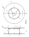
- Spool 2 includes flanges 4 and 14, bobbin 6, conventional fasteners 8, 12, and 16, and S-cut plate 10.
- Flanges 4 and 14, bobbin 6 and plate 10, preferably, are constructed of any suitable fiberglass filled epoxy material or copper.
- Flange 4 is rigidly attached to one end of bobbin 6 by fasteners 8.
- S-cut plate 10 is rigidly attached to the other end of bobbin 6 by fasteners 12.
- Flange 14 is rigidly attached to bobbin 6 and plate 10 by fasteners 16.
- plate 10 includes groove 18.
- Groove 18, preferably, is milled in plate 10 by conventional machining techniques to a depth of approximately 4mm.
- Groove 18 is provided to allow the continuous superconducting tape 24 (Fig. 3a) to be captured by flange 14 and which also provides the minimum radius to avoid damaging the tape and allows the tape to be bifilarly wound.
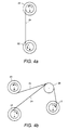
- Figures 3a-3c shows how spool 2 is bifilarly wound with superconducting tape 24 coming from a supply spool or superconducting tape 30 coming from an insulator.
- supply spools 20,22 which, typically, are wound with a niobium-tin, hereinafter referred to as Nb-Sn, tape conductor 24.
- Nb-Sn niobium-tin
- the ends of conductor 24 from spools 20,22 are, initially, welded together with either a conventional pig tail weld or an in-line weld and fed as a bifilar tape 28 over pulley 26.
- the bifilar tape 28 is attached to bobbin 6 ( Figure 2a) and in the case of in-line weld tape 28 is attached by conventional fastening techniques to groove 18 ( Figures 2b) in bifilar spool 2.
- Spool 2 is rotated clockwise by a conventional rotating mechanism (not shown) along arrow A.
- the rotation of spool 2 causes supply spools 20,22 to also rotate along the same direction A which, in turn, causes tape 24 to come off of spools 20,22, form bifilar tape 28, and become wound on spool 2 to form winding 37.
- a sufficient amount of tape preferably, 1000 to 30,000 feet, have been wound on spool 2, the winding process is stopped.
- Figure 3b shows how tapes 24 from a supply spool and 30 from a conventional insulator form a bifilar tape 32 which is wound on spool 2 to form winding 37 according to the same technique as used in Figure 3a.
- Figure 3c depicts the winding of bifilar tape 34 on spool 2 to form winding 37.
- Tape 34 is, preferably, constructed of two layers of tape 30 coming from insulator. It is to be understood that the winding techniques as shown in Figures 3a-3c require the use of a pig tail weld or in-line weld.
- Figures 4a and 4b illustrate another embodiment for winding tape 24 from spools or insulator 30 on spool 2.
- tape 24 will be discussed in this embodiment.
- a pig tail weld or in-line weld is not needed because in order to wind tape 24 on spool 2, approximately one-half of tape 24 from supply spool 20 is wound onto supply spool 22 in a counterclockwise direction along arrow B ( Figure 4a).
- a portion of tape 24 which spans between supply spools 20,22 is run over pulley 26 and placed in groove 18 ( Figure 2b) in spool 2 ( Figure 4b).
- FIGs 5a and 5b illustrate two methods for testing the superconducting quality of bifilar winding 37.
- a bifilar spool 2 which contains a superconducting winding 37 is placed in a container 46.
- Container 46 also holds a conventional electro-magnetic field generating superconductive coil 40, liquid helium 44, and a lid 48.
- Spool 2 and coil 40 are electrically connected to a conventional control mechanism (not shown) by wires 38,42, respectively.
- coil 40 is activated and a predetermined electromagnetic field or B field, typically, having a value of 0-7 Tesla, is placed on coil 40.
- B field typically, having a value of 0-7 Tesla
- the temperature of the spool 2 can be varied and the current through winding 37 can be kept constant, typically, at between 400 to 500 amps, until winding 37 quenches.
- the temperature at which coil 37 quenches is compared with the values given in Figure 1 for a given field strength and current value to determine if winding 37 is good. It is to be understood that the temperature could be kept constant and the current varied until coil 37 quenched in order to achieve the same quantitative analysis as to the superconducting quality of winding 37.
- Figure 5b shows another testing method for evaluating the superconducting quality of a superconducting tape.
- a bifilar spool 2 having a superconductor winding 37 is placed in container 46 along with liquid helium 44.
- either the current or temperature is varied until winding 37 quenches and the results are compared with Figure 1.
- electromagnetic field value equals 0 because no field is present in container 46.
- the testing apparatus embodied in Figures 5a and 5b are an improvement over the prior testing procedures because winding 37 operates most efficiently at cryogenic temperatures so it is apparent that the winding should be tested at cryogenic temperatures to determine if the winding is good.
- the preferred method of testing is to use the apparatus set forth in Figure 5b. This is because when coil 40 creates an electromagnetic field in winding 37, the field across the entire winding 37 is not uniform. Thus, when winding 37 quenches the quenching current and temperatures are fairly accurately determined but, it is difficult to determine at which point on winding 37 the winding was, for example, at a field value of 4T, when the quenching occurred. Assuming that 4T was the field value on coil 40. Consequently, in order to avoid the possible problems associated with the apparatus in Figure 5a, Figure 5b is preferred because B always equals zero which eliminates one parameter.
- testing system embodied in Figure 5a may be used if, for example, it is difficult to stabilize the temperature within container 46 or if there are any characteristics of winding 37 or the joints in winding 37 which would be specific to the field created by coil 40.
- Figure 6 illustrates yet another system for testing the quality of the tapes.
- This system is similar to the apparatus embodied in Figure 5b, in that, no field is being used in container 46. However, in this particular testing embodiment, several windings 37a, 37b, 37c are placed in container 46.
- Container 46 also includes liquid helium 44. Spools 2a,2b,2c are retained in container 46 by a conventional holder 48. Holder 48 should be constructed as to allow helium 44 or its vapor to contact windings 37a, 37b, 37c but also strong enough to support spools 2a,2b,2c.
- holder 48 should allow the operator to be able to test the quality of winding 37a without adversely affecting the superconducting characteristics of windings 37b and 37c.
- the testing procedure for testing windings 37a, 37b, 37c is the same as discussed with reference to Figure 5b however, it is preferred that winding 37a be tested first then followed by winding 37b and, finally, winding 37c. After the quality of windings 37a, 37b and 37c is determined, spools 2a,2b,2c are removed.
- Figure 7 illustrates how winding 37 is unrolled from bifilar spool 2 after winding 37 has been tested and winding 37 was found to be good.
- tapes 24a and 24b are separated from bifilar winding 37.
- Tape 24a is then run over a conventional pulley 50 and wound on a conventional magnet cartridge 54.
- Tape 24b is placed on transition spool 52 and wound on spool 52 so that spool 52 rotates along arrow E.
- spool 52 is rotated by a conventional rotating device (not shown) in a counterclockwise direction along arrow E and cartridge 54 is rotated by a conventional rotating device (not shown) in a clockwise direction along arrow C, winding 37 becomes unwound from spool 2.
- tape 24a, 24b is unwound from spool 2
- cartridge 54 continues to rotate such that tape 24b is now being unwound directly from transition spool 52 so that spool 52 now rotates along arrow E.
- Tape 24b is capable of being directly unwound by cartridge 54 due to the groove 18 ( Figure 2b) in spool 2.
- Figure 8 is a graphical representation of the results from Figure 1 for a 48A/mm conducting tape using temperature in degrees K as the abscissa and current in amps as the ordinate.
- Figure 8 shows that for the same conditions, namely, the same B, T and current values, the 58A/mm tape is a better conducting tape because it quenches at a higher temperature and a higher current than a 48A/mm tape.
Landscapes
- Physics & Mathematics (AREA)
- General Physics & Mathematics (AREA)
- Engineering & Computer Science (AREA)
- Power Engineering (AREA)
- Condensed Matter Physics & Semiconductors (AREA)
- Investigating Or Analyzing Materials By The Use Of Magnetic Means (AREA)
- Measuring Magnetic Variables (AREA)
- Testing Electric Properties And Detecting Electric Faults (AREA)
Claims (8)
- Dispositif pour l'évaluation et l'essai non destructif des qualités de supraconduction d'un matériau supraconducteur présenté sous forme d'enroulement (37), le dispositif comprenant :un moyen servant à enrouler un enroulement bifilaire (37) sur un rouleau (2) sur une longueur d'au moins 30480 cm pour former une bobine réutilisable;un moyen de refroidissement cryogénique (44) refroidissant directement la bobine entière formée sur le rouleau;un moyen de maintien (46) servant à supporter le rouleau (2) et le moyen de refroidissement (44);des moyens d'évaluation et d'essai comportant un moyen de détection de température et un moyen de détermination de transition pour déterminer quand l'enroulement effectue sa transition de manière non destructive; etun moyen servant à dérouler l'enroulement bifilaire (37) du rouleau (2) après achèvement de l'essai.
- Dispositif selon la revendication 1, dans lequel le rouleau comporte une rainure en S dans laquelle est située une partie de l'enroulement.
- Dispositif selon la revendication 1 ou 2, dans lequel le moyen de refroidissement est de l'hélium liquide (44).
- Dispositif selon l'une quelconque des revendications précédentes, dans lequel le dispositif inclut un moyen (40) de production de champ magnétique.
- Dispositif selon la revendication 4, dans lequel le rouleau, le moyen de refroidissement (44) et le moyen (40) de production de champ magnétique sont disposés dans un moyen de maintien commun.
- Dispositif selon l'une quelconque des revendications précédentes, dans lequel le moyen de maintien comprend un conteneur (46) et un premier récipient situé à l'intérieur du conteneur.
- Procédé d'évaluation non destructive des qualités de supraconduction d'un matériau supraconducteur, comprenant les étapes consistant à :enrouler le matériau en un enroulement bifilaire (37) sur un rouleau (2) sur une longueur d'au moins 30480 cm pour former une bobine réutilisable;placer le rouleau entier (2) dans un conteneur (46) comportant un agent de refroidissement cryogénique pour refroidir directement l'enroulement (37) sur le rouleau (2);réguler la température de l'enroulement (37);observer et enregistrer un courant dans l'enroulement (37) jusqu'à ce que l'enroulement (37) subissent la transition de manière non destructive; etdérouler l'enroulement bifilaire (37) du rouleau (2) après achèvement de l'essai.
- Procédé selon la revendication 7, comprenant l'étape consistant à :placer un champ magnétique électromagnétique prédéterminé au voisinage proche de l'enroulement (37).
Applications Claiming Priority (2)
| Application Number | Priority Date | Filing Date | Title |
|---|---|---|---|
| US710595 | 1991-06-05 | ||
| US07/710,595 US5140266A (en) | 1991-06-05 | 1991-06-05 | Apparatus and method for the non-destructive evaluation of a bifilar superconducting winding |
Publications (3)
| Publication Number | Publication Date |
|---|---|
| EP0517455A2 EP0517455A2 (fr) | 1992-12-09 |
| EP0517455A3 EP0517455A3 (en) | 1993-05-19 |
| EP0517455B1 true EP0517455B1 (fr) | 1999-09-08 |
Family
ID=24854699
Family Applications (1)
| Application Number | Title | Priority Date | Filing Date |
|---|---|---|---|
| EP92304974A Expired - Lifetime EP0517455B1 (fr) | 1991-06-05 | 1992-06-01 | Procédé et dispositif d'essai non destructif pour des matériaux supraconducteurs |
Country Status (4)
| Country | Link |
|---|---|
| US (1) | US5140266A (fr) |
| EP (1) | EP0517455B1 (fr) |
| JP (1) | JPH0823550B2 (fr) |
| DE (1) | DE69229933T2 (fr) |
Families Citing this family (11)
| Publication number | Priority date | Publication date | Assignee | Title |
|---|---|---|---|---|
| US5227720A (en) * | 1992-04-02 | 1993-07-13 | General Electric Company | Apparatus and method using a bifilar coil with an integrated loop/switch for resistance measurement of superconductors |
| JP3705861B2 (ja) * | 1996-03-21 | 2005-10-12 | 株式会社日立メディコ | 超電導磁石装置及びその着磁調整方法 |
| US6275365B1 (en) * | 1998-02-09 | 2001-08-14 | American Superconductor Corporation | Resistive fault current limiter |
| US6900714B1 (en) * | 2004-06-30 | 2005-05-31 | General Electric Company | System and method for quench and over-current protection of superconductor |
| JP5696941B2 (ja) * | 2011-08-08 | 2015-04-08 | 住友電気工業株式会社 | 臨界電流の測定方法 |
| JP2013036844A (ja) * | 2011-08-08 | 2013-02-21 | Sumitomo Electric Ind Ltd | ケーブルコアの試験方法 |
| JP2013036841A (ja) * | 2011-08-08 | 2013-02-21 | Sumitomo Electric Ind Ltd | 超電導ケーブル用ケーブルコアの試験方法 |
| JP5696942B2 (ja) * | 2011-08-08 | 2015-04-08 | 住友電気工業株式会社 | 超電導ケーブル用ケーブルコアの試験方法 |
| JP2013036842A (ja) * | 2011-08-08 | 2013-02-21 | Sumitomo Electric Ind Ltd | 超電導ケーブル用ケーブルコアの試験方法、および冷却容器 |
| KR101296810B1 (ko) * | 2011-11-03 | 2013-08-14 | 한국전기연구원 | 멀티 초전도 코일의 특성 실험 장치 |
| CN104718459A (zh) * | 2012-10-11 | 2015-06-17 | 住友电气工业株式会社 | 用于检测超导电缆用电缆芯的方法和冷却容器 |
Family Cites Families (6)
| Publication number | Priority date | Publication date | Assignee | Title |
|---|---|---|---|---|
| JPS61111588A (ja) * | 1984-11-05 | 1986-05-29 | Toshiba Corp | 超電導線の臨界電流測定装置 |
| JPS6336506A (ja) * | 1986-07-31 | 1988-02-17 | Hitachi Ltd | 超電導巻線の常電導転移検出法 |
| JPS6425488A (en) * | 1987-07-22 | 1989-01-27 | Toshiba Corp | Superconduction detector |
| US4803456A (en) * | 1987-12-22 | 1989-02-07 | General Electric Company | Superconductive switch |
| US4904970A (en) * | 1988-02-17 | 1990-02-27 | General Electric Company | Superconductive switch |
| DE69114344T2 (de) * | 1990-04-27 | 1996-06-05 | Railway Technical Res Inst | Schalter zur Kontrolle des Stromflusses in Supraleitern. |
-
1991
- 1991-06-05 US US07/710,595 patent/US5140266A/en not_active Expired - Fee Related
-
1992
- 1992-06-01 DE DE69229933T patent/DE69229933T2/de not_active Expired - Fee Related
- 1992-06-01 EP EP92304974A patent/EP0517455B1/fr not_active Expired - Lifetime
- 1992-06-04 JP JP4143935A patent/JPH0823550B2/ja not_active Expired - Fee Related
Also Published As
| Publication number | Publication date |
|---|---|
| EP0517455A2 (fr) | 1992-12-09 |
| EP0517455A3 (en) | 1993-05-19 |
| US5140266A (en) | 1992-08-18 |
| JPH05249213A (ja) | 1993-09-28 |
| DE69229933T2 (de) | 2000-05-18 |
| JPH0823550B2 (ja) | 1996-03-06 |
| DE69229933D1 (de) | 1999-10-14 |
Similar Documents
| Publication | Publication Date | Title |
|---|---|---|
| EP0517455B1 (fr) | Procédé et dispositif d'essai non destructif pour des matériaux supraconducteurs | |
| US3976934A (en) | Method and apparatus for the continuous, contactless testing of a long conductor which consists at least partially of superconductive material | |
| US4922200A (en) | Apparatus for measuring the hysteresis loop of magnetic film | |
| Wang et al. | A novel AC-MFL probe based on the parallel cables magnetizing technique | |
| EP0641433B1 (fr) | Appareil pour l'examen non destructif de materiaux dielectriques/magnetiques | |
| US5218296A (en) | Method and apparatus for determining at least one characteristic of a superconductive film | |
| US20200200841A1 (en) | Method for evaluating the electrical properties of a hts superconductor | |
| Tominaka et al. | Electrical properties of superconducting joint between composite conductors | |
| US4132949A (en) | Method and apparatus for the continuous, contactless testing of an elongated conductor which consists at least partially of superconductive material | |
| KR920000712B1 (ko) | 직접 검사 가능한 초전도체 접속자 및 상기 접속자를 이용한 초전도성 자석 조립 방법 | |
| US5907102A (en) | System and method for performing tensile stress-strain and fatigue tests | |
| Frankel | Model for flux trapping and shielding by tubular superconducting samples in transverse fields | |
| Lee et al. | Determining the absolute value of penetration depth of large area films | |
| Arai et al. | Acoustic emission and normal components in an alternating current superconducting coil | |
| Desportes et al. | General Design and Conductor Study for the" ALEPH" Superconducting Solenoid | |
| Benvenuti et al. | Magnetic flux trapping in superconducting niobium | |
| JPH1123536A (ja) | 金属材料の疲労診断方法 | |
| WO2016027522A1 (fr) | Procédé et appareil pour inspecter une tige de fil supraconductrice et procédé de fabrication de tige de fil supraconductrice | |
| Rupp | Localization of defects in multifilamentary Nb 3 Sn conductors by an inductive procedure | |
| JPH1130607A (ja) | 導体非破壊検査用装置 | |
| JPS61111588A (ja) | 超電導線の臨界電流測定装置 | |
| Ghosh et al. | Magnetization and critical currents of NbTi wires with fine filaments | |
| JP3390544B2 (ja) | 微小部物性情報測定装置および微小部物性情報測定方法 | |
| WO1998020335A1 (fr) | Procede et appareil permettant de mesurer directement la resistance de cables metalliques | |
| Doyle | Fluxon pinning and geometrical Effects in a type II superconductor |
Legal Events
| Date | Code | Title | Description |
|---|---|---|---|
| PUAI | Public reference made under article 153(3) epc to a published international application that has entered the european phase |
Free format text: ORIGINAL CODE: 0009012 |
|
| AK | Designated contracting states |
Kind code of ref document: A2 Designated state(s): DE GB NL |
|
| PUAL | Search report despatched |
Free format text: ORIGINAL CODE: 0009013 |
|
| AK | Designated contracting states |
Kind code of ref document: A3 Designated state(s): DE GB NL |
|
| 17P | Request for examination filed |
Effective date: 19931102 |
|
| 17Q | First examination report despatched |
Effective date: 19951220 |
|
| GRAG | Despatch of communication of intention to grant |
Free format text: ORIGINAL CODE: EPIDOS AGRA |
|
| GRAG | Despatch of communication of intention to grant |
Free format text: ORIGINAL CODE: EPIDOS AGRA |
|
| GRAH | Despatch of communication of intention to grant a patent |
Free format text: ORIGINAL CODE: EPIDOS IGRA |
|
| GRAH | Despatch of communication of intention to grant a patent |
Free format text: ORIGINAL CODE: EPIDOS IGRA |
|
| GRAA | (expected) grant |
Free format text: ORIGINAL CODE: 0009210 |
|
| AK | Designated contracting states |
Kind code of ref document: B1 Designated state(s): DE GB NL |
|
| REF | Corresponds to: |
Ref document number: 69229933 Country of ref document: DE Date of ref document: 19991014 |
|
| PLBE | No opposition filed within time limit |
Free format text: ORIGINAL CODE: 0009261 |
|
| STAA | Information on the status of an ep patent application or granted ep patent |
Free format text: STATUS: NO OPPOSITION FILED WITHIN TIME LIMIT |
|
| 26N | No opposition filed | ||
| REG | Reference to a national code |
Ref country code: GB Ref legal event code: IF02 |
|
| PGFP | Annual fee paid to national office [announced via postgrant information from national office to epo] |
Ref country code: NL Payment date: 20030522 Year of fee payment: 12 |
|
| PGFP | Annual fee paid to national office [announced via postgrant information from national office to epo] |
Ref country code: GB Payment date: 20030528 Year of fee payment: 12 |
|
| PGFP | Annual fee paid to national office [announced via postgrant information from national office to epo] |
Ref country code: DE Payment date: 20030630 Year of fee payment: 12 |
|
| PG25 | Lapsed in a contracting state [announced via postgrant information from national office to epo] |
Ref country code: GB Free format text: LAPSE BECAUSE OF NON-PAYMENT OF DUE FEES Effective date: 20040601 |
|
| PG25 | Lapsed in a contracting state [announced via postgrant information from national office to epo] |
Ref country code: NL Free format text: LAPSE BECAUSE OF NON-PAYMENT OF DUE FEES Effective date: 20050101 Ref country code: DE Free format text: LAPSE BECAUSE OF NON-PAYMENT OF DUE FEES Effective date: 20050101 |
|
| GBPC | Gb: european patent ceased through non-payment of renewal fee | ||
| NLV4 | Nl: lapsed or anulled due to non-payment of the annual fee |
Effective date: 20050101 |