EP0515888B1 - Support and pointing arrangement for antennes or telescopes - Google Patents
Support and pointing arrangement for antennes or telescopes Download PDFInfo
- Publication number
- EP0515888B1 EP0515888B1 EP92107916A EP92107916A EP0515888B1 EP 0515888 B1 EP0515888 B1 EP 0515888B1 EP 92107916 A EP92107916 A EP 92107916A EP 92107916 A EP92107916 A EP 92107916A EP 0515888 B1 EP0515888 B1 EP 0515888B1
- Authority
- EP
- European Patent Office
- Prior art keywords
- arrangement
- legs
- telescopes
- telescope
- frame
- Prior art date
- Legal status (The legal status is an assumption and is not a legal conclusion. Google has not performed a legal analysis and makes no representation as to the accuracy of the status listed.)
- Expired - Lifetime
Links
Images

Classifications
-
- H—ELECTRICITY
- H01—ELECTRIC ELEMENTS
- H01Q—ANTENNAS, i.e. RADIO AERIALS
- H01Q1/00—Details of, or arrangements associated with, antennas
- H01Q1/27—Adaptation for use in or on movable bodies
- H01Q1/28—Adaptation for use in or on aircraft, missiles, satellites, or balloons
- H01Q1/288—Satellite antennas
-
- H—ELECTRICITY
- H01—ELECTRIC ELEMENTS
- H01Q—ANTENNAS, i.e. RADIO AERIALS
- H01Q1/00—Details of, or arrangements associated with, antennas
- H01Q1/12—Supports; Mounting means
- H01Q1/125—Means for positioning
Definitions
- the invention relates to an arrangement for supporting and aligning antennas or telescopes, in particular for space applications, according to the preamble of patent claim 1.
- the weight for the arrangement for supporting and aligning the telescope can be significantly reduced.
- the alignment mechanism is based on changing the length of the six legs of the Hexapod. If the length of the legs can be changed over a large area, the support and alignment arrangement, the hexapod, can also be used as an extension unit for extending the telescope. To do this, change the length of the six legs at the same time.
- the advantage of using a frame in the form of a hexapod not only to support and align a telescope, but also to use the frame as an extension unit, is that in applications with unfavorable satellite geometries, the telescope can be extended far and then no longer by other structures in its viewing angle is restricted on the satellite.
- a starting position is provided according to the invention, in which the alignment mechanism is blocked in a defined manner (English: launch lock). According to the invention, this is achieved by internally bracing the individual legs.
- FIG. 1 An arrangement according to the invention, such as could be mounted on a satellite platform 2, for example, is shown in FIG.
- a telescope 1 is attached to a rigid support plate 10 via a rotation and deflection mechanism 5.
- the outline of the carrier plate 10 corresponds to an equilateral hexagon.
- An optical bench 3 is attached below the carrier plate.
- One end of a leg 6 is attached to each of the six corners of the carrier plate.
- the six legs are adjustable in length. They are each attached to the carrier plate 10 via a ball joint. At the other end, the legs 6 are combined in pairs and via ball joints with the satellite platform 2, which Base area forms, connected.
- the six adjustable legs form the hexapod frame.
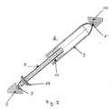
- the structure of the individual legs is shown in Figure 2.
- a leg 6 consists of an inner tube 8 and an outer tube 9.
- the inner tube can be moved with respect to the outer tube by piezoelectric linear motors 11. These are attached to the outer tube and move on the smooth, precisely machined outer surface of the inner tube 8. At the ends of the legs 6 there is in each case a ball joint 7.
- the legs are on one side with the satellite platform 2 and on the other side connected to the support plate 10 which carries the telescope 1.
- the inner tube 8 of the legs on the outer surface of which the piezoelectric linear motors, also called inchworm motors, move, is advantageously a PEEK tube and has a very good sliding surface.
- the outer tube 9 is braced against the stop disk 14 by means of the piezoelectric linear motors. This significantly increases the strength of the overall structure during the starting process.
- the surface of the stop disk 14 can be coated with steel wool, for example, in order to ensure high damping, friction and elasticity.
Description
Die Erfindung betrifft eine Anordnung zum Stützen und Ausrichten von Antennen oder Teleskopen, insbesondere für Weltraumanwendungen, nach dem Oberbegriff des Patentanspruches 1.The invention relates to an arrangement for supporting and aligning antennas or telescopes, in particular for space applications, according to the preamble of
Eine gattungsgemäße Anordnung ist bereits bekannt aus "Das Hexapod-Teleskop - ein Prototyp für das Deutsche Großteleskop" von Theodor Schmidt-Kaler in Spektrum der Wissenschaft, Mai 1991, Seite 18 bis 22. Das Nachführungssystem dieses Teleskops soll das mechanische Grundprinzip nutzen, daß ein starrer Körper genau sechs Freiheitsgrade der Bewegung hat und die Tragestruktur des Hauptspiegels wird daher durch sechs Beine mit dem Fundament des Teleskops verbunden. Man kann durch Verlängern bzw. Verkürzen der Beine und damit durch Veränderung der Neigungswinkel gerade sechs Freiheitsgrade realisieren.A generic arrangement is already known from "The Hexapod Telescope - A Prototype for the German Large Telescope" by Theodor Schmidt-Kaler in Spectrum of Science, May 1991, pages 18 to 22. The tracking system of this telescope is to use the basic mechanical principle that a rigid body has exactly six degrees of freedom of movement and the supporting structure of the main mirror is therefore connected to the base of the telescope by six legs. By lengthening or shortening the legs and thus by changing the angle of inclination, just six degrees of freedom can be achieved.
Eine weitere Anordnung zum Stützen und Ausrichten von Antennen mit einem Gestell in Form eines Hexapods, entsprechend dem Oberbegriff des Patentanspruches 1 ist aus der EP 02 66 026 A1 bekannt.Another arrangement for supporting and aligning antennas with a frame in the form of a hexapod, according to the preamble of
Ausgehend von diesem Stand der Technik ist es Aufgabe der Erfindung, eine Anordnung zum Stützen und Ausrichten von Teleskopen anzugeben, die für den Einsatz auf Satelliten besonders geeignet ist.Based on this prior art, it is an object of the invention to provide an arrangement for supporting and aligning telescopes that are suitable for use on satellites is particularly suitable.
Die Aufgabe wird mit den Merkmalen des Patentanspruches 1 gelöst. Vorteilhafte Weiterbildungen sind in den Unteransprüchen angegeben.The object is achieved with the features of
Für den Einsatz von Stütz- und Ausrichtmechanismen für Teleskope auf Satelliten ist es von besonderer Bedeutung, daß die Systeme von geringem Gewicht und Volumen sind. Außerdem werden hohe Anforderungen an die Genauigkeit des Ausrichtmechanismus gestellt. Da der freie Platz auf einem Satelliten gering ist, kann es vorkommen, daß der Sichtbereich des Teleskops durch andere Aufbauten auf den Satelliten beschränkt wird. Dies kann sich äußerst nachteilig auswirken.For the use of support and alignment mechanisms for telescopes on satellites, it is particularly important that the systems are light in weight and volume. In addition, high demands are placed on the accuracy of the alignment mechanism. Since the free space on a satellite is small, it can happen that the field of view of the telescope is restricted by other structures on the satellite. This can be extremely detrimental.
Durch den Einsatz einer Tragestruktur in Form eines Hexapods kann das Gewicht für die Anordnung zum Stützen und Ausrichten des Teleskops wesentlich herabgesetzt werden. Der Ausrichtmechanismus basiert auf der Längenänderung der sechs Beine des Hexapods. Wenn die Länge der Beine über einen großen Bereich veränderbar ist, so kann die Stütz- und Ausrichtanordnung, das Hexapod, auch als Ausfahreinheit zum Ausfahren des Teleskops eingesetzt werden. Dazu ändert man die Länge der sechs Beine gleichzeitig. Ein Gestell in Form eines Hexapods nicht nur zum Stützen und Ausrichten eines Teleskops einzusetzen, sondern das Gestell auch als Ausfahreinheit einsetzen, bringt den Vorteil, daß bei Applikationen auf ungünstigen Satellitengeometrien das Teleskop weit ausgefahren werden kann und dann in seinem Sichtwinkel nicht mehr durch andere Aufbauten auf dem Satelliten eingeschränkt ist.By using a support structure in the form of a hexapod, the weight for the arrangement for supporting and aligning the telescope can be significantly reduced. The alignment mechanism is based on changing the length of the six legs of the Hexapod. If the length of the legs can be changed over a large area, the support and alignment arrangement, the hexapod, can also be used as an extension unit for extending the telescope. To do this, change the length of the six legs at the same time. The advantage of using a frame in the form of a hexapod not only to support and align a telescope, but also to use the frame as an extension unit, is that in applications with unfavorable satellite geometries, the telescope can be extended far and then no longer by other structures in its viewing angle is restricted on the satellite.
Neben dem geringen Gewicht des Ausrichtmechanismus spielt auch der Leistungsverbrauch einen solchen Mechanismus, insbesondere bei Weltraumanwendungen, eine sehr große Rolle. Durch den erfindungsgemäßen Einsatz von piezoelektrischen Linearmotoren zur Betätigung von Ausrichtmechanismus und Ausfahreinheit kann eine Reduzierung des Leistungsverbrauchs erreicht werden. Der Einsatz von Inchworm-Motoren (bekannt aus US 39 02 084) hat den Vorteil, daß diese ohne Betriebsspannung blockiert, also im Ruhezustand sind.In addition to the low weight of the alignment mechanism, the power consumption of such a mechanism also plays a very large role, particularly in space applications. By the The use of piezoelectric linear motors according to the invention for actuating the alignment mechanism and extension unit can reduce the power consumption. The use of inchworm motors (known from US 39 02 084) has the advantage that they are blocked without operating voltage, that is to say in the idle state.
Für die speziellen Anforderungen eines Ausrichtmechanismus auf einem Satelliten, der auf einer Trägerrakete befestigt die Startbedingungen erfüllen muß, ist erfindungsgemäß eine Startposition vorgesehen, in welcher der Ausrichtmechanismus definiert blockiert ist (englisch: launch lock). Erfindungsgemäß wird dies durch das interne Verspannen der Einzelbeine erreicht.For the special requirements of an alignment mechanism on a satellite, which has to meet the starting conditions attached to a launch vehicle, a starting position is provided according to the invention, in which the alignment mechanism is blocked in a defined manner (English: launch lock). According to the invention, this is achieved by internally bracing the individual legs.
Ein Ausführungsbeispiel der Erfindung wird anhand der Zeichnungen erläutert. Es zeigen:
Figur 1 schematische Darstellung einer Hexapodstruktur undFigur 2 Schnitt durch ein Bein des Hexapods.
- Figure 1 is a schematic representation of a hexapod structure and
- Figure 2 section through one leg of the hexapod.
Eine erfindungsgemäße Anordnung, wie sie beispielsweise auf einer Satellitenplattform 2 montiert sein könnte, ist in Figur 1 dargestellt. Ein Teleskop 1 ist über einen Rotations- und Umlenkmechanismus 5 auf einer starren Trägerplatte 10 befestigt. Der Grundriß der Trägerplatte 10 entspricht einem gleichseitigen Sechseck. Unterhalb der Trägerplatte ist eine optische Bank 3 befestigt. An den sechs Ecken der Trägerplatte ist jeweils ein Ende eines Beines 6 befestigt. Die sechs Beine sind in der Länge regulierbar. Sie sind jeweils über ein Kugelgelenk mit der Trägerplatte 10 befestigt. Am anderen Ende sind die Beine 6 jeweils paarweise zusammengefaßt und über Kugelgelenke mit der Satellitenplattform 2, die die Grundfläche bildet, verbunden. Die sechs in der Länge regulierbaren Beine bilden das Hexapodgestell. Der Aufbau der einzelnen Beine ist aus Figur 2 ersichtlich. Auf der Satellitenplattform 2 sind neben den Beinen des Hexapodgestells auch noch weitere Baueinheiten 4 vorgesehen. Auf der Satellitenplattform entsprechen die Befestigungspunkte der Beine 6 den Ecken eines gleichseitigen Dreiecks. Indem man die Länge aller Beine 6 des Hexapodgestells ändert, kann das Teleskop 1 ausgefahren werden. Die Ausrichtung des Teleskops kann ebenfalls durch Veränderung der Länge der sechs Beine des Hexapodgestells erreicht werden. Wie die Länge der Beine verändert werden kann, ist in Figur 2 dargestellt. Ein Bein 6 besteht aus einem inneren Rohr 8 und einem äußeren Rohr 9. Das innere Rohr kann bezüglich des äußeren Rohrs durch piezoelektrische Linearmotoren 11 bewegt werden. Diese sind am äußeren Rohr befestigt und bewegen sich auf der glatten genau bearbeiteten Außenfläche des inneren Rohrs 8. An den Enden der Beine 6 befindet sich jeweils ein Kugelgelenk 7. Über diese Kugelgelenke sind die Beine auf der einen Seite mit der Satellitenplattform 2 und auf der anderen Seite mit der Trägerplatte 10, die das Teleskop 1 trägt, verbunden. Das innere Rohr 8 der Beine, auf dessen Außenfläche sich die piezoelektrischen Linearmotoren, auch Inchworm-Motoren genannt, bewegen, ist vorteilhafter Weise ein PEEK-Rohr und weist eine sehr gute Gleitfläche auf.
Am unteren Ende befindet sich eine Anschlagscheibe 14 für das äußere Rohr 9. Während des Startvorgangs der Trägerrakete wird das äußere Rohr 9 gegen die Anschlagscheibe 14 mittels der piezoelektrischen Linearmotore verspannt. Dadurch wird eine wesentlich erhöhte Festigkeit der Gesamtstruktur während des Startvorganges erreicht. Dabei kann die Oberfläche der Anschlagscheibe 14 beispielsweise mit Stahlwolle beschichtet sein, um hohe Dämpfung, Friktion und Elastizität zu sichern.An arrangement according to the invention, such as could be mounted on a
At the lower end there is a
Claims (3)
- Arrangement for the supporting and orienting of antennae or telescopes, particularly for environmental applications, comprising a frame in the form of a hexapod which is composed of six legs (6) which are regulable in length and the ends of which are equipped with ball joints (7, 7′), which at one end are fastened in pairs at the corners of a triangle on a base surface (2) and which are fastened at the end facing the telescope or the antenna likewise in pairs to the corners of a triangle or individually to the corners of a hexagon at a rigid support plate (10), wherein the frame is constructed as a driving-out unit for driving of the telescope (1) or the antenna from a first setting near the base surface (2) into a second setting remote from the base surface (2), characterised thereby that piezoelectric linear motors (11), which move an inner tube (8) relative to an outer tube (9), are arranged for the length regulation of the legs (6) of the frame.
- Arrangement for the supporting and orienting of antennae or telescopes according to claim 1, characterised thereby that the inner tube (8) has a very accurately finished outer surface and is thus a good slide surface for the piezoelectric linear motors (11), which are fastened to the outer tube (9).
- Arrangement for the supporting and orienting of antennae or telescopes according to claim 1, characterised thereby that a clamping of the outer tube (9) against an abutment washer (14), which is disposed at the lower end of the inner tube (8) and is effective in the driven-in state of the arrangement, is provided.
Applications Claiming Priority (2)
| Application Number | Priority Date | Filing Date | Title |
|---|---|---|---|
| DE4117538 | 1991-05-29 | ||
| DE4117538A DE4117538C1 (en) | 1991-05-29 | 1991-05-29 |
Publications (2)
| Publication Number | Publication Date |
|---|---|
| EP0515888A1 EP0515888A1 (en) | 1992-12-02 |
| EP0515888B1 true EP0515888B1 (en) | 1995-08-09 |
Family
ID=6432690
Family Applications (1)
| Application Number | Title | Priority Date | Filing Date |
|---|---|---|---|
| EP92107916A Expired - Lifetime EP0515888B1 (en) | 1991-05-29 | 1992-05-12 | Support and pointing arrangement for antennes or telescopes |
Country Status (3)
| Country | Link |
|---|---|
| EP (1) | EP0515888B1 (en) |
| DE (2) | DE4117538C1 (en) |
| ES (1) | ES2077288T3 (en) |
Cited By (1)
| Publication number | Priority date | Publication date | Assignee | Title |
|---|---|---|---|---|
| RU2561551C2 (en) * | 2010-04-08 | 2015-08-27 | Биа | Hexapod platform and power cylinder, that can be used in hexapod platform |
Families Citing this family (9)
| Publication number | Priority date | Publication date | Assignee | Title |
|---|---|---|---|---|
| US6025815A (en) * | 1995-10-04 | 2000-02-15 | Austrian Aerospace Ges.M.B.H. | Drive unit for adjusting satellite components requiring orientation |
| CN1079042C (en) * | 1997-09-19 | 2002-02-13 | 中国科学院沈阳自动化研究所 | Parallel mechanism of parallel structure numerical control machine tool |
| FR2773890B1 (en) * | 1998-01-22 | 2001-11-23 | Aerospatiale | INTEGRATED AND COMPACT ASSEMBLY OF ISOSTATIC MOUNTING AND CORRECTION OF POSITION OF AN ORGAN, SUCH AS A MIRROR, OF A SPATIAL TELESCOPE |
| DE19961774A1 (en) * | 1999-12-21 | 2001-07-12 | Bosch Gmbh Robert | Device for setting a directional beam system |
| DE10109343C2 (en) * | 2001-02-27 | 2003-01-30 | Siemens Ag | Antenna arrangement with at least two antenna elements or with a deformable antenna element |
| FR2825445B1 (en) * | 2001-05-31 | 2004-02-13 | Innovation Technologie Conseil | METHOD OF ORIENTATION OF A HEXAPOD TURRET |
| ES2231026A1 (en) * | 2003-10-27 | 2005-05-01 | Ramem, S.A. | Hexapod type positioner for solar tracking of solar concentrators |
| US7982951B1 (en) | 2010-11-08 | 2011-07-19 | Robert Innes | Digital tracking platform for telescopes |
| CN104090359A (en) * | 2014-07-10 | 2014-10-08 | 中国科学院国家天文台南京天文光学技术研究所 | Five-freedom-degree auxiliary lens adjusting mechanism of astronomical telescope working in extreme environment |
Family Cites Families (4)
| Publication number | Priority date | Publication date | Assignee | Title |
|---|---|---|---|---|
| US3229941A (en) * | 1962-06-04 | 1966-01-18 | Suliteanu Menahem | Antenna support |
| US3902084A (en) * | 1974-05-30 | 1975-08-26 | Burleigh Instr | Piezoelectric electromechanical translation apparatus |
| US3902085A (en) * | 1974-11-25 | 1975-08-26 | Burleigh Instr | Electromechanical translation apparatus |
| EP0266026A1 (en) * | 1986-08-01 | 1988-05-04 | HER MAJESTY THE QUEEN in right of New Zealand Department of Scientific and Industrial Research | Tracking antenna mount |
-
1991
- 1991-05-29 DE DE4117538A patent/DE4117538C1/de not_active Expired - Lifetime
-
1992
- 1992-05-12 ES ES92107916T patent/ES2077288T3/en not_active Expired - Lifetime
- 1992-05-12 EP EP92107916A patent/EP0515888B1/en not_active Expired - Lifetime
- 1992-05-12 DE DE59203178T patent/DE59203178D1/en not_active Expired - Fee Related
Cited By (1)
| Publication number | Priority date | Publication date | Assignee | Title |
|---|---|---|---|---|
| RU2561551C2 (en) * | 2010-04-08 | 2015-08-27 | Биа | Hexapod platform and power cylinder, that can be used in hexapod platform |
Also Published As
| Publication number | Publication date |
|---|---|
| EP0515888A1 (en) | 1992-12-02 |
| ES2077288T3 (en) | 1995-11-16 |
| DE4117538C1 (en) | 1992-07-09 |
| DE59203178D1 (en) | 1995-09-14 |
Similar Documents
| Publication | Publication Date | Title |
|---|---|---|
| DE3333951C2 (en) | ||
| EP0515888B1 (en) | Support and pointing arrangement for antennes or telescopes | |
| EP2446505A1 (en) | Holder for a movable sensor | |
| DE102010052967A1 (en) | Device and method for moving a moving part of a solar system | |
| DE4340511A1 (en) | Building construction as a facade or roof | |
| WO2003086717A1 (en) | Hybrid parallel manipulator for moving a workhead in space | |
| DE60213570T2 (en) | DEVICE FOR MOUNTING AND ADJUSTMENT OF A COMPONENT | |
| WO1999008832A1 (en) | Device for moving and positioning an object in a plane | |
| EP1224055A1 (en) | Processing machine for moving a tool or workpiece in a multiaxial manner | |
| EP0561190A1 (en) | Telescope mirror with adjustable form | |
| EP1191303B1 (en) | Armoured vehicle, in particular fighting vehicle | |
| EP1348091A1 (en) | Balanced camera tripod head | |
| DE102020000669A1 (en) | Alignment platform, sensor system, aircraft and method for operating an alignment platform | |
| WO1987003863A1 (en) | Device for transport of load units | |
| EP0357940A1 (en) | Equilibrating device for a gun, especially a heavy-calibre gun | |
| EP0449001B1 (en) | Frictionless universal joint with absence of play | |
| DE202014105344U1 (en) | Universal manipulator | |
| AT507213B1 (en) | DRIVE DEVICE FOR ADJUSTING ORIENTED COMPONENTS OF A SPACE VEHICLE | |
| DE4335785A1 (en) | Control surface actuating device | |
| DE10228818B4 (en) | positioning | |
| EP0203362B1 (en) | Table or the like adjustable in height | |
| CH708120A2 (en) | Universal Manipulator. | |
| DE19730966A1 (en) | Seating, welding and assembly apparatus for large components | |
| DE19539581B4 (en) | Universal joint with spring four joints | |
| EP3557111B1 (en) | Positioning device for alignments of heavy components |
Legal Events
| Date | Code | Title | Description |
|---|---|---|---|
| PUAI | Public reference made under article 153(3) epc to a published international application that has entered the european phase |
Free format text: ORIGINAL CODE: 0009012 |
|
| AK | Designated contracting states |
Kind code of ref document: A1 Designated state(s): DE ES FR GB IT |
|
| 17P | Request for examination filed |
Effective date: 19921109 |
|
| 17Q | First examination report despatched |
Effective date: 19941121 |
|
| GRAA | (expected) grant |
Free format text: ORIGINAL CODE: 0009210 |
|
| ITF | It: translation for a ep patent filed |
Owner name: BARZANO' E ZANARDO MILANO S.P.A. |
|
| AK | Designated contracting states |
Kind code of ref document: B1 Designated state(s): DE ES FR GB IT |
|
| REF | Corresponds to: |
Ref document number: 59203178 Country of ref document: DE Date of ref document: 19950914 |
|
| REG | Reference to a national code |
Ref country code: ES Ref legal event code: FG2A Ref document number: 2077288 Country of ref document: ES Kind code of ref document: T3 |
|
| GBT | Gb: translation of ep patent filed (gb section 77(6)(a)/1977) |
Effective date: 19951024 |
|
| ET | Fr: translation filed | ||
| PLBE | No opposition filed within time limit |
Free format text: ORIGINAL CODE: 0009261 |
|
| STAA | Information on the status of an ep patent application or granted ep patent |
Free format text: STATUS: NO OPPOSITION FILED WITHIN TIME LIMIT |
|
| 26N | No opposition filed | ||
| REG | Reference to a national code |
Ref country code: GB Ref legal event code: IF02 |
|
| PGFP | Annual fee paid to national office [announced via postgrant information from national office to epo] |
Ref country code: DE Payment date: 20020625 Year of fee payment: 11 |
|
| PG25 | Lapsed in a contracting state [announced via postgrant information from national office to epo] |
Ref country code: DE Free format text: LAPSE BECAUSE OF NON-PAYMENT OF DUE FEES Effective date: 20031202 |
|
| PGFP | Annual fee paid to national office [announced via postgrant information from national office to epo] |
Ref country code: FR Payment date: 20110603 Year of fee payment: 20 Ref country code: ES Payment date: 20110524 Year of fee payment: 20 |
|
| PGFP | Annual fee paid to national office [announced via postgrant information from national office to epo] |
Ref country code: GB Payment date: 20110523 Year of fee payment: 20 |
|
| PGFP | Annual fee paid to national office [announced via postgrant information from national office to epo] |
Ref country code: IT Payment date: 20110527 Year of fee payment: 20 |
|
| REG | Reference to a national code |
Ref country code: GB Ref legal event code: PE20 Expiry date: 20120511 |
|
| PG25 | Lapsed in a contracting state [announced via postgrant information from national office to epo] |
Ref country code: GB Free format text: LAPSE BECAUSE OF EXPIRATION OF PROTECTION Effective date: 20120511 |
|
| REG | Reference to a national code |
Ref country code: ES Ref legal event code: FD2A Effective date: 20121207 |
|
| PG25 | Lapsed in a contracting state [announced via postgrant information from national office to epo] |
Ref country code: ES Free format text: LAPSE BECAUSE OF EXPIRATION OF PROTECTION Effective date: 20120513 |