EP0513582B1 - Système et méthode de transport du matériel granulaire - Google Patents
Système et méthode de transport du matériel granulaire Download PDFInfo
- Publication number
- EP0513582B1 EP0513582B1 EP92107086A EP92107086A EP0513582B1 EP 0513582 B1 EP0513582 B1 EP 0513582B1 EP 92107086 A EP92107086 A EP 92107086A EP 92107086 A EP92107086 A EP 92107086A EP 0513582 B1 EP0513582 B1 EP 0513582B1
- Authority
- EP
- European Patent Office
- Prior art keywords
- pipeline
- conveyor
- air
- end piece
- container
- Prior art date
- Legal status (The legal status is an assumption and is not a legal conclusion. Google has not performed a legal analysis and makes no representation as to the accuracy of the status listed.)
- Expired - Lifetime
Links
Images
Classifications
-
- A—HUMAN NECESSITIES
- A01—AGRICULTURE; FORESTRY; ANIMAL HUSBANDRY; HUNTING; TRAPPING; FISHING
- A01C—PLANTING; SOWING; FERTILISING
- A01C7/00—Sowing
- A01C7/08—Broadcast seeders; Seeders depositing seeds in rows
- A01C7/081—Seeders depositing seeds in rows using pneumatic means
-
- B—PERFORMING OPERATIONS; TRANSPORTING
- B65—CONVEYING; PACKING; STORING; HANDLING THIN OR FILAMENTARY MATERIAL
- B65G—TRANSPORT OR STORAGE DEVICES, e.g. CONVEYORS FOR LOADING OR TIPPING, SHOP CONVEYOR SYSTEMS OR PNEUMATIC TUBE CONVEYORS
- B65G53/00—Conveying materials in bulk through troughs, pipes or tubes by floating the materials or by flow of gas, liquid or foam
- B65G53/34—Details
- B65G53/40—Feeding or discharging devices
- B65G53/42—Nozzles
-
- Y—GENERAL TAGGING OF NEW TECHNOLOGICAL DEVELOPMENTS; GENERAL TAGGING OF CROSS-SECTIONAL TECHNOLOGIES SPANNING OVER SEVERAL SECTIONS OF THE IPC; TECHNICAL SUBJECTS COVERED BY FORMER USPC CROSS-REFERENCE ART COLLECTIONS [XRACs] AND DIGESTS
- Y10—TECHNICAL SUBJECTS COVERED BY FORMER USPC
- Y10S—TECHNICAL SUBJECTS COVERED BY FORMER USPC CROSS-REFERENCE ART COLLECTIONS [XRACs] AND DIGESTS
- Y10S111/00—Planting
- Y10S111/90—Methods of planting seeds and miscellaneous compositions
Definitions
- the invention relates to a conveyor system for granular material, in particular for a seed drill for spreading seeds, with a container for the material, at least one row sowing unit, at least one line which opens at one end for receiving material directly or via an end piece into the container and at the other end Dispenses good to the row sowing unit, and a blower that pressurizes the container via a conveying air outlet, as well as a method for the pneumatic discharge of material, in particular seed, from a container with a conveying air outlet opening into this and a line or an end piece of the Line for the removal of the good.
- US-A-3,548,765 discloses a seeder with a main container for receiving seed and several secondary containers fed from it with seed, which are placed on independent row sowing units and buffer the seed before metering into a furrow by means of a measuring wheel.
- a sieve is provided on which the seed is stored. Below the sieve there is thus a chamber which is filled with compressed air by a blower, which penetrates the seed through the sieve and puts the airtight container under pressure as a whole.
- a line opens into the main hopper, into which the seeds enter due to the air flow and should therefore be fed to the secondary hopper.
- This seeder is disadvantageous in that a reliable entry of the seed into the line is very much dependent on the nature of the seed, the thickness of the seed mat and the like.
- FR-1.361.034 discloses a discharge device for a pressureless silo with a suction pipe, which according to an illustrated embodiment is accommodated in an air guide pipe and the height of which can be adjusted. As soon as a suction device, not shown, is put into operation, bulk material is removed from the silo through the suction pipe. Compressed air is not supplied.
- the object on which the invention is based is seen in proposing a conveyor system or a method which ensure reliable acceptance of the goods and can be carried out with simple means.
- the inclined arrangement of the line and the conveying air outlet to the horizontal in a region above and preferably at 35 degrees ensures that there is no blockage in the line and that the air flow still entrains the goods, i.e. H. can lift.
- the effect of the air flow on the goods and the risk of the line being blocked by goods can be reduced if the line or its end piece ends within the conveying air outlet before the conveying air outlet, i. H. there is a gap between the two edges.
- An adaptation to the different conditions or types of goods is possible if the aforementioned distance is adjustable.
- a flow loss-free supply of the air into the container through the annular space between the conveying air outlet and the line or the end piece is achieved if this annular space is round instead of polygonal.
- the benefit of the invention becomes all the greater if a plurality of row sowing units are fed by means of the conveyor system according to the invention, whereby part savings can be achieved in that compressed air is not supplied separately to each conveying air outlet, but rather via an air distributor common to all conveying air outlets and accommodating them Container arrives. For this are the conveying air outlets and the lines or end pieces are inserted into the walls of the air distributor in the specified manner.
- the supply of the crop to the row sowing unit does not necessarily mean that it is also deposited directly in the ground; rather, it can also first be placed in a second container, in which it is temporarily stored and removed by means of a metering device.
- an automatic filling limitation which consists in that the line or a discharge end connected to this end, which can have the shape of a tube angle, can end with its lower edge at the level of a desired filling level of the goods. As soon as the filled goods reach this lower, preferably horizontal edge, the air is prevented from exiting and a further supply of goods is interrupted.
- the method according to the invention teaches how the flow processes are to be set up so that the desired conveying effect occurs.
- the reversal of the direction of flow of 180 degrees ensures particularly effective entrainment of the material into the line.
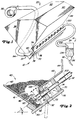
- Figure 1 shows part of a seeder 10 or a similar machine for introducing seeds into the soil, for.
- B. a precision seeder with a transversely extending main frame.
- a plurality of row sowing units 14 are each provided at a distance from one another over the width of the main frame in order to deposit seeds in the soil in rows parallel to one another.
- a fertilizer device for applying granulated mineral fertilizer could also be provided.
- a container 20 is carried by the main frame and a conveyor system according to the invention, generally designated 32, delivers seed from the container 20 serving as the main or central container to individual remote secondary containers 34 on each of the row sowing units 14.
- a seed metering device 38 doses the delivery of the seed from the second container 34 to a conventional coulter for placement in a furrow, which is formed by a furrow opener of the row sowing unit 14.
- the container 20 contains an upright and transversely extending reservoir 40 to hold an amount of seeds and deliver it in a simple manner through a floor area 41 into the conveyor system 32.
- the container 20 is provided with upright front and rear walls 42 and 44, to which inwardly converging base parts 46 and 48 adjoin in order to feed the seed to the base region 41.
- a cleaning door 50 provided at the lowest point is hooked in at 52 in order to selectively enable or close access to the floor area 41 and thus to the receiving area of the conveyor system 32. Any remaining seed after the sowing process can also be removed through this cleaning door 50.
- the sides of the container 20 are closed by walls 56.
- a ceiling 60 with an inlet flap 62 closes off the upper region of the container 20.
- the flap 62 and the cleaning door 50 are closed, the container 20 is sealed so that it can be pressurized during operation.
- the rear floor portion 48 extends inwardly from the rear wall 44 and terminates substantially in the center of the container 20 and above the opposite front floor portion 46.
- An air manifold 70 that is substantially the width of the The container 20 extends includes a front wall 72 which extends from the front edge of the rear bottom portion 48 and extends downwardly perpendicular thereto.
- the air manifold 70 also has a rear wall 74 that is parallel to the front wall 72.
- a bottom 76 closes off the lower region of the air distributor 70, while the rear bottom part 48 forms the upper boundary of the air distributor 70, so that it finally has a substantially rectangular cross section, as shown.
- the air distributor 70 is closed on its sides by end walls 78, an air inlet 80 is attached to one of the end walls 78.
- An air supply line 84 is connected to the air inlet 80 and is connected at the other end to an outlet of a constant pressure blower 86 which conveys compressed air into the air distributor 70.
- a plurality of conveying air outlets 90 are spaced apart in the transverse direction along the length of the front wall 72 of the air manifold 70.
- the conveying air outlets 90 are straight tube lengths of a line with a circular cross section and end pieces 92 which extend into the lower region of the seed quantity within the container 20.
- the inner, i.e. H. in Figure 2 right ends of the delivery air exits 90 end flush with the inner, ie. H. surface of the front wall 72 located in the air distributor 70.
- a separate conveying air outlet 90 is preferably provided for each row sowing unit 14.
- a line 100 e.g. B. a tube or a hose for the seed extends through the rear wall 74 of the air distributor 70 into the conveying air outlet 90.
- This line 100 also has a circular cross section with a diameter which is smaller than the inner diameter of a conveying air outlet 90.
- the central axis of the area of the line 100 extending into the air distributor 70 extends at an angle of approximately 20 to 25 degrees to the horizontal.
- the line 100 can in principle be formed in one piece and open directly into the container 20 and / or the second container 34.
- the line 100 can also be advantageous to partially form the line 100 from a flexible and transparent hose and to make the connections of the line 100 to the container 20 and the second container 34 via an end piece 102 or a discharge end 106, as provided in this exemplary embodiment is.
- the end piece 102 of the line 100 has its free end edge is at a distance - d - from the corresponding end edge of the end piece 92 of the conveying air outlet 90 and is offset from this inwards, ie towards the air distributor 70, the distance - d - being within a range of approximately 12.7 mm to 76.2 mm is adjustable in order to be able to change the discharge rate of the seed.
- the line 100 is slidably received in the rear wall 74 of the air distributor 70, so that the distance - d - can be adjusted by moving the line 100 or its end piece 102 in its longitudinal direction.
- the conduit 100 extends rearward and upward from the rear wall 74 of the air manifold 70 and extends to a discharge end 106 (see FIG. 1) in the secondary container 34 to form a self-throttling device, which is hereinafter described in FIG individual is described.
- a dome-shaped structure 110 of air and seed (see FIG. 2) forms within the amount of seed at the end piece 92 of the conveying air outlet 90.
- the air flowing through the dome-shaped environment 110 is discharged again through the line 100, in one direction , which is opposite to the input direction of the air in this embodiment. This flowing air sweeps seed from the dome-shaped structure 110 into the end piece 102 of the line 100.
- the seed grains conveyed into the line 100 are carried to the discharge end 106 by means of the air flowing out of the dome-shaped structure 110.
- the angle alpha that the longitudinal central axis of the line 100 makes with respect to the horizontal and the degree of immersion of the end piece 102 into the conveying air outlet 90 help prevent seed from building up within the conduit 100, which could cause a delay or an obstacle in the build up of the seed transport when the blower 86 is started up, so that there is no blockage.
- the angle alpha of line 100 in the seed is preferably 35 degrees with respect to the horizontal; however, it can be changed to change the seed entry rate and optimize performance for lines 100 of different sizes. A steeper angle decreases the seed discharge rate, while a flatter angle increases it. Below 20 to 25 degrees, the line 100 can clog with seeds and become ineffective with regard to the transport of seeds to the second container 34. Increasing the distance - d - between the ends of end pieces 92 and 102 increases the discharge rate, while decreasing the distance - d- decreases it. With the dimensions of the lines 100 mentioned below, there will be no transport of seeds at a distance of more than 76.2 mm (3 inches). At a distance below 12.7 mm (1/2 inch), line 100 will clog.
- the discharge rate of seeds can also be changed by changing the air pressure and the size, in particular the cross section, of the line 100. A change in the height of line 100 will also change the discharge rate of the seed.
- the separation, ie the distance between the outer surface of the end piece 102 and the inner surface of the conveying air outlet 90 is preferably kept relatively small in relation to the size of the individual seeds that seed cannot migrate back into the air distributor 70 between said surfaces during transport.
- the use of tubes with inner diameters of 25.4 mm (1 inch) and 40.38 mm (1.59 inch) for the line 100 and the conveying air outlet 90 ensures uniform openings for the air inlet and air outlet and prevents maize , Soybeans and other seeds of the same size get into the air distributor 70.
- Each secondary container 34 has side walls 134 and a bottom area 136 that opens toward the metering device 38.
- the discharge end 106 of the conduit 100 extends through the upper region of the side walls 134 and is arranged in the secondary container 34 such that it extends near a side wall 134 and opens downwards.
- air movement through the discharge end 106 is restricted.
- the discharge end 106 is closed to such an extent (see FIG. 1) that the seed can no longer be conveyed through the line 100 and thus the seed supply is cut off.
- the obstruction disappears again and the air flow increases to a sufficient extent so that seed removal can begin again.
- the transport of the seed into the second container 34 continues until the seed has reached the predetermined level again.
Landscapes
- Life Sciences & Earth Sciences (AREA)
- Soil Sciences (AREA)
- Environmental Sciences (AREA)
- Engineering & Computer Science (AREA)
- Mechanical Engineering (AREA)
- Sowing (AREA)
Claims (20)
- Système d'entraînement (32) pour un matériau granulaire, notamment pour un semoir (10) servant à épandre une semence, comportant un récipient (20) pour le matériau, au moins une unité de semage en lignes (14), au moins une canalisation (100) qui, à une extrémité, débouche dans le récipient (20) pour recevoir le matériau directement ou par l'intermédiaire d'une pièce d'extrémité (102), et délivre, à son autre extrémité, le matériau à l'unité de semage en lignes (14), et un ventilateur (86) qui met en pression le récipient (20), par l'intermédiaire d'une sortie (90) pour l'air d'entraînement, caractérisé en ce que la sortie (90) pour l'air d'entraînement et la canalisation (100) ou la pièce d'extrémité (102) sont disposées de telle sorte que leurs embouchures, qui sont tournées l'une vers l'autre, sont voisines et que l'air d'entraînement sortant par la sortie (92) de l'air d'entraînement est projeté dans une direction à l'intérieur de le matériau et est dirigé dans une autre direction vers la canalisation (100).
- Système d'entraînement selon la revendication 1, caractérisé en ce que la canalisation (100) ou la pièce d'extrémité (102) est disposée coaxialement à et à l'intérieur de la sortie (90) pour l'air d'entraînement et à distance de cette dernière.
- Système d'entraînement selon la revendication 1 ou 2, caractérisé en ce que l'axe médian longitudinal de la canalisation (100) ou de la pièce d'extrémité (102) et de la sortie (90) pour l'air d'entraînement fait un angle notamment de plus de 20 degrés par rapport à l'horizontale.
- Système d'entraînement selon la revendication 3, caractérisé en ce que l'angle est égal à environ 35 degrés.
- Système d'entraînement selon une ou plusieurs des revendications précédentes, caractérisé en ce que la canalisation (100) ou la pièce d'extrémité (102) se termine à l'intérieur de la sortie (90) pour l'air d'entraînement en avant de la sortie (90) pour l'air d'entraînement.
- Système d'entraînement selon une ou plusieurs des revendications précédentes, caractérisé en ce que l'inclinaison de l'axe médian longitudinal et/ou la distance, côté extrémité, entre la sortie (90) pour l'air d'entraînement et la canalisation (100) ou la pièce d'extrémité (102) est variable.
- Système d'entraînement selon une ou plusieurs des revendications précédentes, caractérisé en ce que la canalisation (100) ou la pièce d'extrémité (102) et la sortie (90) pour l'air d'entraînement ont une section transversale circulaire.
- Système d'entraînement selon une ou plusieurs des revendications précédentes, caractérisé en ce que pour plusieurs unités de semis en lignes (14) il est prévu plusieurs sorties (90) pour l'air d'entraînement et plusieurs canalisations (100) ou pièces d'extrémité (102), qui sont montées dans un distributeur d'air commun (70).
- Système d'entraînement selon la revendication 8, caractérisé en ce que le distributeur d'air (70) est entouré notamment par une paroi avant et une paroi arrière (72,74), la sortie (90) pour l'air d'entraînement traversant, avec la canalisation (100) ou sa pièce d'extrémité (102), une ouverture aménagée dans la paroi avant, et la canalisation (100) ou la pièce d'extrémité (102) traversant une ouverture ménagée dans la paroi arrière (74), coaxialement à l'axe médian longitudinal commun.
- Système d'entraînement selon une ou plusieurs des revendications précédentes, caractérisé en ce que la canalisation (100) débouche, par son autre extrémité, dans un second récipient (34), d'où le matériau est délivré en direction du sol au moyen d'un dispositif de dosage (38).
- Système d'entraînement selon la revendication 10, caractérisé en ce que la canalisation (100) est raccordée au second récipient (34) au moyen d'une extrémité de sortie (106), dont le bord côté sortie est disposé dans le second récipient (34) à hauteur d'un niveau de remplissage prédéterminé.
- Système d'entraînement selon l'une ou plusieurs des revendications précédentes, caractérisé en ce qu'une porte (50) pour le nettoyage est prévue dans le récipient (20) au-dessous de la sortie (90) pour l'air d'entraînement.
- Procédé pour l'épandage pneumatique d'une matière, notamment d'une semence, d'un récipient (20) placé sous pression et comportant une sortie (90) pour l'air d'entraînement, qui débouche dans ce récipient, et une canalisation (100) ou une pièce d'extrémité (102) de la canalisation (100) pour retirer la matière, caractérisé en ce que de l'air sous pression est injecté au moyen de l'entrée (90) pour l'air d'entraînement, qui est voisine de la sortie pour l'air d'entraînement, dans la matière de telle sorte qu'on obtient un enveloppement, en forme de coupole, avec des particules de matière flottantes et que l'air contenant la matière est évacué par l'intermédiaire de la canalisation (100) ou de sa pièce d'extrémité (102) dans une direction différente de la direction d'entrée.
- Procédé selon la revendication 13, caractérisé en ce que l'air sort dans une direction opposée à la direction d'entrée.
- Procédé selon la revendication 13 ou 14, caractérisé en ce que la canalisation (100) débouche dans un second récipient (34), dans lequel la matière est stockée temporairement avant son épandage sur le sol.
- Procédé selon la revendication 15, caractérisé en ce que la canalisation (100) ou une extrémité de sortie (106), qui forme la terminaison de cette canalisation, se termine à une hauteur de remplissage prédéterminée dans le second récipient (34) est ouverte vers le bas.
- Procédé selon une ou plusieurs des revendications précédentes 13-16, caractérisé en ce que l'air est injecté dans la matière située dans le récipient (20), en traversant un espace de préférence annulaire présent entre la sortie (90) pour l'air d'entraînement et la canalisation (100) ou sa pièce d'extrémité (102).
- Procédé selon une ou plusieurs des revendications précédentes, 13-16, caractérisé en ce que la canalisation (100) ou sa pièce d'extrémité (102) est disposée concentriquement dans la sortie (90) pour l'air d'entraînement et leurs extrémités sont séparées par une distance de préférence variable.
- Système d'entraînement ou procédé selon une ou plusieurs des revendications précédentes, caractérisé par un rapport, obtenu à partir des dimensions indiquées ci-après, pour la formation de la distance entre la sortie (90) pour l'air d'entraînement et la canalisation (100) ou sa pièce terminale (102) :diamètre intérieur de la sortie (90) pour l'air d'entraînement = 39,62 mmdiamètre extérieur de la canalisation (100) ou de sa pièce d'extrémité (102) = 25,4 mmdistance des bords d'extrémité de la sortie (90) pour l'air d'entraînement et de la canalisation (100) ou de sa pièce d'extrémité (102) = 12,7 mm à 76,2 mm.
- Système d'entraînement ou procédé selon une ou plusieurs des revendications précédentes, caractérisé par une disposition relative de la sortie (90) pour l'air d'entraînement et de la canalisation (100) ou de la pièce d'extrémité (102) de telle sorte qu'on peut obtenir une limitation du déplacement de la matière et de son flux volumique dans la canalisation (100).
Applications Claiming Priority (2)
| Application Number | Priority Date | Filing Date | Title |
|---|---|---|---|
| US07/701,939 US5161473A (en) | 1991-05-17 | 1991-05-17 | Seed distribution system and method for a seeding implement |
| US701939 | 1996-08-23 |
Publications (2)
| Publication Number | Publication Date |
|---|---|
| EP0513582A1 EP0513582A1 (fr) | 1992-11-19 |
| EP0513582B1 true EP0513582B1 (fr) | 1997-07-02 |
Family
ID=24819289
Family Applications (1)
| Application Number | Title | Priority Date | Filing Date |
|---|---|---|---|
| EP92107086A Expired - Lifetime EP0513582B1 (fr) | 1991-05-17 | 1992-04-25 | Système et méthode de transport du matériel granulaire |
Country Status (8)
| Country | Link |
|---|---|
| US (1) | US5161473A (fr) |
| EP (1) | EP0513582B1 (fr) |
| AU (1) | AU644284B2 (fr) |
| BR (1) | BR9201797A (fr) |
| CA (1) | CA2065545C (fr) |
| DE (1) | DE59208654D1 (fr) |
| MX (1) | MX9202297A (fr) |
| ZA (1) | ZA923558B (fr) |
Cited By (1)
| Publication number | Priority date | Publication date | Assignee | Title |
|---|---|---|---|---|
| EP2966965B1 (fr) | 2013-03-15 | 2018-05-09 | AGCO-Amity JV, LLC | Appareil agricole avec système de distribution des particules |
Families Citing this family (77)
| Publication number | Priority date | Publication date | Assignee | Title |
|---|---|---|---|---|
| US5332133A (en) * | 1991-11-01 | 1994-07-26 | Nisshin Flour Milling Co., Ltd. | Powder supplying apparatus and powder spraying apparatus |
| US5396851A (en) * | 1993-03-08 | 1995-03-14 | Beaujot; Norbert F. | Dual material dispensing assembly |
| US5379706A (en) * | 1993-04-07 | 1995-01-10 | Agco Corporation | Seed distribution system for planters and drills |
| AU5752594A (en) * | 1993-04-20 | 1994-11-03 | Deere & Company | Air separation tube for a pneumatic delivery system |
| US5485797A (en) * | 1994-04-29 | 1996-01-23 | Deere & Company | Trailing cart for agricultural toolbar |
| FR2730713B1 (fr) * | 1995-02-17 | 1997-06-13 | Nodet Gougis | Dispositif d'alimentation pneumatique en produits granulaires |
| US5655468A (en) * | 1995-05-17 | 1997-08-12 | Case Corporation | Delivery system for an agricultural implement |
| US5740746A (en) * | 1995-08-11 | 1998-04-21 | Case Corporation | Seed material dispensing system for an agricultural planter |
| US6109193A (en) | 1995-12-29 | 2000-08-29 | Case Corporation | Seed planter apparatus and method |
| US6564730B2 (en) | 1995-12-29 | 2003-05-20 | Case Corporation | Seed planter apparatus and method |
| CA2169008C (fr) * | 1996-02-07 | 2006-10-03 | Russell J. Memory | Appareil d'enduction de granules |
| US5628262A (en) * | 1996-06-03 | 1997-05-13 | Nelson; John A. | Interseeding apparatus and method |
| US5947040A (en) * | 1997-08-18 | 1999-09-07 | Deere & Company | Tank pressurization system for air seeder |
| US5915312A (en) * | 1997-08-29 | 1999-06-29 | Case Corporation | Pneumatic seed delivery system |
| US6078635A (en) * | 1998-02-05 | 2000-06-20 | Dubois; Jerry | Seed or particle-counting device |
| US6044779A (en) * | 1998-04-15 | 2000-04-04 | Case Corporation | Multiple drop seed disc |
| US6047652A (en) * | 1998-05-12 | 2000-04-11 | Case Corporation | Seed planter distribution system |
| DE69912678T2 (de) * | 1998-05-22 | 2004-04-15 | Flexi-Coil Ltd., Saskatoon | Regulierung der Gebläseluft in eine pneumatische Drillmaschine |
| US6298797B1 (en) * | 1998-11-05 | 2001-10-09 | Flexi-Coil Ltd. | Nurse inductor apparatus for air seeders |
| US6192813B1 (en) | 1999-05-21 | 2001-02-27 | Flexi-Coil Ltd. | Apparatus for controlling the flow rate of an air seeder |
| US6113003A (en) * | 1999-09-21 | 2000-09-05 | Chapin Manufacturing, Inc. | Compressed air duster with rotatable agitator |
| LU90639B1 (de) * | 2000-09-18 | 2002-03-19 | Wurth Paul Sa | Vorrichtung zum Einleiten von schwer fliessendem Schuettgut in eine Foerderleitung |
| US6634678B2 (en) | 2001-03-20 | 2003-10-21 | Deere & Co. | Seed conduit detachable coupler having a seed cut off |
| US6782835B2 (en) | 2002-03-21 | 2004-08-31 | Case Corporation | Bulk fill delivery recirculation system |
| US6772702B2 (en) | 2002-03-21 | 2004-08-10 | Case Corporation | Lockdown and support structure for agricultural particulate tank |
| US6668738B2 (en) | 2002-03-21 | 2003-12-30 | Case, Llc | Bulk fill delivery venturi system |
| US6675728B2 (en) | 2002-03-21 | 2004-01-13 | Case, Llc | Vented mini-hopper for bulk feed particle delivery system |
| US6725788B2 (en) | 2002-03-26 | 2004-04-27 | Deere & Company | Pneumatic coupler for an agricultural seeding machine |
| US6672229B2 (en) | 2002-05-02 | 2004-01-06 | Case, Llc | Lockdown structure for agricultural particulate tank |
| US6935254B2 (en) * | 2002-08-08 | 2005-08-30 | Deere & Company | Split seed hoppers for seed on demand seeding machine |
| US6688244B1 (en) | 2002-08-08 | 2004-02-10 | Deere & Company | Product on demand delivery system |
| US6609468B1 (en) | 2002-08-08 | 2003-08-26 | Deere & Company | Product on demand delivery system having an agitator assembly |
| AU2003249870A1 (en) * | 2002-08-08 | 2004-03-11 | Deere And Company | Seeding machine |
| US6845724B2 (en) * | 2002-10-29 | 2005-01-25 | Cnh Canada, Ltd. | Dual capability nurse distribution system |
| WO2005003002A1 (fr) * | 2003-07-08 | 2005-01-13 | Asahi Seiki Co., Ltd. | Dispositif d'alimentation de parties minces |
| US6935255B2 (en) | 2003-08-08 | 2005-08-30 | Deere & Company | Auxiliary seed hopper having a removable screen |
| US7140310B2 (en) * | 2003-11-18 | 2006-11-28 | Cnh Canada, Ltd. | System and method for distributing multiple materials from an agricultural vehicle |
| US7093547B2 (en) * | 2004-02-05 | 2006-08-22 | Cnh Canada, Ltd. | Opposed inductor improvements |
| US7025010B2 (en) * | 2004-04-21 | 2006-04-11 | Deere & Company | Flow splitter arrangement for series fed product application units |
| US7213525B2 (en) * | 2004-05-05 | 2007-05-08 | Deere & Company | Nozzle assembly for product-on-demand delivery system |
| US7156029B2 (en) | 2004-05-27 | 2007-01-02 | Cnh America Llc | Collapsible grain chute |
| US7418908B2 (en) * | 2005-04-28 | 2008-09-02 | Deere & Company | Seed hopper and routing structure for varying material delivery to row units |
| JP4617244B2 (ja) * | 2005-11-08 | 2011-01-19 | 富士通株式会社 | 部品供給装置及び部品供給方法 |
| US7779770B2 (en) | 2007-04-30 | 2010-08-24 | Precision Planting, Inc. | Method of retrofitting a pneumatic on-demand seed delivery system and an improved pneumatic on-demand seed delivery system |
| PL3327026T3 (pl) * | 2007-07-09 | 2020-02-28 | Genentech, Inc. | Zapobieganie redukcji wiązań disiarczkowych podczas rekombinacyjnego wytwarzania polipeptydów |
| US7640877B1 (en) | 2008-11-14 | 2010-01-05 | Cnh Canada, Ltd. | Dense phase distribution branch |
| US7743719B2 (en) * | 2008-11-14 | 2010-06-29 | Cnh Canada, Ltd. | Sectional distribution of granular product |
| US7806061B2 (en) * | 2008-11-14 | 2010-10-05 | Cnh Canada, Ltd. | Agricultural implement with dense phase product dispensing and purging |
| US8342373B2 (en) * | 2008-11-14 | 2013-01-01 | Cnh Canada, Ltd. | Valve and method for dense phase flow control |
| US7779769B2 (en) * | 2008-11-14 | 2010-08-24 | Cnh Canada, Ltd. | Agricultural implement with dense phase product flow from a primary container |
| US7789103B2 (en) * | 2008-11-14 | 2010-09-07 | Cnh Canada, Ltd. | Dense phase induction system and method |
| US7798078B2 (en) * | 2008-11-14 | 2010-09-21 | Cnh Canada, Ltd. | Granular containment assembly and method |
| US7798079B2 (en) * | 2008-11-14 | 2010-09-21 | Cnh Canada, Ltd. | Pressure supply assembly for an agricultural implement with dense phase product flow |
| US7752984B2 (en) * | 2008-11-14 | 2010-07-13 | Cnh Canada, Ltd. | Device and method for dense phase transport of seed |
| US7966954B2 (en) * | 2009-06-11 | 2011-06-28 | Cnh America Llc | Air/product flow splitting apparatus for use with product distribution system of an agricultural seeding machine |
| US7938072B2 (en) * | 2009-07-01 | 2011-05-10 | Kinze Manufacturing, Inc. | Air pressure dissipator for air seed delivery system |
| US9302857B2 (en) * | 2012-04-25 | 2016-04-05 | Nordson Corporation | Pneumatic solids transfer pump |
| SE536523C2 (sv) | 2012-05-31 | 2014-01-28 | Vaederstad Verken Ab | Avskiljare, doseringsanordning, lantbruksredskap samt förfarande för avskiljning av granulärt material |
| SE538290C2 (sv) | 2012-05-31 | 2016-04-26 | Vaederstad Holding Ab | Lantbruksredskap och förfarande för matning av granulärt material |
| US9215840B2 (en) | 2013-01-09 | 2015-12-22 | Cnh Industrial Canada, Ltd. | Seed inductor for an agricultural implement having an air bypass channel |
| US9192093B2 (en) | 2013-01-09 | 2015-11-24 | Cnh Industrial Canada, Ltd. | Seed inductor box for an agricultural implement having a fluidization chamber |
| US9439344B2 (en) * | 2013-01-09 | 2016-09-13 | Cnh Industrial Canada, Ltd. | Mirrored inductor segment pairs of an inductor box of an agricultural implement |
| US9265190B2 (en) | 2013-01-09 | 2016-02-23 | Cnh Industrial America Llc | Seed inductor box for an agricultural implement having multiple air paths |
| US9215841B2 (en) * | 2013-01-09 | 2015-12-22 | Cnh Industrial America Llc | Seed inductor for an agricultural implement having an adjustable air bypass |
| US9688487B2 (en) * | 2013-03-28 | 2017-06-27 | Nordson Corporation | Adhesive bin and method of storing and moving adhesive particulate to an adhesive melter |
| US9725254B2 (en) | 2014-08-21 | 2017-08-08 | Cnh Industrial Canada, Ltd. | Configurations of inlet and outlets of air filled auxiliary tank of air seeders |
| US9950876B2 (en) * | 2014-09-26 | 2018-04-24 | Cnh Industrial Canada, Ltd. | Downward elbow with cyclonic effect and product overflow capability |
| US9591800B2 (en) | 2014-11-19 | 2017-03-14 | Cnh Industrial Canada, Ltd. | Agricultural implement metering system and method |
| DE102015110009A1 (de) | 2015-06-23 | 2016-12-29 | Amazonen-Werke H. Dreyer Gmbh & Co. Kg | Vorrichtung zum Fördern von auf einer landwirtschaftlichen Fläche auszubringendem granularem Material mit verbesserter Luftströmung |
| DE102015110011A1 (de) | 2015-06-23 | 2016-12-29 | Amazonen-Werke H. Dreyer Gmbh & Co. Kg | Vorrichtung zum Fördern von auf einer landwirtschaftlichen Fläche auszubringendem granularem Material mit verbesserter pneumatischer Förderung |
| DE102016125336A1 (de) * | 2016-12-22 | 2018-06-28 | Amazonen-Werke H. Dreyer Gmbh & Co. Kg | Landwirtschaftliche Kombination und Verfahren zum Betreiben der Kombination |
| US10296017B2 (en) | 2017-03-08 | 2019-05-21 | Cnh Industrial America Llc | Pre-metering system for feeding different types of seed into a seed meter |
| US11013167B2 (en) | 2017-12-14 | 2021-05-25 | Cnh Industrial America Llc | Bulk product tank for an agricultural implement |
| AR112607A1 (es) | 2018-07-10 | 2019-11-20 | Talleres Metalurgicos Crucianelli S A | Dispositivo de entrega de partículas sólidas bajo demanda, aplicada a una máquina agrícola |
| US11877529B2 (en) | 2019-02-01 | 2024-01-23 | Cnh Industrial Canada, Ltd. | Deflector of an agricultural agitation system |
| US11484853B2 (en) | 2019-02-01 | 2022-11-01 | Cnh Industrial Canada, Ltd. | Deflector of an agricultural agitation system |
| US20220183219A1 (en) * | 2020-12-15 | 2022-06-16 | Cnh Industrial Canada, Ltd. | Seed opener having a singulation tube incorporated within |
Family Cites Families (23)
| Publication number | Priority date | Publication date | Assignee | Title |
|---|---|---|---|---|
| US168029A (en) * | 1875-09-21 | Improvement in grain-elevators | ||
| US2525718A (en) * | 1945-06-21 | 1950-10-10 | Parker Wallace James | Device for sowing seeds |
| US2676852A (en) * | 1950-07-20 | 1954-04-27 | Houdry Process Corp | Apparatus for elevating granular material |
| US2758564A (en) * | 1951-05-15 | 1956-08-14 | Ralph B Randall | Apparatus for coating with dry dust |
| US2955877A (en) * | 1959-01-05 | 1960-10-11 | Ecal Francois | Pneumatic device for the transport and scattering of powdered products |
| US3189230A (en) * | 1962-03-20 | 1965-06-15 | Robert V Gillespie | Seeding device |
| FR1361034A (fr) * | 1963-06-21 | 1964-05-15 | Engelbrecht & Lemmerbrock | Perfectionnements apportés aux dispositifs de vidange pneumatiques des fosses à céréales ou analogues |
| US3387746A (en) * | 1966-11-28 | 1968-06-11 | Robert F Ashley | Selective seed planter |
| AU426984B2 (en) * | 1967-01-03 | 1972-08-09 | Harold Goulter Victor | Improved seed sower or other distributing device |
| FR1558490A (fr) * | 1967-12-27 | 1969-02-28 | ||
| US3804036A (en) * | 1972-10-05 | 1974-04-16 | E Seifert | Air induction apparatus for seed drill tube |
| US4060181A (en) * | 1975-07-03 | 1977-11-29 | Nodet-Gougis (Societe De Droit Francais) | Method and apparatus for controlling the transfer of particulate material |
| US4286530A (en) * | 1979-07-26 | 1981-09-01 | Conley Richard L | Multiple row seed planter with common seed storage |
| FR2479644A1 (fr) * | 1980-04-04 | 1981-10-09 | Nodet Gougis | Semoir a ejecteur pneumatique de graines, notamment pour cultures legumieres |
| US4298018A (en) * | 1980-07-29 | 1981-11-03 | Chemed Corporation | Pumping process |
| US4503786A (en) * | 1980-12-24 | 1985-03-12 | Tautfest Rexford L | Grain drill with sealed bin air-powered distribution |
| US4474327A (en) * | 1981-09-11 | 1984-10-02 | Allegretti & Company | Fertilizer spreader |
| US4473016A (en) * | 1982-09-23 | 1984-09-25 | Concord, Inc. | Particulate feeder system |
| US4503708A (en) * | 1983-02-07 | 1985-03-12 | Board Of Trustees Of The Leland Stanford Junior University | Reflection acoustic microscope for precision differential phase imaging |
| US4562968A (en) * | 1984-03-19 | 1986-01-07 | Dry Sprayer, Inc. | Pneumatic spreader |
| US4733824A (en) * | 1984-07-27 | 1988-03-29 | Frederick Alexander | Particulate material distributor, having a tensioned flexible cover for clean-out aperture below hopper |
| GB8514287D0 (en) * | 1985-06-06 | 1985-07-10 | Alcan Int Ltd | Feeding particulate material |
| AU647168B2 (en) * | 1990-08-27 | 1994-03-17 | Michael Crosbie Kendall | Air seeder apparatus |
-
1991
- 1991-05-17 US US07/701,939 patent/US5161473A/en not_active Expired - Lifetime
-
1992
- 1992-04-07 CA CA002065545A patent/CA2065545C/fr not_active Expired - Fee Related
- 1992-04-25 EP EP92107086A patent/EP0513582B1/fr not_active Expired - Lifetime
- 1992-04-25 DE DE59208654T patent/DE59208654D1/de not_active Expired - Fee Related
- 1992-04-29 AU AU15285/92A patent/AU644284B2/en not_active Ceased
- 1992-05-13 BR BR929201797A patent/BR9201797A/pt not_active IP Right Cessation
- 1992-05-15 MX MX9202297A patent/MX9202297A/es not_active IP Right Cessation
- 1992-05-15 ZA ZA923558A patent/ZA923558B/xx unknown
Cited By (1)
| Publication number | Priority date | Publication date | Assignee | Title |
|---|---|---|---|---|
| EP2966965B1 (fr) | 2013-03-15 | 2018-05-09 | AGCO-Amity JV, LLC | Appareil agricole avec système de distribution des particules |
Also Published As
| Publication number | Publication date |
|---|---|
| AU1528592A (en) | 1992-11-19 |
| CA2065545C (fr) | 1995-04-18 |
| EP0513582A1 (fr) | 1992-11-19 |
| AU644284B2 (en) | 1993-12-02 |
| MX9202297A (es) | 1992-11-01 |
| DE59208654D1 (de) | 1997-08-07 |
| ZA923558B (en) | 1993-05-15 |
| US5161473A (en) | 1992-11-10 |
| BR9201797A (pt) | 1993-01-05 |
Similar Documents
| Publication | Publication Date | Title |
|---|---|---|
| EP0513582B1 (fr) | Système et méthode de transport du matériel granulaire | |
| EP3026998B1 (fr) | Procédé et dispositif de dosage de matériel granulaire | |
| EP3372065B1 (fr) | Tour de distribution d'une machine agricole, machine agricole et procédé de fonctionnement d'une telle machine agricole | |
| DE69921938T2 (de) | Adapter für Behälter in pneumatischen Drillmaschinen | |
| EP0799560B1 (fr) | Conduite pour l'air de sortie d'un distributeur pneumatique | |
| DE2629278C3 (de) | Verfahren und Vorrichtung zum Regeln des Füllstandes in mindestens einem Verteilerbehälter | |
| EP0620963A1 (fr) | Appareil de transport de graines à semer | |
| EP0732044B1 (fr) | Conduit pour machine agricole | |
| WO2016134397A1 (fr) | Dispositif de refoulement pneumatique et installation de dosage ainsi qu'installation de sablage comprenant une pompe à jet de produit coulant | |
| DE102010002200A1 (de) | Kalibriervorrichtung | |
| DE2122858C3 (de) | Einrichtung zum pneumatischen Bilden und Fördern von durch Druckluftpolster voneinander getrennten Materialpfropfen in einer Leitung | |
| DE2821517C2 (de) | Pneumatische Förderanlage für pulverförmiges Gut | |
| EP2805596A1 (fr) | Semoir | |
| DE4430155C2 (de) | Sämaschine | |
| DE102011113577A1 (de) | Pneumatische Verteilmaschine | |
| EP3704923B1 (fr) | Dispositif pour un semoir agricole, procédé de séparation des semences dans un dispositif pour un semoir agricole ainsi que semoir | |
| EP3108733B1 (fr) | Dispositif de transport a flux d'air ameliore de materiau granulaire a epandre sur une surface agricole | |
| EP3689121B1 (fr) | Module de scie, jeu de mise à niveau pour le module de scie et semoir monograine pourvu de modules de scie | |
| DE4219616A1 (de) | Verfahren zur pneumatischen Förderung von Schüttgut und Vorrichtung dafür | |
| DE102019102256B3 (de) | Materialeinleitschleuse für eine Verteilmaschine und Verteilmaschine | |
| DE3613464C2 (de) | Vorrichtung zum Transportieren von staubförmigem oder körnigem Gut - Baustoffmischungen - (Fördergut) zur Verwendung im Untertagebergbau | |
| DE3515362A1 (de) | Vorrichtung zum streuen von schuettfaehigem gut, insbesondere duenger | |
| EP3108734B1 (fr) | Dispositif de transport pneumatique ameliore de materiau granulaire a epandre sur une surface agricole | |
| DE202004002615U1 (de) | Pneumatisch arbeitende Verteilmaschine | |
| DE901878C (de) | Zusatzeinrichtung an pneumatischen Foerderanlagen fuer Muehlen |
Legal Events
| Date | Code | Title | Description |
|---|---|---|---|
| PUAI | Public reference made under article 153(3) epc to a published international application that has entered the european phase |
Free format text: ORIGINAL CODE: 0009012 |
|
| AK | Designated contracting states |
Kind code of ref document: A1 Designated state(s): DE FR IT |
|
| 17P | Request for examination filed |
Effective date: 19930429 |
|
| 17Q | First examination report despatched |
Effective date: 19940719 |
|
| GRAG | Despatch of communication of intention to grant |
Free format text: ORIGINAL CODE: EPIDOS AGRA |
|
| GRAH | Despatch of communication of intention to grant a patent |
Free format text: ORIGINAL CODE: EPIDOS IGRA |
|
| GRAH | Despatch of communication of intention to grant a patent |
Free format text: ORIGINAL CODE: EPIDOS IGRA |
|
| GRAA | (expected) grant |
Free format text: ORIGINAL CODE: 0009210 |
|
| AK | Designated contracting states |
Kind code of ref document: B1 Designated state(s): DE FR IT |
|
| REF | Corresponds to: |
Ref document number: 59208654 Country of ref document: DE Date of ref document: 19970807 |
|
| ET | Fr: translation filed | ||
| ITF | It: translation for a ep patent filed |
Owner name: LENZI & C. |
|
| PLBE | No opposition filed within time limit |
Free format text: ORIGINAL CODE: 0009261 |
|
| STAA | Information on the status of an ep patent application or granted ep patent |
Free format text: STATUS: NO OPPOSITION FILED WITHIN TIME LIMIT |
|
| 26N | No opposition filed | ||
| PGFP | Annual fee paid to national office [announced via postgrant information from national office to epo] |
Ref country code: IT Payment date: 20060430 Year of fee payment: 15 |
|
| PGFP | Annual fee paid to national office [announced via postgrant information from national office to epo] |
Ref country code: DE Payment date: 20080319 Year of fee payment: 17 |
|
| PGFP | Annual fee paid to national office [announced via postgrant information from national office to epo] |
Ref country code: FR Payment date: 20080417 Year of fee payment: 17 |
|
| PG25 | Lapsed in a contracting state [announced via postgrant information from national office to epo] |
Ref country code: IT Free format text: LAPSE BECAUSE OF NON-PAYMENT OF DUE FEES Effective date: 20070425 |
|
| REG | Reference to a national code |
Ref country code: FR Ref legal event code: ST Effective date: 20091231 |
|
| PG25 | Lapsed in a contracting state [announced via postgrant information from national office to epo] |
Ref country code: DE Free format text: LAPSE BECAUSE OF NON-PAYMENT OF DUE FEES Effective date: 20091103 |
|
| PG25 | Lapsed in a contracting state [announced via postgrant information from national office to epo] |
Ref country code: FR Free format text: LAPSE BECAUSE OF NON-PAYMENT OF DUE FEES Effective date: 20091222 |