EP0513582B1 - System and method for conveying granular material - Google Patents
System and method for conveying granular material Download PDFInfo
- Publication number
- EP0513582B1 EP0513582B1 EP92107086A EP92107086A EP0513582B1 EP 0513582 B1 EP0513582 B1 EP 0513582B1 EP 92107086 A EP92107086 A EP 92107086A EP 92107086 A EP92107086 A EP 92107086A EP 0513582 B1 EP0513582 B1 EP 0513582B1
- Authority
- EP
- European Patent Office
- Prior art keywords
- pipeline
- conveyor
- air
- end piece
- container
- Prior art date
- Legal status (The legal status is an assumption and is not a legal conclusion. Google has not performed a legal analysis and makes no representation as to the accuracy of the status listed.)
- Expired - Lifetime
Links
Images
Classifications
-
- A—HUMAN NECESSITIES
- A01—AGRICULTURE; FORESTRY; ANIMAL HUSBANDRY; HUNTING; TRAPPING; FISHING
- A01C—PLANTING; SOWING; FERTILISING
- A01C7/00—Sowing
- A01C7/08—Broadcast seeders; Seeders depositing seeds in rows
- A01C7/081—Seeders depositing seeds in rows using pneumatic means
-
- B—PERFORMING OPERATIONS; TRANSPORTING
- B65—CONVEYING; PACKING; STORING; HANDLING THIN OR FILAMENTARY MATERIAL
- B65G—TRANSPORT OR STORAGE DEVICES, e.g. CONVEYORS FOR LOADING OR TIPPING, SHOP CONVEYOR SYSTEMS OR PNEUMATIC TUBE CONVEYORS
- B65G53/00—Conveying materials in bulk through troughs, pipes or tubes by floating the materials or by flow of gas, liquid or foam
- B65G53/34—Details
- B65G53/40—Feeding or discharging devices
- B65G53/42—Nozzles
-
- Y—GENERAL TAGGING OF NEW TECHNOLOGICAL DEVELOPMENTS; GENERAL TAGGING OF CROSS-SECTIONAL TECHNOLOGIES SPANNING OVER SEVERAL SECTIONS OF THE IPC; TECHNICAL SUBJECTS COVERED BY FORMER USPC CROSS-REFERENCE ART COLLECTIONS [XRACs] AND DIGESTS
- Y10—TECHNICAL SUBJECTS COVERED BY FORMER USPC
- Y10S—TECHNICAL SUBJECTS COVERED BY FORMER USPC CROSS-REFERENCE ART COLLECTIONS [XRACs] AND DIGESTS
- Y10S111/00—Planting
- Y10S111/90—Methods of planting seeds and miscellaneous compositions
Definitions
- the invention relates to a conveyor system for granular material, in particular for a seed drill for spreading seeds, with a container for the material, at least one row sowing unit, at least one line which opens at one end for receiving material directly or via an end piece into the container and at the other end Dispenses good to the row sowing unit, and a blower that pressurizes the container via a conveying air outlet, as well as a method for the pneumatic discharge of material, in particular seed, from a container with a conveying air outlet opening into this and a line or an end piece of the Line for the removal of the good.
- US-A-3,548,765 discloses a seeder with a main container for receiving seed and several secondary containers fed from it with seed, which are placed on independent row sowing units and buffer the seed before metering into a furrow by means of a measuring wheel.
- a sieve is provided on which the seed is stored. Below the sieve there is thus a chamber which is filled with compressed air by a blower, which penetrates the seed through the sieve and puts the airtight container under pressure as a whole.
- a line opens into the main hopper, into which the seeds enter due to the air flow and should therefore be fed to the secondary hopper.
- This seeder is disadvantageous in that a reliable entry of the seed into the line is very much dependent on the nature of the seed, the thickness of the seed mat and the like.
- FR-1.361.034 discloses a discharge device for a pressureless silo with a suction pipe, which according to an illustrated embodiment is accommodated in an air guide pipe and the height of which can be adjusted. As soon as a suction device, not shown, is put into operation, bulk material is removed from the silo through the suction pipe. Compressed air is not supplied.
- the object on which the invention is based is seen in proposing a conveyor system or a method which ensure reliable acceptance of the goods and can be carried out with simple means.
- the inclined arrangement of the line and the conveying air outlet to the horizontal in a region above and preferably at 35 degrees ensures that there is no blockage in the line and that the air flow still entrains the goods, i.e. H. can lift.
- the effect of the air flow on the goods and the risk of the line being blocked by goods can be reduced if the line or its end piece ends within the conveying air outlet before the conveying air outlet, i. H. there is a gap between the two edges.
- An adaptation to the different conditions or types of goods is possible if the aforementioned distance is adjustable.
- a flow loss-free supply of the air into the container through the annular space between the conveying air outlet and the line or the end piece is achieved if this annular space is round instead of polygonal.
- the benefit of the invention becomes all the greater if a plurality of row sowing units are fed by means of the conveyor system according to the invention, whereby part savings can be achieved in that compressed air is not supplied separately to each conveying air outlet, but rather via an air distributor common to all conveying air outlets and accommodating them Container arrives. For this are the conveying air outlets and the lines or end pieces are inserted into the walls of the air distributor in the specified manner.
- the supply of the crop to the row sowing unit does not necessarily mean that it is also deposited directly in the ground; rather, it can also first be placed in a second container, in which it is temporarily stored and removed by means of a metering device.
- an automatic filling limitation which consists in that the line or a discharge end connected to this end, which can have the shape of a tube angle, can end with its lower edge at the level of a desired filling level of the goods. As soon as the filled goods reach this lower, preferably horizontal edge, the air is prevented from exiting and a further supply of goods is interrupted.
- the method according to the invention teaches how the flow processes are to be set up so that the desired conveying effect occurs.
- the reversal of the direction of flow of 180 degrees ensures particularly effective entrainment of the material into the line.
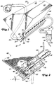
- Figure 1 shows part of a seeder 10 or a similar machine for introducing seeds into the soil, for.
- B. a precision seeder with a transversely extending main frame.
- a plurality of row sowing units 14 are each provided at a distance from one another over the width of the main frame in order to deposit seeds in the soil in rows parallel to one another.
- a fertilizer device for applying granulated mineral fertilizer could also be provided.
- a container 20 is carried by the main frame and a conveyor system according to the invention, generally designated 32, delivers seed from the container 20 serving as the main or central container to individual remote secondary containers 34 on each of the row sowing units 14.
- a seed metering device 38 doses the delivery of the seed from the second container 34 to a conventional coulter for placement in a furrow, which is formed by a furrow opener of the row sowing unit 14.
- the container 20 contains an upright and transversely extending reservoir 40 to hold an amount of seeds and deliver it in a simple manner through a floor area 41 into the conveyor system 32.
- the container 20 is provided with upright front and rear walls 42 and 44, to which inwardly converging base parts 46 and 48 adjoin in order to feed the seed to the base region 41.
- a cleaning door 50 provided at the lowest point is hooked in at 52 in order to selectively enable or close access to the floor area 41 and thus to the receiving area of the conveyor system 32. Any remaining seed after the sowing process can also be removed through this cleaning door 50.
- the sides of the container 20 are closed by walls 56.
- a ceiling 60 with an inlet flap 62 closes off the upper region of the container 20.
- the flap 62 and the cleaning door 50 are closed, the container 20 is sealed so that it can be pressurized during operation.
- the rear floor portion 48 extends inwardly from the rear wall 44 and terminates substantially in the center of the container 20 and above the opposite front floor portion 46.
- An air manifold 70 that is substantially the width of the The container 20 extends includes a front wall 72 which extends from the front edge of the rear bottom portion 48 and extends downwardly perpendicular thereto.
- the air manifold 70 also has a rear wall 74 that is parallel to the front wall 72.
- a bottom 76 closes off the lower region of the air distributor 70, while the rear bottom part 48 forms the upper boundary of the air distributor 70, so that it finally has a substantially rectangular cross section, as shown.
- the air distributor 70 is closed on its sides by end walls 78, an air inlet 80 is attached to one of the end walls 78.
- An air supply line 84 is connected to the air inlet 80 and is connected at the other end to an outlet of a constant pressure blower 86 which conveys compressed air into the air distributor 70.
- a plurality of conveying air outlets 90 are spaced apart in the transverse direction along the length of the front wall 72 of the air manifold 70.
- the conveying air outlets 90 are straight tube lengths of a line with a circular cross section and end pieces 92 which extend into the lower region of the seed quantity within the container 20.
- the inner, i.e. H. in Figure 2 right ends of the delivery air exits 90 end flush with the inner, ie. H. surface of the front wall 72 located in the air distributor 70.
- a separate conveying air outlet 90 is preferably provided for each row sowing unit 14.
- a line 100 e.g. B. a tube or a hose for the seed extends through the rear wall 74 of the air distributor 70 into the conveying air outlet 90.
- This line 100 also has a circular cross section with a diameter which is smaller than the inner diameter of a conveying air outlet 90.
- the central axis of the area of the line 100 extending into the air distributor 70 extends at an angle of approximately 20 to 25 degrees to the horizontal.
- the line 100 can in principle be formed in one piece and open directly into the container 20 and / or the second container 34.
- the line 100 can also be advantageous to partially form the line 100 from a flexible and transparent hose and to make the connections of the line 100 to the container 20 and the second container 34 via an end piece 102 or a discharge end 106, as provided in this exemplary embodiment is.
- the end piece 102 of the line 100 has its free end edge is at a distance - d - from the corresponding end edge of the end piece 92 of the conveying air outlet 90 and is offset from this inwards, ie towards the air distributor 70, the distance - d - being within a range of approximately 12.7 mm to 76.2 mm is adjustable in order to be able to change the discharge rate of the seed.
- the line 100 is slidably received in the rear wall 74 of the air distributor 70, so that the distance - d - can be adjusted by moving the line 100 or its end piece 102 in its longitudinal direction.
- the conduit 100 extends rearward and upward from the rear wall 74 of the air manifold 70 and extends to a discharge end 106 (see FIG. 1) in the secondary container 34 to form a self-throttling device, which is hereinafter described in FIG individual is described.
- a dome-shaped structure 110 of air and seed (see FIG. 2) forms within the amount of seed at the end piece 92 of the conveying air outlet 90.
- the air flowing through the dome-shaped environment 110 is discharged again through the line 100, in one direction , which is opposite to the input direction of the air in this embodiment. This flowing air sweeps seed from the dome-shaped structure 110 into the end piece 102 of the line 100.
- the seed grains conveyed into the line 100 are carried to the discharge end 106 by means of the air flowing out of the dome-shaped structure 110.
- the angle alpha that the longitudinal central axis of the line 100 makes with respect to the horizontal and the degree of immersion of the end piece 102 into the conveying air outlet 90 help prevent seed from building up within the conduit 100, which could cause a delay or an obstacle in the build up of the seed transport when the blower 86 is started up, so that there is no blockage.
- the angle alpha of line 100 in the seed is preferably 35 degrees with respect to the horizontal; however, it can be changed to change the seed entry rate and optimize performance for lines 100 of different sizes. A steeper angle decreases the seed discharge rate, while a flatter angle increases it. Below 20 to 25 degrees, the line 100 can clog with seeds and become ineffective with regard to the transport of seeds to the second container 34. Increasing the distance - d - between the ends of end pieces 92 and 102 increases the discharge rate, while decreasing the distance - d- decreases it. With the dimensions of the lines 100 mentioned below, there will be no transport of seeds at a distance of more than 76.2 mm (3 inches). At a distance below 12.7 mm (1/2 inch), line 100 will clog.
- the discharge rate of seeds can also be changed by changing the air pressure and the size, in particular the cross section, of the line 100. A change in the height of line 100 will also change the discharge rate of the seed.
- the separation, ie the distance between the outer surface of the end piece 102 and the inner surface of the conveying air outlet 90 is preferably kept relatively small in relation to the size of the individual seeds that seed cannot migrate back into the air distributor 70 between said surfaces during transport.
- the use of tubes with inner diameters of 25.4 mm (1 inch) and 40.38 mm (1.59 inch) for the line 100 and the conveying air outlet 90 ensures uniform openings for the air inlet and air outlet and prevents maize , Soybeans and other seeds of the same size get into the air distributor 70.
- Each secondary container 34 has side walls 134 and a bottom area 136 that opens toward the metering device 38.
- the discharge end 106 of the conduit 100 extends through the upper region of the side walls 134 and is arranged in the secondary container 34 such that it extends near a side wall 134 and opens downwards.
- air movement through the discharge end 106 is restricted.
- the discharge end 106 is closed to such an extent (see FIG. 1) that the seed can no longer be conveyed through the line 100 and thus the seed supply is cut off.
- the obstruction disappears again and the air flow increases to a sufficient extent so that seed removal can begin again.
- the transport of the seed into the second container 34 continues until the seed has reached the predetermined level again.
Description
Die Erfindung betrifft ein Fördersystem für körniges Gut, insbesondere für eine Sämaschine zum Ausbringen von Saatgut, mit einem Behälter für das Gut, wenigstens einer Reihensäeinheit, wenigstens einer Leitung, die einenends zur Aufnahme von Gut direkt oder über ein Endstück in den Behälter mündet und anderenends Gut an die Reihensäeinheit abgibt, und einem Gebläse, das über einen Förderluftausgang den Behälter unter Druck setzt, sowie ein Verfahren zum pneumatischen Austragen von Gut, insbesondere von Saatgut, aus einem Behälter mit einem in diesen mündenden Förderluftausgang und einer Leitung bzw. einem Endstück der Leitung zur Entfernung des Guts.The invention relates to a conveyor system for granular material, in particular for a seed drill for spreading seeds, with a container for the material, at least one row sowing unit, at least one line which opens at one end for receiving material directly or via an end piece into the container and at the other end Dispenses good to the row sowing unit, and a blower that pressurizes the container via a conveying air outlet, as well as a method for the pneumatic discharge of material, in particular seed, from a container with a conveying air outlet opening into this and a line or an end piece of the Line for the removal of the good.
Die US-A-3,548,765 offenbart eine Sämaschine mit einem Hauptbehälter zur Aufnahme von Saatgut und mehreren aus diesem mit Saatgut gespeisten Nebenbehältern, die auf voneinander unabhängige Reihensäeinheiten aufgesetzt sind und das Saatgut vor der dosierten Abgabe in eine Furche mittels eines Meßrades zwischenspeichern. Mit Abstand zu dem Boden des Hauptbehälters ist ein Sieb vorgesehen, auf dem das Saatgut lagert. Unterhalb des Siebs ergibt sich somit eine Kammer, die von einem Gebläse mit Druckluft gefüllt wird, die durch das Sieb das Saatgut durchdringt und den luftdichten Behälter insgesamt unter Druck setzt. Oberhalb des Siebs mündet eine Leitung in den Hauptbehälter, in die das Saatgut aufgrund der Luftströmung eintreten und somit dem Nebenbehälter zugeführt werden soll.US-A-3,548,765 discloses a seeder with a main container for receiving seed and several secondary containers fed from it with seed, which are placed on independent row sowing units and buffer the seed before metering into a furrow by means of a measuring wheel. At a distance from the bottom of the main container, a sieve is provided on which the seed is stored. Below the sieve there is thus a chamber which is filled with compressed air by a blower, which penetrates the seed through the sieve and puts the airtight container under pressure as a whole. Above the sieve, a line opens into the main hopper, into which the seeds enter due to the air flow and should therefore be fed to the secondary hopper.
Diese Sämaschine ist insofern nachteilig, als ein zuverlässiger Eintritt des Saatguts in die Leitung sehr stark von der Beschaffenheit des Saatguts, der Dicke der Saatgutmatte und dergleichen abhängig ist.This seeder is disadvantageous in that a reliable entry of the seed into the line is very much dependent on the nature of the seed, the thickness of the seed mat and the like.
Bei einem Fördersystem einer aus der US-A-4,060,181 bekannten Sämaschine wird das Saatgut unter Ausnutzung des Venturi-Effekts ausgetragen, d. h. mittels eines die Richtung nicht ändernden Luftstroms, der in seinem Außenbereich einen Sog aufbaut, der Gut mitreißt.In a conveyor system of a seed drill known from US-A-4,060,181, the seed is discharged using the Venturi effect, i. H. by means of an air flow which does not change direction and which builds up a suction in its outer area, which sweeps the goods along.
Bei diesem Fördersystem ist eine Gutmitnahme bei kompaktem Gut ebenfalls problematisch.With this conveyor system, taking good goods with compact goods is also problematic.
Die Anwendung des Venturi-Effekts zum Austragen von Pulver ist auch für andere Anwendungszwecke z. B. aus der US-A-2,955,877 bekannt.The use of the Venturi effect for the discharge of powder is also for other applications such. B. is known from US-A-2,955,877.
Die FR-1.361.034 offenbart eine Austragsvorrichtung für ein druckloses Silo mit einem Saugrohr, das nach eine dargestellten Ausführungsbeispiel in einem Luftführungsrohr aufgenommen ist und in der Höhe verstellt werden kann. Sobald eine nicht gezeigte Saugvorrichtung in Betrieb gesetzt ist, wird Schüttgut aus dem Silo durch das Saugrohr entnommen. Druckluft wird nicht zugeführt.FR-1.361.034 discloses a discharge device for a pressureless silo with a suction pipe, which according to an illustrated embodiment is accommodated in an air guide pipe and the height of which can be adjusted. As soon as a suction device, not shown, is put into operation, bulk material is removed from the silo through the suction pipe. Compressed air is not supplied.
Die der Erfindung zugrunde liegende Aufgabe wird darin gesehen, ein Fördersystem bzw. ein Verfahren vorzuschlagen, die eine sichere Gutannahme gewährleisten und mit einfachen Mitteln ausführbar sind.The object on which the invention is based is seen in proposing a conveyor system or a method which ensure reliable acceptance of the goods and can be carried out with simple means.
Diese Aufgabe wird erfindungsgemäß durch die Lehre der Patentansprüche 1 bzw. 13 gelöst, wobei in den jeweils weiteren Patentansprüchen Merkmale aufgeführt sind, die die Lösung in vorteilhafter Weise weiterentwickeln.According to the invention, this object is achieved by the teaching of claims 1 and 13, respectively, features being listed in the further claims, which further develop the solution in an advantageous manner.
Auf diese Weise findet im unmittelbaren Bereich der einströmenden Luft eine Wirbel- und Turbulenzenbildung statt, die das Gut lockert und in einem innerhalb des Guts gebildeten kuppelförmigen Bereich umherwirbelt, so daß das Gut von der zu der Leitung ausströmenden Luft ausgetragen werden kann. Anders als im Stand der Technik kommt es nicht auf einen Mitnahmeeffekt aufgrund einer Sogwirkung an, sondern das Gut wird direkt beaufschlagt und in den Luftstrom einbezogen.In this way, eddy and turbulence formation takes place in the immediate area of the inflowing air, which loosens the material and swirls around in a dome-shaped area formed within the material, so that the material can be discharged from the air flowing out to the line. In contrast to the state of the art, it is not a question of a carry-along effect due to a suction effect, but the material is acted upon directly and included in the air flow.
Es wird darauf hingewiesen, daß der Begriff "Luft" nicht beschränkend benutzt ist, sondern daß er für die Gattung "Gas" an sich steht, also auch andere Gase oder Gasgemische erfaßt.It is pointed out that the term "air" is not used restrictively, but that it is used for the genus "Gas" is itself, so other gases or gas mixtures detected.
Eine umfassende Wirbelbildung und die Einleitung der Luft in unmittelbarer Nachbarschaft zu deren Austrittsstelle ist insbesondere dann gegeben, wenn die Leitung bzw. das Endstück koaxial zu und innerhalb des Förderluftausgangs und mit Abstand zu diesem angeordnet ist.Comprehensive vortex formation and the introduction of air in the immediate vicinity of its outlet point are given in particular if the line or the end piece is arranged coaxially with and within the conveying air outlet and at a distance from it.
Die geneigte Anordnung der Leitung und des Förderluftausgangs zu der Horizontalen in einem Bereich oberhalb und vorzugsweise bei 35 Grad stellt sicher, daß es in der Leitung nicht zu einer Verstopfung kommt und der Luftstrom das Gut noch mitnehmen, d. h. anheben kann.The inclined arrangement of the line and the conveying air outlet to the horizontal in a region above and preferably at 35 degrees ensures that there is no blockage in the line and that the air flow still entrains the goods, i.e. H. can lift.
Die Einwirkung des Luftstroms auf das Gut und die Gefahr des Zusetzens der Leitung durch Gut kann verringert werden, wenn die Leitung bzw. deren Endstück innerhalb des Förderluftausgangs vor dem Förderluftausgang endet, d. h. zwischen beiden Kanten ein Abstand bleibt. Eine Anpassung an die verschiedenen Zustände oder Art der Güter ist möglich, wenn der vorgenannte Abstand einstellbar ist.The effect of the air flow on the goods and the risk of the line being blocked by goods can be reduced if the line or its end piece ends within the conveying air outlet before the conveying air outlet, i. H. there is a gap between the two edges. An adaptation to the different conditions or types of goods is possible if the aforementioned distance is adjustable.
Eine strömungsverlustarme Zuführung der Luft in den Behälter durch den Ringraum zwischen dem Förderluftausgang und der Leitung bzw. dem Endstück wird erreicht, wenn dieser Ringraum rund ist, anstatt mehreckig.A flow loss-free supply of the air into the container through the annular space between the conveying air outlet and the line or the end piece is achieved if this annular space is round instead of polygonal.
Der Nutzen der Erfindung wird umso größer, wenn mittels des erfindungsgemäßen Fördersystems eine Vielzahl von Reihensäeinheiten beschickt werden, wobei eine Teileeinsparung dadurch erreicht werden kann, daß nicht jedem Förderluftausgang separat Druckluft zugeführt wird, sondern diese über einen allen Förderluftausgängen gemeinsamen und diese aufnehmenden Luftverteiler in den Behälter gelangt. Hierzu sind die Förderluftausgänge und die Leitungen bzw. Endstücke in der angegebenen Weise in die Wandungen des Luftverteilers eingesetzt.The benefit of the invention becomes all the greater if a plurality of row sowing units are fed by means of the conveyor system according to the invention, whereby part savings can be achieved in that compressed air is not supplied separately to each conveying air outlet, but rather via an air distributor common to all conveying air outlets and accommodating them Container arrives. For this are the conveying air outlets and the lines or end pieces are inserted into the walls of the air distributor in the specified manner.
Die Zufuhr des Guts zu der Reihensäeinheit bedeutet nicht unbedingt, daß dieses auch direkt in den Boden abgelegt wird; vielmehr kann es auch zunächst einem Zweitbehälter aufgegeben werden, in dem es zwischenlagert und mittels einer Zumeßvorrichtung entnommen wird.The supply of the crop to the row sowing unit does not necessarily mean that it is also deposited directly in the ground; rather, it can also first be placed in a second container, in which it is temporarily stored and removed by means of a metering device.
Zur Vermeidung einer Überfüllung des Zweitbehälters ist eine automatische Füllbegrenzung vorgesehen, die darin besteht, daß die Leitung bzw. ein an diese endseitig angeschlossenes Abgabeende, das die Form eines Rohrwinkels haben kann, mit seiner Unterkante in der Höhe eines gewünschten Füllstands des Guts enden kann. Sobald das eingefüllte Gut an diese untere, vorzugsweise horizontale Kante heranreicht, wird die Luft am Austritt gehindert und eine weitere Gutzufuhr unterbrochen.To avoid overfilling the second container, an automatic filling limitation is provided, which consists in that the line or a discharge end connected to this end, which can have the shape of a tube angle, can end with its lower edge at the level of a desired filling level of the goods. As soon as the filled goods reach this lower, preferably horizontal edge, the air is prevented from exiting and a further supply of goods is interrupted.
Für den Fall der Entleerung des Behälters, weil noch Gut übrig geblieben ist, ist eine Putztür in dessen unteren Bereich vorgesehen.In the event of the container being emptied because there is still something left, a cleaning door is provided in the lower area thereof.
Mit dem erfindungsgemäßen Verfahren wird gelehrt, wie die Strömungsvorgänge einzurichten sind, damit die gewünschte Förderwirkung eintritt.The method according to the invention teaches how the flow processes are to be set up so that the desired conveying effect occurs.
Insbesondere die Strömungsrichtungsumkehr von 180 Grad sorgt für ein besonders effektives Mitreißen des Guts in die Leitung.In particular, the reversal of the direction of flow of 180 degrees ensures particularly effective entrainment of the material into the line.
Je nach der Art und dem Zustand des zu fördernden Guts ist eine Änderung der Abmessungen zwischen dem Förderluftausgang und der Leitung bzw. deren Endstück sowie des Abstandes der einander zugelegenen Endkanten erforderlich. Eine effektive Förderung ohne Verstopfungen ist zu erreichen, wenn die angegebenen Verhältniswerte eingehalten werden.Depending on the type and condition of the material to be conveyed, there is a change in the dimensions between the conveying air outlet and the line or its end piece and the distance between the mutually facing end edges required. Effective delivery without constipation can be achieved if the specified ratio values are observed.
In der Zeichnung ist ein nachfolgend näher beschriebenes Ausführungsbeispiel der Erfindung dargestellt. Es zeigt:
- Fig. 1
- einen Teil einer Sämaschine mit einem erfindungsgemäßen Fördersystem und
- Fig. 2
- eine Vergrößerung eines Abschnitts des Fördersystems aus Figur 1.
- Fig. 1
- part of a seeder with a conveyor system according to the invention and
- Fig. 2
- an enlargement of a portion of the conveyor system of Figure 1.
Figur 1 zeigt einen Teil einer Sämaschine 10 oder einer ähnlichen Maschine zum Einbringen von Saatgut in den Boden, z. B. eine Einzelkornsämaschine mit einem sich quer erstreckenden Hauptrahmen. Eine Vielzahl von Reihensäeinheiten 14 sind jeweils mit Abstand zueinander über die Breite des Hauptrahmens vorgesehen, um Saatgut in den Boden in zueinander parallelen Reihen abzulegen. Anstatt einer Sämaschine könnte auch ein Düngegerät zum Ausbringen von granuliertem Mineraldünger vorgesehen werden.Figure 1 shows part of a
Ein Behälter 20 wird von dem Hauptrahmen getragen, und ein erfindungsgemäßes Fördersystem, das allgemein mit 32 bezeichnet ist, liefert Saatgut von dem als Haupt- oder Zentralbehälter dienenden Behälter 20 zu einzelnen entfernten Zweitbehältern 34 auf jeder der Reihensäeinheiten 14. Eine Saatgutzumeßvorrichtung 38 dosiert die Abgabe des Saatguts aus dem Zweitbehälter 34 zu einem herkömmlichen Säschar zur Ablage in eine Furche, die von einem Furchenöffner der Reihensäeinheit 14 gebildet wird.A
Der Behälter 20 enthält einen sich aufrecht und quer erstreckenden Vorratsraum 40, um eine Menge an Saatgut aufzunehmen und es in einfacher Weise durch einen Bodenbereich 41 in das Fördersystem 32 abzugeben. Der Behälter 20 ist mit aufrechten vorderen und rückwärtigen Wänden 42 und 44 versehen, an die sich nach innen konvergierende Bodenteile 46 und 48 anschließen, um das Saatgut dem Bodenbereich 41 zuzuleiten. Eine an der untersten Stelle vorgesehene Putztür 50 ist bei 52 eingehängt, um wahlweise einen Zugang zu dem Bodenbereich 41 und somit zu dem Aufnahmebereich des Fördersystems 32 zu ermöglichen oder zu schließen. Nach dem Sävorgang evtl. noch übrig gebliebenes Saatgut kann ebenfalls durch diese Putztür 50 entfernt werden. Die Seiten des Behälters 20 sind durch Wände 56 geschlossen.The
Eine Decke 60 mit einer Einlaßklappe 62 schließt den oberen Bereich des Behälters 20 ab. Wenn die Klappe 62 und die Putztür 50 geschlossen sind, ist der Behälter 20 so dicht abgeschlossen, daß er während des Betriebs unter Druck gesetzt werden kann.A
Wie am besten aus Figur 2 hervorgeht, erstreckt sich der rückwärtige Bodenteil 48 von der rückwärtigen Wand 44 aus nach innen und endet im wesentlichen mittig des Behälters 20 und oberhalb des gegenüberliegenden vorderen Bodenbereichs 46. Ein Luftverteiler 70, der sich im wesentlichen über die Breite des Behälters 20 erstreckt, enthält eine vordere Wand 72, die sich von der vorderen Kante des rückwärtigen Bodenteils 48 aus und zu diesem senkrecht verlaufend nach unten erstreckt. Der Luftverteiler 70 weist auch eine rückwärtige Wand 74 auf, die parallel zu der vorderen Wand 72 verläuft. Ein Boden 76 schließt den unteren Bereich des Luftverteilers 70 ab, während der rückwärtige Bodenteil 48 die obere Begrenzung des Luftverteilers 70 bildet, so daß dieser schließlich einen im wesentlichen rechteckförmigen Querschnitt erhält, wie dies gezeigt ist. Schließlich wird der Luftverteiler 70 an seinen Seiten von Endwänden 78 verschlossen, wobei an einer der Endwände 78 ein Lufteinlaß 80 angebracht ist. Eine Luftzufuhrleitung 84 ist mit dem Lufteinlaß 80 verbunden und anderenends an einen Ausgang eines einen konstanten Druck aufbauenden Gebläses 86 angeschlossen, das Druckluft in den Luftverteiler 70 fördert.As best seen in Figure 2, the
Eine Vielzahl von Förderluftausgängen 90 sind in der Querrichtung mit Abstand zueinander auf der Länge der vorderen Wand 72 des Luftverteilers 70 vorgesehen. Die Förderluftausgänge 90 sind gerade Rohrlängen einer Leitung mit einem kreisrunden Querschnitt und Endstücken 92, die sich in den unteren Bereich der Saatgutmenge innerhalb des Behälters 20 erstrecken. Die inneren, d. h. in Figur 2 rechten Enden der Förderluftausgänge 90 enden bündig mit der inneren, d. h. in dem Luftverteiler 70 gelegenen Fläche der vorderen Wand 72. Vorzugsweise ist für jede Reihensäeinheit 14 ein eigener Förderluftausgang 90 vorgesehen.A plurality of conveying
Eine Leitung 100, z. B. ein Rohr oder ein Schlauch, für das Saatgut erstreckt sich durch die rückwärtige Wand 74 des Luftverteilers 70 in den Förderluftausgang 90. Diese Leitung 100 weist ebenfalls einen kreisrunden Querschnitt auf mit einem Durchmesser, der kleiner ist als der innere Durchmesser eines Förderluftausgangs 90. Im montierten Zustand verläuft die Mittenachse des sich in den Luftverteiler 70 erstreckenden Bereichs der Leitung 100 unter einem Winkel von ca. 20 bis 25 Grad zu der Horizontalen. Die Leitung 100 kann grundsätzlich einteilig ausgebildet sein und direkt in den Behälter 20 und/oder den Zweitbehälter 34 münden. Es kann aber auch vorteilhaft sein, die Leitung 100 teilweise aus einem biegsamen und durchsichtigen Schlauch zu bilden und die Anschlüsse der Leitung 100 an den Behälter 20 und den Zweitbehälter 34 über ein Endstück 102 bzw. ein Abgabeende 106 vorzunehmen, wie es in diesem Ausführungsbeispiel vorgesehen ist. Das Endstück 102 der Leitung 100 weist mit seiner freien Endkante einen Abstand - d - zu der entsprechenden Endkante des Endstücks 92 des Förderluftausgangs 90 auf und ist von dieser aus nach innen, d. h. zu dem Luftverteiler 70 hin, versetzt, wobei der Abstand - d - innerhalb eines Bereichs von ungefähr 12,7 mm bis 76,2 mm verstellbar ist, um die Austragsrate des Saatguts verändern zu können. Die Leitung 100 ist in der rückwärtigen Wand 74 des Luftverteilers 70 gleitend aufgenommen, so daß der Abstand - d - durch eine Bewegung der Leitung 100 bzw. deren Endstück 102 in ihrer Längsrichtung eingestellt werden kann. Die Leitung 100 erstreckt sich von der rückwärtigen Wand 74 des Luftverteilers 70 aus nach hinten und nach oben und reicht bis zu einem Abgabeende 106 (sh. Fig. 1) in dem Zweitbehälter 34, um eine sich selbst drosselnde Vorrichtung zu bilden, die nachfolgend im einzelnen beschrieben wird.A
Luft, die in den Luftverteiler 70 geblasen wird, strömt durch die Förderluftausgänge 90 zwischen der inneren Oberfläche jedes Förderluftausgangs 90 und der äußeren Oberfläche des betreffenden Endes der diesem Ausgang zugeordneten Leitung 100 bzw. des Endstücks 102 . Diese Luft bildet im Bereich des Förderluftausgangs 90 einen Überdruck. Ein kuppelförmiges Gebilde 110 aus Luft und Saatgut (sh. Fig. 2) bildet sich innerhalb der Menge des Saatguts an dem Endstück 92 des Förderluftausgangs 90. Die die kuppelförmige Umgebung 110 durchströmende Luft wird durch die Leitung 100 wieder abgeführt, und zwar in einer Richtung, die bei diesem Ausführungsbeispiel der Eingangsrichtung der Luft entgegengesetzt ist. Diese strömende Luft fegt Saatgut aus dem kuppelförmigen Gebilde 110 in das Endstück 102 der Leitung 100. Die in die Leitung 100 geförderten Saatgutkörner werden mittels der aus dem kuppelförmigen Gebilde 110 ausströmenden Luft dem Abgabeende 106 zugetragen. Der Winkel alpha, den die Längsmittenachse der Leitung 100 in bezug auf die Horizontale einnimmt, und das Maß des Eintauchens des Endstücks 102 in den Förderluftausgang 90 tragen dazu bei, zu verhindern, daß sich Saatgut innerhalb der Leitung 100 aufbaut, das eine Verzögerung oder ein Hindernis im Aufbau des Saatguttransports bei der Inbetriebnahme des Gebläses 86 bewirken könnte, so daß keine Verstopfung entsteht.Air that is blown into the
Der Winkel alpha der Leitung 100 in dem Saatgut beträgt vorzugsweise 35 Grad in bezug auf die Horizontale; er kann aber geändert werden, um die Eintrittsrate des Saatguts zu verändern und die Leistung für Leitungen 100 mit unterschiedlicher Größe zu optimieren. Ein steilerer Winkel verringert die Saatgutaustragsrate, während ein flacherer Winkel diese erhöht. Unterhalb von 20 bis 25 Grad kann sich die Leitung 100 mit Saatgut zusetzen und hinsichtlich des Transports von Saatgut zu dem Zweitbehälter 34 wirkungslos werden. Eine Vergrößerung des Abstands - d - zwischen den Enden der Endstücke 92 und 102 vergrößert die Austragsrate, während eine Verringerung des Abstands - d- diese verkleinert. Bei den nachfolgend genannten Abmessungen der Leitungen 100 wird ein Transport von Saatgut bei einem Abstand von mehr als 76,2 mm (3 inch) vollkommen unterbleiben. Bei einen Abstand unterhalb von 12,7 mm (1/2 inch) wird sich die Leitung 100 zusetzen.The angle alpha of
Zusätzlich zu der Veränderung des Winkels alpha und des Abstands - d - kann die Austragsrate an Saatgut auch durch eine Änderung des Luftdrucks und der Größe, insbesondere des Querschnitts der Leitung 100 verändert werden. Auch eine Änderung der Höhe der Leitung 100 wird die Austragsrate des Saatguts verändern.In addition to changing the angle alpha and the distance - d - the discharge rate of seeds can also be changed by changing the air pressure and the size, in particular the cross section, of the
Die Trennung, d. h. der Abstand zwischen der äußeren Oberfläche des Endstücks 102 und der inneren Oberfläche des Förderluftausgangs 90 wird in bezug auf die Größe der einzelnen Saatgutkörner vorzugsweise relativ klein gehalten, so daß während des Transports Saatgut nicht zwischen den genannten Oberflächen in den Luftverteiler 70 zurückwandern kann. Die Benutzung von Rohren mit Innendurchmessern von 25,4 mm (1 inch) und 40,38 mm (1,59 inch) für die Leitung 100 bzw. den Förderluftausgang 90 sorgt für gleichmäßige Öffnungen für die Luftein- und Luftausströmung und verhindert, daß Mais, Sojabohnen und weitere Saatgutkörner gleicher Größe in den Luftverteiler 70 gelangen.The separation, ie the distance between the outer surface of the
Jeder Zweitbehälter 34 hat Seitenwände 134 und einen Bodenbereich 136, der sich zu der Zumeßvorrichtung 38 hin öffnet. Das Abgabeende 106 der Leitung 100 erstreckt sich durch den oberen Bereich der Seitenwände 134 und ist in dem Zweitbehälter 34 derart angeordnet, daß es sich nahe einer Seitenwand 134 und sich nach unten öffnend erstreckt. Wenn Saatgut durch die Leitung 100 geliefert wird und sich innerhalb des Zweitbehälters 34 zu dem Abgabeende 106 hin aufbaut, tritt eine Einschränkung der Luftbewegung durch das Abgabeende 106 ein. Wenn das Saatgut einen vorbestimmten Pegel in dem Zweitbehälter 34 erreicht hat, wird das Abgabeende 106 soweit verschlossen, (sh. Fig. 1), daß das Saatgut nicht mehr durch die Leitung 100 befördert werden kann und somit die Saatgutzufuhr abbricht. Wenn das Saatgut mittels der Zumeßvorrichtung 38 abgeführt wird und somit der Pegel in dem Zweitbehälter 34 absinkt, fällt die Behinderung wieder weg und die Luftströmung erhöht sich zu einem ausreichenden Maß, so daß eine Saatgutabfuhr wieder beginnen kann. Der Transport des Saatguts in den Zweitbehälter 34 geht so lange weiter, bis das Saatgut wieder den vorbestimmten Pegel erreicht hat.Each
Claims (20)
- System (32) for conveying granular material, especially for a sowing machine (10) for carrying out seeds, comprising a container (20) for the material, at least one row sowing unit (14), at least one pipeline (100) which at one end opens out directly or via an end piece into the container (20) to receive the material and at the other end delivers the material to the row sowing unit (14), and a blower (86) which puts the container (20) under pressure via a conveyor air exit (90),
characterised by an arrangement of the conveyor air exit (90) and of the pipeline (100) or the end piece (102), in such a way that their related outlets are adjacent and that the conveyor air is blown out of the conveyor air exit (92) in one direction into the material and in the other direction led into the pipeline (100). - Conveyor system according to claim 1,
characterised in that the pipeline (100) or the end piece (102) is arranged coaxially with and inside the conveyor air exit (90) and at a distance from same. - Conveyor system according to claim 1 or 2,
characterised in that a longitudinal central axis of the pipeline (100) or the end piece (102) and of the conveyor air exit (90) runs at an angle especially of more than 20 degrees to the horizontal. - Conveyor system according to claim 3,
characterised in that the angle is approximately 35 degrees. - Conveyor system according to one or more of the preceding claims, characterised in that the pipeline (100) or the end piece (102) ends inside the conveyor air exit (90) in front of same.
- Conveyor system according to one or more of the preceding claims, characterised in that the incline of the longitudinal central axis and/or the distance between the conveyor air exit (90) and the pipeline (100) or the end piece (102) at their ends is adjustable.
- Conveyor system according to one or more of the preceding claims, characterised in that the pipeline (100) or the end piece (102) and the conveyor air exit (90) have a circular cross-section.
- Conveyor system according to one or more of the preceding claims, characterised in that a plurality of conveyor air exits (90) and a plurality of pipelines (100) or end pieces (102), which are fitted into a common air diffuser (70), are provided for a plurality of row sowing units (14).
- Conveyor system according to claim 8,
characterised in that the air diffuser (70) is surrounded amongst other things by a front and a back wall (72, 74), the conveyor air exit (90) extending with the pipeline (100) or its end piece (102) through an aperture in the front wall and the pipeline (100) or the end piece (102) extending through an aperture in the back wall (74) coaxially with the common longitudinal central axis. - Conveyor system according to one or more of the preceding claims, characterised in that the pipeline (100) discharges into a secondary container (34), from where the material is delivered to the ground by means of a metering device (38).
- Conveyor system according to claim 10,
characterised in that the pipeline (100) is connected to the secondary container (34) by means of a discharge end (106) whose exit-side edge is placed in the secondary container (34) at the height of a given fill level. - Conveyor system according to one or more of the preceding claims, characterised in that a cleaning door (50) is provided in the container (20) below the conveyor air exit (90).
- Method of pneumatically delivering material, especially seeds, from a pressurized container (20) with a conveyor air exit (90) opening into same and a pipeline (100) or end piece (102) of the pipeline (100) to take the material away,
characterised in that air which is under pressure is blown, by means of the conveyor air entry point (90) adjacent to the conveyor air exit into the material in such a way that a dome-shaped area is produced with suspended particles of the material and the air is carried away with the material through the pipeline (100) or its end piece (102) in a different direction from the direction of its admission. - Method according to claim 13, characterised in that the air flows out in the opposite direction from the direction of its admission.
- Method according to claim 13 or 14, characterised in that the pipeline (100) leads into a secondary container (34) in which the material is temporarily stored before being released on to the ground.
- Method according to claim 15, characterised in that the pipeline (100) or a delivery end (106) terminating same ends in the secondary container (34) at a pre-determined fill level height and is open at the bottom.
- Method according to one or more of the preceding claims 13 - 16, characterized in that the air is blown through a preferably annular space between the conveyor air exit (90) and the pipeline (100) or its end piece (102) into the material situated in the container (20).
- Method according to one or more of the preceding claims 13 - 16, characterised in that the pipeline (100) or its end piece (102) is arranged concentrically in the conveyor air exit (90) and there is a preferably adjustable distance between their ends.
- System or method for conveying granular material according to one or more of the preceding claims,
characterised by a ratio, arising from the following measurements, for forming the distance between the conveyor air exit (90) and the pipeline (100) or its end piece (102):Internal diameter of the air conveyor exit (90) = 39.62 mmExternal diameter of the pipeline (100) or its end piece (102) = 25.4 mmDistance between the end edges of the air conveyor exit (90) and the pipeline (100) or its end piece (102) = 12.7 mm to 76.2 mm. - System or method according to one or more of the preceding claims, characterised by an arrangement of the conveyor air exit (90) and the pipeline (100) or the end piece (102) relative to one another such that it is possible to limit the movement of the material and the volume of its flow into the pipeline (100).
Applications Claiming Priority (2)
| Application Number | Priority Date | Filing Date | Title |
|---|---|---|---|
| US701939 | 1991-05-17 | ||
| US07/701,939 US5161473A (en) | 1991-05-17 | 1991-05-17 | Seed distribution system and method for a seeding implement |
Publications (2)
| Publication Number | Publication Date |
|---|---|
| EP0513582A1 EP0513582A1 (en) | 1992-11-19 |
| EP0513582B1 true EP0513582B1 (en) | 1997-07-02 |
Family
ID=24819289
Family Applications (1)
| Application Number | Title | Priority Date | Filing Date |
|---|---|---|---|
| EP92107086A Expired - Lifetime EP0513582B1 (en) | 1991-05-17 | 1992-04-25 | System and method for conveying granular material |
Country Status (8)
| Country | Link |
|---|---|
| US (1) | US5161473A (en) |
| EP (1) | EP0513582B1 (en) |
| AU (1) | AU644284B2 (en) |
| BR (1) | BR9201797A (en) |
| CA (1) | CA2065545C (en) |
| DE (1) | DE59208654D1 (en) |
| MX (1) | MX9202297A (en) |
| ZA (1) | ZA923558B (en) |
Cited By (1)
| Publication number | Priority date | Publication date | Assignee | Title |
|---|---|---|---|---|
| EP2966965B1 (en) | 2013-03-15 | 2018-05-09 | AGCO-Amity JV, LLC | Agricultural implement with particulate distribution system |
Families Citing this family (77)
| Publication number | Priority date | Publication date | Assignee | Title |
|---|---|---|---|---|
| US5332133A (en) * | 1991-11-01 | 1994-07-26 | Nisshin Flour Milling Co., Ltd. | Powder supplying apparatus and powder spraying apparatus |
| US5396851A (en) * | 1993-03-08 | 1995-03-14 | Beaujot; Norbert F. | Dual material dispensing assembly |
| US5379706A (en) * | 1993-04-07 | 1995-01-10 | Agco Corporation | Seed distribution system for planters and drills |
| AU5752594A (en) * | 1993-04-20 | 1994-11-03 | Deere & Company | Air separation tube for a pneumatic delivery system |
| US5485797A (en) * | 1994-04-29 | 1996-01-23 | Deere & Company | Trailing cart for agricultural toolbar |
| FR2730713B1 (en) * | 1995-02-17 | 1997-06-13 | Nodet Gougis | PNEUMATIC FEEDING DEVICE IN GRANULAR PRODUCTS |
| US5655468A (en) * | 1995-05-17 | 1997-08-12 | Case Corporation | Delivery system for an agricultural implement |
| US5740746A (en) * | 1995-08-11 | 1998-04-21 | Case Corporation | Seed material dispensing system for an agricultural planter |
| US6564730B2 (en) | 1995-12-29 | 2003-05-20 | Case Corporation | Seed planter apparatus and method |
| US6109193A (en) * | 1995-12-29 | 2000-08-29 | Case Corporation | Seed planter apparatus and method |
| CA2169008C (en) * | 1996-02-07 | 2006-10-03 | Russell J. Memory | Seed coating apparatus |
| US5628262A (en) * | 1996-06-03 | 1997-05-13 | Nelson; John A. | Interseeding apparatus and method |
| US5947040A (en) * | 1997-08-18 | 1999-09-07 | Deere & Company | Tank pressurization system for air seeder |
| US5915312A (en) * | 1997-08-29 | 1999-06-29 | Case Corporation | Pneumatic seed delivery system |
| US6078635A (en) * | 1998-02-05 | 2000-06-20 | Dubois; Jerry | Seed or particle-counting device |
| US6044779A (en) * | 1998-04-15 | 2000-04-04 | Case Corporation | Multiple drop seed disc |
| US6047652A (en) * | 1998-05-12 | 2000-04-11 | Case Corporation | Seed planter distribution system |
| AU748385B2 (en) * | 1998-05-22 | 2002-06-06 | Cnh Industrial Canada, Ltd. | Air flow control for seeders |
| US6298797B1 (en) * | 1998-11-05 | 2001-10-09 | Flexi-Coil Ltd. | Nurse inductor apparatus for air seeders |
| US6192813B1 (en) | 1999-05-21 | 2001-02-27 | Flexi-Coil Ltd. | Apparatus for controlling the flow rate of an air seeder |
| US6113003A (en) * | 1999-09-21 | 2000-09-05 | Chapin Manufacturing, Inc. | Compressed air duster with rotatable agitator |
| LU90639B1 (en) * | 2000-09-18 | 2002-03-19 | Wurth Paul Sa | Device for introducing difficult-to-flow bulk material into a conveyor line |
| US6634678B2 (en) | 2001-03-20 | 2003-10-21 | Deere & Co. | Seed conduit detachable coupler having a seed cut off |
| US6782835B2 (en) | 2002-03-21 | 2004-08-31 | Case Corporation | Bulk fill delivery recirculation system |
| US6772702B2 (en) | 2002-03-21 | 2004-08-10 | Case Corporation | Lockdown and support structure for agricultural particulate tank |
| US6675728B2 (en) | 2002-03-21 | 2004-01-13 | Case, Llc | Vented mini-hopper for bulk feed particle delivery system |
| US6668738B2 (en) | 2002-03-21 | 2003-12-30 | Case, Llc | Bulk fill delivery venturi system |
| US6725788B2 (en) | 2002-03-26 | 2004-04-27 | Deere & Company | Pneumatic coupler for an agricultural seeding machine |
| US6672229B2 (en) | 2002-05-02 | 2004-01-06 | Case, Llc | Lockdown structure for agricultural particulate tank |
| US6688244B1 (en) | 2002-08-08 | 2004-02-10 | Deere & Company | Product on demand delivery system |
| EP1526766B1 (en) * | 2002-08-08 | 2006-05-03 | Deere & Company | Seeding machine |
| US6609468B1 (en) | 2002-08-08 | 2003-08-26 | Deere & Company | Product on demand delivery system having an agitator assembly |
| US6935254B2 (en) * | 2002-08-08 | 2005-08-30 | Deere & Company | Split seed hoppers for seed on demand seeding machine |
| US6845724B2 (en) * | 2002-10-29 | 2005-01-25 | Cnh Canada, Ltd. | Dual capability nurse distribution system |
| WO2005003002A1 (en) * | 2003-07-08 | 2005-01-13 | Asahi Seiki Co., Ltd. | Thin part-feeding device |
| US6935255B2 (en) | 2003-08-08 | 2005-08-30 | Deere & Company | Auxiliary seed hopper having a removable screen |
| US7140310B2 (en) * | 2003-11-18 | 2006-11-28 | Cnh Canada, Ltd. | System and method for distributing multiple materials from an agricultural vehicle |
| US7093547B2 (en) * | 2004-02-05 | 2006-08-22 | Cnh Canada, Ltd. | Opposed inductor improvements |
| US7025010B2 (en) * | 2004-04-21 | 2006-04-11 | Deere & Company | Flow splitter arrangement for series fed product application units |
| US7213525B2 (en) * | 2004-05-05 | 2007-05-08 | Deere & Company | Nozzle assembly for product-on-demand delivery system |
| US7156029B2 (en) | 2004-05-27 | 2007-01-02 | Cnh America Llc | Collapsible grain chute |
| US7418908B2 (en) * | 2005-04-28 | 2008-09-02 | Deere & Company | Seed hopper and routing structure for varying material delivery to row units |
| JP4617244B2 (en) * | 2005-11-08 | 2011-01-19 | 富士通株式会社 | Component supply apparatus and component supply method |
| US7779770B2 (en) | 2007-04-30 | 2010-08-24 | Precision Planting, Inc. | Method of retrofitting a pneumatic on-demand seed delivery system and an improved pneumatic on-demand seed delivery system |
| SI3597659T1 (en) * | 2007-07-09 | 2023-04-28 | Genentech, Inc. | Prevention of disulfide bond reduction during recombinant production of polypeptides |
| US8342373B2 (en) * | 2008-11-14 | 2013-01-01 | Cnh Canada, Ltd. | Valve and method for dense phase flow control |
| US7743719B2 (en) * | 2008-11-14 | 2010-06-29 | Cnh Canada, Ltd. | Sectional distribution of granular product |
| US7789103B2 (en) * | 2008-11-14 | 2010-09-07 | Cnh Canada, Ltd. | Dense phase induction system and method |
| US7798079B2 (en) * | 2008-11-14 | 2010-09-21 | Cnh Canada, Ltd. | Pressure supply assembly for an agricultural implement with dense phase product flow |
| US7806061B2 (en) * | 2008-11-14 | 2010-10-05 | Cnh Canada, Ltd. | Agricultural implement with dense phase product dispensing and purging |
| US7640877B1 (en) | 2008-11-14 | 2010-01-05 | Cnh Canada, Ltd. | Dense phase distribution branch |
| US7752984B2 (en) * | 2008-11-14 | 2010-07-13 | Cnh Canada, Ltd. | Device and method for dense phase transport of seed |
| US7779769B2 (en) * | 2008-11-14 | 2010-08-24 | Cnh Canada, Ltd. | Agricultural implement with dense phase product flow from a primary container |
| US7798078B2 (en) * | 2008-11-14 | 2010-09-21 | Cnh Canada, Ltd. | Granular containment assembly and method |
| US7966954B2 (en) * | 2009-06-11 | 2011-06-28 | Cnh America Llc | Air/product flow splitting apparatus for use with product distribution system of an agricultural seeding machine |
| US7938072B2 (en) * | 2009-07-01 | 2011-05-10 | Kinze Manufacturing, Inc. | Air pressure dissipator for air seed delivery system |
| US9302857B2 (en) | 2012-04-25 | 2016-04-05 | Nordson Corporation | Pneumatic solids transfer pump |
| SE538290C2 (en) | 2012-05-31 | 2016-04-26 | Vaederstad Holding Ab | Agricultural implements and process for feeding granular material |
| SE536523C2 (en) | 2012-05-31 | 2014-01-28 | Vaederstad Verken Ab | Separator, metering device, agricultural implements and process for the separation of granular material |
| US9192093B2 (en) | 2013-01-09 | 2015-11-24 | Cnh Industrial Canada, Ltd. | Seed inductor box for an agricultural implement having a fluidization chamber |
| US9215840B2 (en) | 2013-01-09 | 2015-12-22 | Cnh Industrial Canada, Ltd. | Seed inductor for an agricultural implement having an air bypass channel |
| US9265190B2 (en) | 2013-01-09 | 2016-02-23 | Cnh Industrial America Llc | Seed inductor box for an agricultural implement having multiple air paths |
| US9439344B2 (en) * | 2013-01-09 | 2016-09-13 | Cnh Industrial Canada, Ltd. | Mirrored inductor segment pairs of an inductor box of an agricultural implement |
| US9215841B2 (en) | 2013-01-09 | 2015-12-22 | Cnh Industrial America Llc | Seed inductor for an agricultural implement having an adjustable air bypass |
| JP6449238B2 (en) * | 2013-03-28 | 2019-01-09 | ノードソン コーポレーションNordson Corporation | Adhesive container and method for containing and transferring adhesive particles to an adhesive melter |
| US9725254B2 (en) | 2014-08-21 | 2017-08-08 | Cnh Industrial Canada, Ltd. | Configurations of inlet and outlets of air filled auxiliary tank of air seeders |
| US9950876B2 (en) * | 2014-09-26 | 2018-04-24 | Cnh Industrial Canada, Ltd. | Downward elbow with cyclonic effect and product overflow capability |
| US9591800B2 (en) | 2014-11-19 | 2017-03-14 | Cnh Industrial Canada, Ltd. | Agricultural implement metering system and method |
| DE102015110011A1 (en) | 2015-06-23 | 2016-12-29 | Amazonen-Werke H. Dreyer Gmbh & Co. Kg | Device for conveying granular material to be applied on an agricultural surface with improved pneumatic conveying |
| DE102015110009A1 (en) | 2015-06-23 | 2016-12-29 | Amazonen-Werke H. Dreyer Gmbh & Co. Kg | Device for conveying granular material with improved air flow to be applied on an agricultural surface |
| DE102016125336A1 (en) * | 2016-12-22 | 2018-06-28 | Amazonen-Werke H. Dreyer Gmbh & Co. Kg | Agricultural combination and method of operating the combination |
| US10296017B2 (en) | 2017-03-08 | 2019-05-21 | Cnh Industrial America Llc | Pre-metering system for feeding different types of seed into a seed meter |
| US11013167B2 (en) | 2017-12-14 | 2021-05-25 | Cnh Industrial America Llc | Bulk product tank for an agricultural implement |
| AR112607A1 (en) | 2018-07-10 | 2019-11-20 | Talleres Metalurgicos Crucianelli S A | SOLID PARTICULATE DELIVERY DEVICE ON DEMAND, APPLIED TO AN AGRICULTURAL MACHINE |
| US11484853B2 (en) | 2019-02-01 | 2022-11-01 | Cnh Industrial Canada, Ltd. | Deflector of an agricultural agitation system |
| US11877529B2 (en) | 2019-02-01 | 2024-01-23 | Cnh Industrial Canada, Ltd. | Deflector of an agricultural agitation system |
| US20220183219A1 (en) * | 2020-12-15 | 2022-06-16 | Cnh Industrial Canada, Ltd. | Seed opener having a singulation tube incorporated within |
Family Cites Families (23)
| Publication number | Priority date | Publication date | Assignee | Title |
|---|---|---|---|---|
| US168029A (en) * | 1875-09-21 | Improvement in grain-elevators | ||
| US2525718A (en) * | 1945-06-21 | 1950-10-10 | Parker Wallace James | Device for sowing seeds |
| US2676852A (en) * | 1950-07-20 | 1954-04-27 | Houdry Process Corp | Apparatus for elevating granular material |
| US2758564A (en) * | 1951-05-15 | 1956-08-14 | Ralph B Randall | Apparatus for coating with dry dust |
| US2955877A (en) * | 1959-01-05 | 1960-10-11 | Ecal Francois | Pneumatic device for the transport and scattering of powdered products |
| US3189230A (en) * | 1962-03-20 | 1965-06-15 | Robert V Gillespie | Seeding device |
| FR1361034A (en) * | 1963-06-21 | 1964-05-15 | Engelbrecht & Lemmerbrock | Improvements to pneumatic emptying devices for grain pits or the like |
| US3387746A (en) * | 1966-11-28 | 1968-06-11 | Robert F Ashley | Selective seed planter |
| AU426984B2 (en) * | 1967-01-03 | 1972-08-09 | Harold Goulter Victor | Improved seed sower or other distributing device |
| FR1558490A (en) * | 1967-12-27 | 1969-02-28 | ||
| US3804036A (en) * | 1972-10-05 | 1974-04-16 | E Seifert | Air induction apparatus for seed drill tube |
| US4060181A (en) * | 1975-07-03 | 1977-11-29 | Nodet-Gougis (Societe De Droit Francais) | Method and apparatus for controlling the transfer of particulate material |
| US4286530A (en) * | 1979-07-26 | 1981-09-01 | Conley Richard L | Multiple row seed planter with common seed storage |
| FR2479644A1 (en) * | 1980-04-04 | 1981-10-09 | Nodet Gougis | PNEUMATIC SEED EJECTOR, IN PARTICULAR FOR VEGETABLE CROPS |
| US4298018A (en) * | 1980-07-29 | 1981-11-03 | Chemed Corporation | Pumping process |
| US4503786A (en) * | 1980-12-24 | 1985-03-12 | Tautfest Rexford L | Grain drill with sealed bin air-powered distribution |
| US4474327A (en) * | 1981-09-11 | 1984-10-02 | Allegretti & Company | Fertilizer spreader |
| US4473016A (en) * | 1982-09-23 | 1984-09-25 | Concord, Inc. | Particulate feeder system |
| US4503708A (en) * | 1983-02-07 | 1985-03-12 | Board Of Trustees Of The Leland Stanford Junior University | Reflection acoustic microscope for precision differential phase imaging |
| US4562968A (en) * | 1984-03-19 | 1986-01-07 | Dry Sprayer, Inc. | Pneumatic spreader |
| US4733824A (en) * | 1984-07-27 | 1988-03-29 | Frederick Alexander | Particulate material distributor, having a tensioned flexible cover for clean-out aperture below hopper |
| GB8514287D0 (en) * | 1985-06-06 | 1985-07-10 | Alcan Int Ltd | Feeding particulate material |
| AU647168B2 (en) * | 1990-08-27 | 1994-03-17 | Michael Crosbie Kendall | Air seeder apparatus |
-
1991
- 1991-05-17 US US07/701,939 patent/US5161473A/en not_active Expired - Lifetime
-
1992
- 1992-04-07 CA CA002065545A patent/CA2065545C/en not_active Expired - Fee Related
- 1992-04-25 EP EP92107086A patent/EP0513582B1/en not_active Expired - Lifetime
- 1992-04-25 DE DE59208654T patent/DE59208654D1/en not_active Expired - Fee Related
- 1992-04-29 AU AU15285/92A patent/AU644284B2/en not_active Ceased
- 1992-05-13 BR BR929201797A patent/BR9201797A/en not_active IP Right Cessation
- 1992-05-15 MX MX9202297A patent/MX9202297A/en not_active IP Right Cessation
- 1992-05-15 ZA ZA923558A patent/ZA923558B/en unknown
Cited By (1)
| Publication number | Priority date | Publication date | Assignee | Title |
|---|---|---|---|---|
| EP2966965B1 (en) | 2013-03-15 | 2018-05-09 | AGCO-Amity JV, LLC | Agricultural implement with particulate distribution system |
Also Published As
| Publication number | Publication date |
|---|---|
| CA2065545C (en) | 1995-04-18 |
| EP0513582A1 (en) | 1992-11-19 |
| MX9202297A (en) | 1992-11-01 |
| AU644284B2 (en) | 1993-12-02 |
| ZA923558B (en) | 1993-05-15 |
| US5161473A (en) | 1992-11-10 |
| AU1528592A (en) | 1992-11-19 |
| BR9201797A (en) | 1993-01-05 |
| DE59208654D1 (en) | 1997-08-07 |
Similar Documents
| Publication | Publication Date | Title |
|---|---|---|
| EP0513582B1 (en) | System and method for conveying granular material | |
| EP3026998B1 (en) | Method for dosing granular material and dosing device for granular material | |
| EP3372065B1 (en) | Agricultural machine and method for operating an agricultural machine, distributor tower of an agricultural machine | |
| DE69921938T2 (en) | Adapter for containers in pneumatic seed drills | |
| EP0799560B1 (en) | Exhaust air conduit for pneumatic distributor | |
| DE2629278C3 (en) | Method and device for regulating the filling level in at least one distribution container | |
| EP0620963A1 (en) | Transport system for seeds | |
| EP0732044B1 (en) | Tube for agriculture machine | |
| WO2016134397A1 (en) | Pneumatic pump device and metering system and sanding system, comprising a jet pump for flowable material | |
| DE102010002200A1 (en) | Calibration device for calibrating e.g. drilling machine to adjust mass flow rate of seeds to be yielded, has switching device, where material is through leadable in calibration position such that material arrives into environment | |
| DE2821517C2 (en) | Pneumatic conveyor system for powdery goods | |
| DE2122858B2 (en) | DEVICE FOR PNEUMATICALLY FORMING AND PROMOTING MATERIAL PLUGS SEPARATED BY COMPRESSED AIR CUSHIONS IN ONE LINE | |
| EP2805596A1 (en) | Seeder | |
| DE4430155C2 (en) | Seeder | |
| DE102011113577A1 (en) | Pneumatic distributor | |
| EP3704923B1 (en) | Assembly for an agricultural seeding machine, method for separating seed grains in an arrangement for an agricultural seeding machine and seeding machine | |
| EP3108733B1 (en) | Device for conveying granular material to be applied to an agricultural area, with improved air flow | |
| EP3689121B1 (en) | Sowing unit, retrofitting kit for sowing unit and single-grain sowing machine with sowing units | |
| DE4219616A1 (en) | Pneumatic conveyor system for loose materials - uses intermittent gas streams to form and separate material build-ups through rhythmic introduction of gas to produce suction. | |
| DE102019102256B3 (en) | Material inlet lock for a distributor and distributor | |
| DE202004002923U1 (en) | Pneumatically operating distribution machine for granular material has at least one air outlet on inner radius of curved section of feed line to distributor and in region of direction change in feed line | |
| DE3613464C2 (en) | Device for transporting dusty or granular material - building material mixtures - (material to be conveyed) for use in underground mining | |
| DE3515362A1 (en) | Apparatus for spreading pourable material, especially fertiliser | |
| EP3108734B1 (en) | Device for conveying granular material to be applied to an agricultural area, with improved pneumatic conveyance | |
| DE202004002615U1 (en) | Pneumatic spreader for seeds or fertilizer granules comprises hopper connected to spreader tube via dosing unit and pneumatic pipe with diffuser, pipe bending through right angle in diffuser section |
Legal Events
| Date | Code | Title | Description |
|---|---|---|---|
| PUAI | Public reference made under article 153(3) epc to a published international application that has entered the european phase |
Free format text: ORIGINAL CODE: 0009012 |
|
| AK | Designated contracting states |
Kind code of ref document: A1 Designated state(s): DE FR IT |
|
| 17P | Request for examination filed |
Effective date: 19930429 |
|
| 17Q | First examination report despatched |
Effective date: 19940719 |
|
| GRAG | Despatch of communication of intention to grant |
Free format text: ORIGINAL CODE: EPIDOS AGRA |
|
| GRAH | Despatch of communication of intention to grant a patent |
Free format text: ORIGINAL CODE: EPIDOS IGRA |
|
| GRAH | Despatch of communication of intention to grant a patent |
Free format text: ORIGINAL CODE: EPIDOS IGRA |
|
| GRAA | (expected) grant |
Free format text: ORIGINAL CODE: 0009210 |
|
| AK | Designated contracting states |
Kind code of ref document: B1 Designated state(s): DE FR IT |
|
| REF | Corresponds to: |
Ref document number: 59208654 Country of ref document: DE Date of ref document: 19970807 |
|
| ET | Fr: translation filed | ||
| ITF | It: translation for a ep patent filed |
Owner name: LENZI & C. |
|
| PLBE | No opposition filed within time limit |
Free format text: ORIGINAL CODE: 0009261 |
|
| STAA | Information on the status of an ep patent application or granted ep patent |
Free format text: STATUS: NO OPPOSITION FILED WITHIN TIME LIMIT |
|
| 26N | No opposition filed | ||
| PGFP | Annual fee paid to national office [announced via postgrant information from national office to epo] |
Ref country code: IT Payment date: 20060430 Year of fee payment: 15 |
|
| PGFP | Annual fee paid to national office [announced via postgrant information from national office to epo] |
Ref country code: DE Payment date: 20080319 Year of fee payment: 17 |
|
| PGFP | Annual fee paid to national office [announced via postgrant information from national office to epo] |
Ref country code: FR Payment date: 20080417 Year of fee payment: 17 |
|
| PG25 | Lapsed in a contracting state [announced via postgrant information from national office to epo] |
Ref country code: IT Free format text: LAPSE BECAUSE OF NON-PAYMENT OF DUE FEES Effective date: 20070425 |
|
| REG | Reference to a national code |
Ref country code: FR Ref legal event code: ST Effective date: 20091231 |
|
| PG25 | Lapsed in a contracting state [announced via postgrant information from national office to epo] |
Ref country code: DE Free format text: LAPSE BECAUSE OF NON-PAYMENT OF DUE FEES Effective date: 20091103 |
|
| PG25 | Lapsed in a contracting state [announced via postgrant information from national office to epo] |
Ref country code: FR Free format text: LAPSE BECAUSE OF NON-PAYMENT OF DUE FEES Effective date: 20091222 |