EP1526766B1 - Seeding machine - Google Patents
Seeding machine Download PDFInfo
- Publication number
- EP1526766B1 EP1526766B1 EP03792162A EP03792162A EP1526766B1 EP 1526766 B1 EP1526766 B1 EP 1526766B1 EP 03792162 A EP03792162 A EP 03792162A EP 03792162 A EP03792162 A EP 03792162A EP 1526766 B1 EP1526766 B1 EP 1526766B1
- Authority
- EP
- European Patent Office
- Prior art keywords
- product
- air
- nozzle assembly
- machine according
- seeding machine
- Prior art date
- Legal status (The legal status is an assumption and is not a legal conclusion. Google has not performed a legal analysis and makes no representation as to the accuracy of the status listed.)
- Expired - Lifetime
Links
Images


Classifications
-
- A—HUMAN NECESSITIES
- A01—AGRICULTURE; FORESTRY; ANIMAL HUSBANDRY; HUNTING; TRAPPING; FISHING
- A01C—PLANTING; SOWING; FERTILISING
- A01C7/00—Sowing
- A01C7/08—Broadcast seeders; Seeders depositing seeds in rows
- A01C7/081—Seeders depositing seeds in rows using pneumatic means
-
- A—HUMAN NECESSITIES
- A01—AGRICULTURE; FORESTRY; ANIMAL HUSBANDRY; HUNTING; TRAPPING; FISHING
- A01C—PLANTING; SOWING; FERTILISING
- A01C15/00—Fertiliser distributors
- A01C15/04—Fertiliser distributors using blowers
Definitions
- the invention relates to a sowing machine for an agricultural product.
- the drill includes a main reservoir containing a nozzle assembly into which the product contained in the main reservoir is directed, the nozzle assembly having an upstream side wall and a downstream side wall.
- the drill includes a plurality of application units having a product metering device and an applicator for discharging the product onto the field, each product metering device being connected to the downstream side sidewall of the nozzle assembly via a product supply line.
- the seeder includes an air pump pneumatically connected to the upstream side walls of the nozzle assembly through a plurality of air supply lines, the air pump generating compressed air that is directed into the air supply lines.
- the number of air supply lines corresponds to the number of application units.
- Each air supply line includes an air inlet port connected to the nozzle assembly, opposite the product output port product outlet.
- the product in the nozzle assembly is received by the airflow as the airflow from the air inlet passage of the corresponding air supply conduit through the nozzle assembly flows into the corresponding product delivery conduit product outlet conduit, the product delivery conduit directing the product to the corresponding product metering device.
- Pneumatic on-demand product delivery systems are used in agricultural seed drills for the automatic transport of seeds from a main container to several individual plant units.
- Each of the individual plant units contains a seed hopper for receiving seeds, a seed metering device for metering the seed from the seed hopper, and a furrow opener for forming a planting furrow into which the metered seed is deposited.
- a blower is used to generate compressed air. The compressed air generates an airflow through which the seed is transported into the planting units.
- Air powered seeders dose seed upstream from the transporting airflow. Because the dosing device is far away from the dispensing device, the seed deposited on the field is not dosed as accurately as when the dosing device is positioned in the immediate vicinity of the dispensing device.
- the commercially available seeders usually require a large blower to generate the air flow.
- the great. Blower is required because of the pressure losses within the pneumatic system caused by abrupt changes of direction of the air flow in the main tank.
- Such a machine is disclosed, for example, in US 5 161 473 A.
- a main container compressed air By interacting with a main container compressed air, a re-suspension of seed is achieved, which is conveyed by the vortex movement in a seed supply: This requires a high level of compressed air production.
- Turbulence in the seed caused blockages in the seed supply line and / or in the air supply line.
- a different seed drill is disclosed in FR 2 591 416 A.
- seed is conveyed out of a seed main container by means of compressed air, by means of funnel-shaped nozzle arrangements, the seed is passed directly into an applied with the air flow Saatgutzuschreibtechnisch.
- the disadvantage is that the seed falls directly into the seed supply line and can clog it up. Furthermore, a high degree of compressed air generation is also necessary here.
- the object underlying the invention is seen to provide a sowing machine of the type mentioned, by which the aforementioned problems are overcome.
- a seed drill of the type mentioned in the introduction comprises a nozzle arrangement which is provided with a number of diaphragms corresponding to the number of application units, the diaphragms extending between and above the air inlet ducts of the air supply ducts and the corresponding product outlet ducts of the product supply ducts. Because of that Air inlet ducts of the air supply lines are arranged opposite to the product outlet ducts of the product supply lines, the air flow flowing through the main container is not exposed to abrupt changes of direction. This pressure losses can be minimized.
- the adjacent combinations of air inlet duct and product outlet duct are spaced transversely of each other such that seed or non-seed can pass both sides of the panels and accumulate under the panels. A flowing through the air inlet channel in the Gutausgangskanal air stream absorbs good from the accumulation.
- the air pump generates the compressed air needed to carry the product, which is fed to the air supply lines.
- the air supply ducts are connected to air intake ducts formed at the bottom of the main tank. Compared to the air inlet channels corresponding product output channels are formed, which receive the air flow with the recorded by the air flow product.
- the product output channels are connected to product supply lines.
- the product supply lines are again with connected to the dispensing units containing auxiliary containers.
- the nozzle arrangement is equipped with a plurality of apertures, wherein the number of apertures corresponds to the number of dispensing units.
- the orifices extend between and above the air inlet ducts of the air supply ducts and the corresponding product output ducts of the product supply ducts.
- the air inlet channels and the product outlet channels are arranged such that the air flow flows from the air supply line below the baffles.
- the apertures disposed above the air inlet passages and product exit passages are preferably tapered upwardly so that the product falls to the bottom of the nozzle assembly and accumulates under the nozzle assembly. Furthermore, free spaces are formed between the adjacent orifices, such that the product in the main container passes by gravity into the nozzle arrangement and the product from the main container can flow into the product accumulation or product accumulation.
- the product outlet channels of the product supply lines are arranged upwardly relative to the bottom of the nozzle arrangement. Furthermore, the air inlet ducts of the air supply ducts are relative to the bottom of the nozzle assembly arranged downwards. Further, the bottom of the nozzle assembly is concave-shaped and the upstream and downstream side walls divide outwardly.
- an air flow distributor is included, which is pneumatically connected to the air pump upstream of the air supply line, wherein each of the air supply lines is pneumatically connected to the air flow distributor.
- the air flow distributor is formed by a hollow portion of the main container supporting frame and thus the variety of parts of the drill kept small. The compressed air conveyed by the air pump passes through the air flow distributor in equal proportions to the individual air supply lines and thus in equal parts via the air inlet channels in the nozzle assemblies. This achieves even product distribution across the product output ports into each product supply line.
- the nozzle arrangement is provided with a cleaning flap, which is arranged below the air inlet ducts of the air supply lines and the product outlet channels of the product supply lines.
- Each application unit preferably includes a planting unit having a product metering device containing a seed metering device and a discharge device containing a furrow opener.
- the inventive Sowing machine can thus be used for demand-based delivery of seed from a main container to a seed hopper located on the planting unit.
- the planting unit may contain an auxiliary container which feeds or supplies a seed metering device with seed.
- the seed metering device in turn delivers seed in metered form via a furrow opener into a planting furrow.
- the seed metering devices can be designed as a vacuum seed metering device.
- the air inlet ducts of the air supply ducts are provided with inserts which include an air flow deflecting member which deflects a portion of the air flow downwardly toward the bottom of the nozzle assembly to agitate the product located on the bottom of the nozzle assembly.
- inserts which include an air flow deflecting member which deflects a portion of the air flow downwardly toward the bottom of the nozzle assembly to agitate the product located on the bottom of the nozzle assembly.
- the product has larger particles, such.
- such an insert can be used in the air inlet channel, so that the deflected down part of the air flow meets the product accumulation and these so swirled that the uptake of the product is facilitated by the flowing into the product outlet channel air flow.
- the baffles are provided with an element which includes a delimiting bottom to limit the amount of product exposed to the airflow passing between the air inlet ducts of the air supply ducts and the product outlet ducts of the product supply ducts.
- the nozzle assembly can then be provided with a plug-on element which is attached to the diaphragms and limits the air flow acting on the product accumulation by covering a part of the product accumulation.
- the nozzle assembly is provided with an agitator device which includes a transverse rod extending transversely of the nozzle assembly and provided with a plurality of radially extending fingers.
- the crossbar rotates alternately back and forth over an angle of preferably 180 degrees and is driven by a geared motor assembly.
- the radially extending fingers pass through the free spaces between the individual panels and loosen or stir the product.
- An agricultural seeder 10 includes a frame 12 on which a plurality of individual planting units 14 are mounted.
- the planting units 14 are connected to the frame 12 via a parallelogram linkage 16 so that the individual planting units 14 can move up and down relative to the frame 12 to a limited extent.
- Each of the individual plant units 14 includes a seed hopper 18 for receiving seed, a seed metering device 20 for metering the seed received from the seed hopper 18, and a furrow opener 22 for forming a seed furrow on a field for receiving the seed metered by the seed metering device 20.
- the seed is passed through a seed tube 24 from the seed metering device 20 into the planting furrow.
- a closing device 26 is used to close the seed furrow containing Graphfurche.
- the seed metering device 20 is a vacuum seed metering device, although other types of seed metering devices using mechanical assemblies or overpressure could also be used. It should be noted that the invention could also be used to deploy non-seed on the field.
- the planting unit 14 may be considered as an application unit having an auxiliary container for receiving a crop, a metering device for metering the crop received by the auxiliary container, and a discharge device for discharging the metered crop onto the field become.
- a chemical dry fertilizer or pesticides could be directed into the auxiliary container, metered through the metering device, and applied to the field by the dispenser.
- the main frame 12 carries a main tank 30 and a compressed air pump 32.
- the compressed air pump 32 is driven by a hydraulic motor, whereby other engine arrangements, such. B. electric motors for driving the air pump 32 could be used.
- the air pump 32 delivers pressurized air through a main air hose 36 into a manifold 34.
- the manifold 34 is formed from a hollow closed tubular support of the frame 12.
- the distributor 34 is provided with a plurality of distributor outlet openings corresponding to the number of plant units 14 containing the frame 12.
- Individual air supply lines 38 extend from the manifold outlet ports and direct compressed air from the manifold 34 into the flow input side of the nozzle assembly 39.
- the nozzle assembly 39 is disposed on the bottom of the main reservoir 30.
- the nozzle assembly 39 is provided with a number of air inlet channels 41, which corresponds to the number of air supply lines 38.
- the air inlet passages 41 are arranged at a distance from each other transversely along the flow inlet side.
- the flow exit side of the nozzle assembly 39 is provided with a number of good exit ports 43 corresponding to the number of air supply conduits 38.
- the Gutausgangskanäle 43 are also arranged transversely spaced along the flow exit side of the nozzle assembly 39 to each other.
- the Gutausgangskanäle 43 are opposite the air inlet channels 41.
- Each air inlet channel 41 is aligned with a corresponding good output channel 43 aligned.
- Good supply hoses 42 extend from the Gutausgangskanälen 43 to the individual auxiliary containers 18 and direct the air entrained Good to the auxiliary containers 18th
- the nozzle assembly 39 is formed with a concave bottom 44 containing outwardly diverging sidewalls 45, 46.
- the crop in the form of seed or non-seed is introduced into the main container 30 through a lid 47.
- Portions of the nozzle assembly 39 may be opened to provide a cleaning port 48.
- the cleaning port 48 is pivotally connected to the nozzle assembly 39 by a hinge pin 50.
- the cleaning port is locked by a latch 52 which communicates with the inner side walls 45, 46 of the main tank 30.
- the latch 52 is pivoted 90 ° so that the legs of the latch 52 are no longer in contact with the inner side walls 45, 46.
- the cleaning flap 48 is then pivoted over the hinge pin 50 so that it hangs below the hinge pin 50.
- an elastic rubber foam seal 56 is arranged between the cleaning flap 48 and the outer surface of the outwardly diverging side walls 45, 46, for sealing the main container 30 with the cleaning flap 48 closed.
- Each air inlet channel 41 and associated Gutausgangskanal 43 is formed of two plastic parts.
- the two plastic parts are assembled by means of built-in plugs, which are formed on one part, and receiving openings, which are formed on the other part.
- the air inlet channel 41 is disposed inclined downward relative to the concave bottom 44 and the Gutausgangskanal 43 is correspondingly arranged relative to the concave bottom 44 inclined upward.
- Between the air inlet channel 41 and the Gutausgangskanal 43 extends a built-in aperture 58.
- the aperture 58 is tapered and is above the air flow passing through the air inlet channel 41 and the Gutausgangskanal 43, respectively.
- the downwardly sloping air intake passage 41 prevents goods from returning to the air supply line 38, whereas the upwardly directed good exit passage 43 prevents goods from flowing into and clogging the good supply hose 42.
- the adjacent combinations of air inlet channel 41 and gut exit channel 43 are arranged transversely spaced from each other, so that seed or non-seed on both sides of the aperture 58 pass over and can accumulate under the aperture 58.
- a flowing through the air inlet channel 41 into the Gutausgangskanal 43 air stream takes on good from the accumulation and promotes it through the Gutmakerssschlauch 42 in the seed aid 18.
- the promotion of good from the main tank 30 in the seed aid 18 is done automatically as soon as good in the Saatgutos maiern 18 needed becomes.
- the Guteinlasskanal 60 of the Saatgutins meansers 18 is exposed when the good through the Seed metering device 20 has been used up, so that the air flow again receives good for promotion in the seed auxiliary container 18.
- the seed auxiliary containers 18 are always and automatically supplied with goods.
- the side walls of the seed auxiliary containers 18 are provided with ventilation openings 61 for reducing the air pressure in the seed auxiliary container 18.
- the ventilation openings 61 may also be arranged on the cover of the seed auxiliary containers 18 as long as the ventilation openings 61 are located above the corresponding good inlet channels 60.
- the air inlet channel 41 may be provided with an insert 62 which includes an airflow diverting portion 64 through which a portion of the airflow is deflected downward to spin up the seeds in the cluster such that the seeds extend from the ground into the Gutausgangskanal 43 flowing air flow to be captured.
- the insert 62 is provided with a passport 66 which engages a notch formed in the air inlet passage 41 to ensure correct positioning of the insert 62 and the airflow deflecting member.
- the shutters 58 may be provided with a clip member 68 (product receiving limit member).
- the clip member 68 may be attached to the bezel 58.
- the clip member 68 includes a delimiting floor 70 with which the amount of material exposed to the air flow is limited.
- the clip element 68 is made of plastic and provided with clamping handles 72. By compressing the clamping handles 72, an upper gap 74 is opened, so that the clip member 68 can be attached to the aperture 58.
- the insert 62 provided for the large seeds may be replaced by an agitator assembly 80.
- the agitator assembly 80 includes a cross bar 82 that extends across the nozzle assembly 39.
- the crossbar 82 is provided with a plurality of radially extending fingers 84. As shown in Fig. 10, the fingers are transversely aligned with each other.
- the crossbar 82 is rotated back and forth by a gear 86 driven by a motor 88.
- the fingers 84 extend between the individual nozzles, which are formed by the mutually aligned air inlet channels 41 and good exit channels 43. In this way, the fingers 84 sweep the area between the nozzles.
- the gear / motor assembly 86, 88 twists the crossbar 82 fifty-one and a half degrees in either direction from bottom dead center position as shown in FIG. This causes the fingers to go through an angle of one hundred and three degrees.
Landscapes
- Life Sciences & Earth Sciences (AREA)
- Soil Sciences (AREA)
- Environmental Sciences (AREA)
- Sowing (AREA)
- Feeding Of Articles To Conveyors (AREA)
- Pretreatment Of Seeds And Plants (AREA)
Description
Die Erfindung betrifft eine Sämaschine für ein landwirtschaftliches Produkt. Die Sämaschine enthält einen Hauptbehälter, welcher eine Düsenanordnung enthält, in die das im Hauptbehälter enthaltene Produkt geleitet wird, wobei die Düsenanordnung eine strömungsaufwärtsseitige Seitenwand und eine strömungsabwärtsseitige Seitenwand aufweist. Des Weiteren enthält die Sämaschine mehrere Ausbringeinheiten mit einer Produktdosiervorrichtung und einer Ausbringvorrichtung zum Ausbringen des Produktes auf das Feld, wobei jede Produktdosiervorrichtung über eine Produktversorgungsleitung mit der strömungsabwärtsseitigen Seitenwand der Düsenanordnung verbunden ist. Ferner enthält die Sämaschine eine durch mehrere Luftversorgungsleitungen pneumatisch mit den strömungsaufwärtsseitigen Seitenwänden der Düsenanordnung verbundene Luftpumpe, wobei die Luftpumpe Druckluft generiert, die in die Luftversorgungsleitungen geleitet wird. Die Anzahl der Luftversorgungsleitungen entspricht der Anzahl der Ausbringeinheiten. Jede Luftversorgungsleitung enthält einen mit der Düsenanordnung verbundenen Lufteingangskanal, gegenüberliegend zu dem Produktausgangskanal der Produktversorgungsleitung. Das in der Düsenanordnung befindliche Produkt wird durch den Luftstrom aufgenommen, wenn der Luftstrom aus dem Lufteingangskanal der entsprechenden Luftversorgungsleitung durch die Düsenanordnung in den entsprechenden Produktausgangskanal der Produktversorgungsleitung strömt, wobei die Produktversorgungsleitung das Produkt zu der entsprechenden Produktdosiervorrichtung leitet.The invention relates to a sowing machine for an agricultural product. The drill includes a main reservoir containing a nozzle assembly into which the product contained in the main reservoir is directed, the nozzle assembly having an upstream side wall and a downstream side wall. Furthermore, the drill includes a plurality of application units having a product metering device and an applicator for discharging the product onto the field, each product metering device being connected to the downstream side sidewall of the nozzle assembly via a product supply line. Further, the seeder includes an air pump pneumatically connected to the upstream side walls of the nozzle assembly through a plurality of air supply lines, the air pump generating compressed air that is directed into the air supply lines. The number of air supply lines corresponds to the number of application units. Each air supply line includes an air inlet port connected to the nozzle assembly, opposite the product output port product outlet. The product in the nozzle assembly is received by the airflow as the airflow from the air inlet passage of the corresponding air supply conduit through the nozzle assembly flows into the corresponding product delivery conduit product outlet conduit, the product delivery conduit directing the product to the corresponding product metering device.
Pneumatisch bedarfsgesteuerte Produktabgabesysteme werden bei landwirtschaftlichen Sämaschinen zur automatischen Beförderung von Saatgut aus einem Hauptbehälter zu mehreren einzelnen Pflanzeinheiten eingesetzt. Jede der einzelnen Pflanzeinheiten enthält einen Saatguthilfsbehälter zur Aufnahme von Saatgut, eine Saatgutdosiervorrichtung zur Dosierung des Saatguts aus dem Saatguthilfsbehälter und einen Furchenöffner zur Ausbildung einer Pflanzfurche in die das dosierte Saatgut abgelegt wird. Zur Erzeugung von Druckluft wird ein Gebläse eingesetzt. Durch die Druckluft wird ein Luftstrom generiert, durch den das Saatgut in die Pflanzeinheiten befördert wird. Diese Systeme füllen die Saatguthilfsbehälter automatisch bei Bedarf auf.Pneumatic on-demand product delivery systems are used in agricultural seed drills for the automatic transport of seeds from a main container to several individual plant units. Each of the individual plant units contains a seed hopper for receiving seeds, a seed metering device for metering the seed from the seed hopper, and a furrow opener for forming a planting furrow into which the metered seed is deposited. To generate compressed air, a blower is used. The compressed air generates an airflow through which the seed is transported into the planting units. These systems automatically fill the seed hopper as needed.
Druckluftbetriebene Sämaschinen dosieren Saatgut strömungsaufwärtsseitig vom transportierenden Luftstrom. Weil dabei die Dosiervorrichtung weit von der Ausbringvorrichtung entfernt liegt, wird das auf das Feld abgelegte Saatgut nicht so genau dosiert, wie wenn die Dosiervorrichtung in unmittelbarer Nähe zur Ausbringvorrichtung positioniert ist.Air powered seeders dose seed upstream from the transporting airflow. Because the dosing device is far away from the dispensing device, the seed deposited on the field is not dosed as accurately as when the dosing device is positioned in the immediate vicinity of the dispensing device.
Die im Handel erhältlichen Sämaschinen benötigen in der Regel ein großes Gebläse zur Erzeugung des Luftstroms. Das große. Gebläse wird wegen der innerhalb des pneumatischen Systems vorhandenen Druckverluste benötigt, die durch abrupte Richtungswechsel des Luftstromes im Hauptbehälter verursacht werden. Eine derartige Maschine wird.beispielsweise in der US 5 161 473 A offenbart. Hier wird durch mit einem Hauptbehälter in Wechselwirkung tretender Druckluft eine Aufwirbelung von Saatgut erzielt, das durch die Wirbelbewegung in eine Saatgutzuführleitung befördert wird: Dies erfordert ein hohes Maß an Drucklufterzeugung. Des Weiteren können durch Wirbelerzeugungen im Saatgut Verstopfungen in der Saatgutzuführleitung und/oder in der Luftzuführleitung hervorgerufen werden.The commercially available seeders usually require a large blower to generate the air flow. The great. Blower is required because of the pressure losses within the pneumatic system caused by abrupt changes of direction of the air flow in the main tank. Such a machine is disclosed, for example, in US 5 161 473 A. Here, by interacting with a main container compressed air, a re-suspension of seed is achieved, which is conveyed by the vortex movement in a seed supply: This requires a high level of compressed air production. Furthermore, through Turbulence in the seed caused blockages in the seed supply line and / or in the air supply line.
Eine andersartige Sämaschine wird in der FR 2 591 416 A offenbart. Hier wird mittels Druckluft Saatgut aus einem Saatguthauptbehälter herausbefördert, indem mittels trichterförmigen Düsenanordnungen das Saatgut direkt in eine mit dem Luftstrom beaufschlagte Saatgutzuführleitung geleitet wird. Nachteilig wirkt sich aus, dass das Saatgut direkt in die Saatgutzuführleitung fällt und diese verstopfen kann. Des Weiteren ist auch hier ein hohes Maß an Drucklufterzeugung notwenig.A different seed drill is disclosed in FR 2 591 416 A. Here seed is conveyed out of a seed main container by means of compressed air, by means of funnel-shaped nozzle arrangements, the seed is passed directly into an applied with the air flow Saatgutzuführleitung. The disadvantage is that the seed falls directly into the seed supply line and can clog it up. Furthermore, a high degree of compressed air generation is also necessary here.
Die der Erfindung zu Grunde liegende Aufgabe wird darin gesehen, eine Sämaschine der eingangs genannten Art anzugeben, durch welches die vorgenannten Probleme überwunden werden.The object underlying the invention is seen to provide a sowing machine of the type mentioned, by which the aforementioned problems are overcome.
Die Aufgabe wird erfindungsgemäß durch die Lehre des Patentanspruchs 1 gelöst. Weitere vorteilhafte Ausgestaltungen und Weiterbildungen der Erfindung gehen aus den Unteransprüchen hervor.The object is achieved by the teaching of claim 1. Further advantageous embodiments and modifications of the invention will become apparent from the dependent claims.
Erfindungsgemäß umfasst eine Sämaschine der eingangs genannten Art eine Düsenanordnung, die mit einer der Anzahl der Ausbringeinheiten entsprechenden Zahl von Blenden versehen ist, wobei sich die Blenden zwischen und oberhalb von den Lufteingangskanälen der Luftversorgungsleitungen und den entsprechenden Produktausgangskanälen der Produktversorgungsleitungen erstrecken. Dadurch, dass die Lufteingangskanäle der Luftversorgungsleitungen gegenüberliegend zu den Produktausgangskanälen der Produktversorgungsleitungen angeordnet sind, ist der durch den Hauptbehälter strömende Luftstrom keinen abrupten Richtungswechseln ausgesetzt. Damit können Druckverluste minimiert werden.According to the invention, a seed drill of the type mentioned in the introduction comprises a nozzle arrangement which is provided with a number of diaphragms corresponding to the number of application units, the diaphragms extending between and above the air inlet ducts of the air supply ducts and the corresponding product outlet ducts of the product supply ducts. Because of that Air inlet ducts of the air supply lines are arranged opposite to the product outlet ducts of the product supply lines, the air flow flowing through the main container is not exposed to abrupt changes of direction. This pressure losses can be minimized.
Die benachbarten Kombinationen aus Lufteingangskanal und Produktausgangskanal sind in Querrichtung zueinander beabstandet angeordnet, so dass Saatgut oder Nichtsaatgut an beiden Seiten der Blenden vorbei gelangen und sich unter den Blenden anhäufen kann. Ein durch den Lufteingangskanal in den Gutausgangskanal strömender Luftstrom nimmt Gut aus der Anhäufung auf.The adjacent combinations of air inlet duct and product outlet duct are spaced transversely of each other such that seed or non-seed can pass both sides of the panels and accumulate under the panels. A flowing through the air inlet channel in the Gutausgangskanal air stream absorbs good from the accumulation.
Die Luftpumpe erzeugt die zur Beförderung des Produktes benötigte Druckluft, welche an die Luftversorgungsleitungen geführt wird. Die Luftversorgungsleitungen sind mit Lufteingangskanälen verbunden, die am Boden des Hauptbehälters ausgebildet sind. Gegenüber den Lufteingangskanälen sind entsprechende Produktausgangskanäle ausgebildet, die den Luftstrom mit dem von dem Luftstrom aufgenommenen Produkt aufnehmen.The air pump generates the compressed air needed to carry the product, which is fed to the air supply lines. The air supply ducts are connected to air intake ducts formed at the bottom of the main tank. Compared to the air inlet channels corresponding product output channels are formed, which receive the air flow with the recorded by the air flow product.
Die Produktausgangskanäle sind mit Produktversorgungsleitungen verbunden. Die Produktversorgungsleitungen sind wiederum mit den auf den Ausbringeinheiten enthaltenden Hilfsbehältern verbunden.The product output channels are connected to product supply lines. The product supply lines are again with connected to the dispensing units containing auxiliary containers.
In einer weiteren bevorzugten Ausgestaltung der Erfindung ist die Düsenanordnung mit einer Mehrzahl von Blenden ausgestattet, wobei die Anzahl der Blenden der Anzahl der Ausbringeinheiten entspricht. Die Blenden erstrecken sich zwischen und oberhalb von den Lufteingangskanälen der Luftversorgungsleitungen und den entsprechenden Produktausgangskanälen der Produktversorgungsleitungen.In a further preferred embodiment of the invention, the nozzle arrangement is equipped with a plurality of apertures, wherein the number of apertures corresponds to the number of dispensing units. The orifices extend between and above the air inlet ducts of the air supply ducts and the corresponding product output ducts of the product supply ducts.
Vorzugsweise sind die Lufteingangskanäle und die Produktausgangskanäle derart angeordnet, dass der Luftstrom aus der Luftversorgungsleitung unterhalb der Blenden entlangströmt.Preferably, the air inlet channels and the product outlet channels are arranged such that the air flow flows from the air supply line below the baffles.
Des Weiteren sind die über den Lufteingangskanälen und Produktausgangskanälen angeordneten Blenden vorzugsweise nach oben hin spitz zulaufend ausgebildet, so dass das Produkt auf den Boden der Düsenanordnung fällt und sich unter der Düsenanordnung anhäuft bzw. sammelt. Ferner sind zwischen den benachbarten Blenden Freiräume ausgeformt, derart, dass das im Hauptbehälter befindliche Produkt durch Schwerkraft in die Düsenanordnung gelangt und das Produkt aus dem Hauptbehälter in die Produktanhäufung bzw. Produktansammlung nachfließen kann.Further, the apertures disposed above the air inlet passages and product exit passages are preferably tapered upwardly so that the product falls to the bottom of the nozzle assembly and accumulates under the nozzle assembly. Furthermore, free spaces are formed between the adjacent orifices, such that the product in the main container passes by gravity into the nozzle arrangement and the product from the main container can flow into the product accumulation or product accumulation.
In einer bevorzugten Ausgestaltung der Erfindung sind die Produktausgangskanäle der Produktversorgungsleitungen relativ zum Boden der Düsenanordnung aufwärtsgerichtet angeordnet. Des Weiteren sind die Lufteingangskanäle der Luftversorgungsleitungen relativ zum Boden der Düsenanordnung abwärtsgerichtet angeordnet. Ferner ist der Boden der Düsenanordnung konkavförmig ausgebildet und die strömungsaufwärtsseitigen und strömungsabwärtsseitigen Seitenwände laufen nach außen hin auseinander.In a preferred embodiment of the invention, the product outlet channels of the product supply lines are arranged upwardly relative to the bottom of the nozzle arrangement. Furthermore, the air inlet ducts of the air supply ducts are relative to the bottom of the nozzle assembly arranged downwards. Further, the bottom of the nozzle assembly is concave-shaped and the upstream and downstream side walls divide outwardly.
In einer besonders bevorzugten Ausgestaltung der Erfindung ist ein Luftstromverteiler enthalten, der stromaufwärts von der Luftversorgungsleitung pneumatisch mit der Luftpumpe verbunden ist, wobei jede der Luftversorgungsleitungen pneumatisch mit dem Luftstromverteiler verbunden ist. Vorzugsweise wird der Luftstromverteiler durch einen hohlförmigen Teil des den Hauptbehälter tragenden Rahmens ausgebildet und damit die Teilevielfalt der Sämaschine gering gehalten. Die von der Luftpumpe geförderte Druckluft gelangt über den Luftstromverteiler in gleichen Anteilen an die einzelnen Luftversorgungsleitungen und damit in gleichen Teilen über die Lufteingangskanäle in die Düsenanordnungen. Dadurch wird eine gleichmäßige Produktverteilung über die Produktausgangskanäle in die einzelnen Produktversorgungsleitungen erzielt.In a particularly preferred embodiment of the invention, an air flow distributor is included, which is pneumatically connected to the air pump upstream of the air supply line, wherein each of the air supply lines is pneumatically connected to the air flow distributor. Preferably, the air flow distributor is formed by a hollow portion of the main container supporting frame and thus the variety of parts of the drill kept small. The compressed air conveyed by the air pump passes through the air flow distributor in equal proportions to the individual air supply lines and thus in equal parts via the air inlet channels in the nozzle assemblies. This achieves even product distribution across the product output ports into each product supply line.
In einer weiteren bevorzugten Ausgestaltung der Erfindung ist die Düsenanordnung mit einer Reinigungsklappe versehen, welche unterhalb der Lufteingangskanäle der Luftversorgungsleitungen und der Produktausgangskanäle der Produktversorgungsleitungen angeordnet ist. Durch Öffnen der Reinigungsklappe kann auf einfache Weise eine Entleerung bzw. Reinigung der Düsenanordnung von restlichen Produktbeständen erfolgen.In a further preferred embodiment of the invention, the nozzle arrangement is provided with a cleaning flap, which is arranged below the air inlet ducts of the air supply lines and the product outlet channels of the product supply lines. By opening the cleaning flap, emptying or cleaning of the nozzle arrangement of remaining product stocks can be carried out in a simple manner.
Jede Ausbringeinheit enthält vorzugsweise eine Pflanzeinheit, mit einer eine Saatgutdosiervorrichtung enthaltenden produktdosiervorrichtung und einer einen Furchenöffner enthaltenden Ausbringvorrichtung. Die erfindungsgemäße Sämaschine kann somit zur bedarfsgerechten Abgabe von Saatgut aus einem Hauptbehälter an einen auf der Pflanzeinheit befindlichen Saatguthilfsbehälter eingesetzt werden. Die Pflanzeinheit kann dabei einen Hilfsbehälter enthalten, der eine Saatgutdosiervorrichtung mit Saatgut speist bzw. versorgt. Die Saatgutdosiervorrichtung wiederum gibt Saatgut in dosierter Form über einen Furchenöffner in eine Pflanzfurche ab. Erfindungsgemäß können die Saatgutdosiervorrichtungen als Vakuumsaatgutdosiervorrichtung ausgebildet sein.Each application unit preferably includes a planting unit having a product metering device containing a seed metering device and a discharge device containing a furrow opener. The inventive Sowing machine can thus be used for demand-based delivery of seed from a main container to a seed hopper located on the planting unit. The planting unit may contain an auxiliary container which feeds or supplies a seed metering device with seed. The seed metering device in turn delivers seed in metered form via a furrow opener into a planting furrow. According to the invention, the seed metering devices can be designed as a vacuum seed metering device.
In einer besonders bevorzugten Ausgestaltung der Erfindung sind die Lufteingangskanäle der Luftversorgungsleitungen mit Einsätzen versehen, welche ein luftstromablenkendes Teil enthalten, das einen Teil des Luftstroms nach unten in Richtung des Bodens der Düsenanordnung ablenkt, um das sich auf dem Boden der Düsenanordnung befindliche Produkt aufzuwirbeln. Insbesondere wenn das Produkt größere Partikel aufweist, wie z. B. Mais und Sojabohnen, kann ein derartiger Einsatz in den Lufteingangskanal eingesetzt werden, so dass der nach unten abgelenkte Teil des Luftstroms auf die Produktanhäufung trifft und diese derart aufwirbelt, dass die Aufnahme des Produktes durch den in den Produktausgangskanal strömenden Luftstrom erleichtert wird.In a particularly preferred embodiment of the invention, the air inlet ducts of the air supply ducts are provided with inserts which include an air flow deflecting member which deflects a portion of the air flow downwardly toward the bottom of the nozzle assembly to agitate the product located on the bottom of the nozzle assembly. In particular, if the product has larger particles, such. As corn and soybeans, such an insert can be used in the air inlet channel, so that the deflected down part of the air flow meets the product accumulation and these so swirled that the uptake of the product is facilitated by the flowing into the product outlet channel air flow.
In einer weiteren bevorzugten Ausgestaltung der Erfindung sind die Blenden mit einem Element versehen, welches einen abgrenzenden Boden enthält, um die dem zwischen den Lufteingangskanälen der Luftversorgungsleitungen und den Produktausgangskanälen der Produktversorgungsleitungen durchströmenden Luftstrom ausgesetzte Produktmenge zu begrenzen. Insbesondere wenn das Produkt kleinere Partikel aufweist, kann eine zu hohe Aufnahme des Produktes durch den Luftstrom, welcher aus den Lufteingangskanal in den Produktausgangskanal strömt, erfolgen. Vorzugsweise kann die Düsenanordnung dann mit einem Aufsteckelement versehen werden, welches an die Blenden aufgesteckt wird und den auf die Produktanhäufung einwirkenden Luftstrom begrenzt, indem ein Teil der Produktanhäufung abgedeckt wird. Dadurch wird die dem Luftstrom ausgesetzte Menge an Produkt begrenzt und somit eine begrenzte Produktaufnahme auch bei sehr kleinen und leichten Produktanteilen erzielt.In a further preferred embodiment of the invention, the baffles are provided with an element which includes a delimiting bottom to limit the amount of product exposed to the airflow passing between the air inlet ducts of the air supply ducts and the product outlet ducts of the product supply ducts. Especially if the product is smaller particles An excessively high uptake of the product may occur due to the air flow which flows from the air inlet channel into the product outlet channel. Preferably, the nozzle assembly can then be provided with a plug-on element which is attached to the diaphragms and limits the air flow acting on the product accumulation by covering a part of the product accumulation. As a result, the amount of product exposed to the air flow is limited and thus achieves a limited product intake even with very small and light product proportions.
In einer anderen Ausgestaltung der Erfindung ist die Düsenanordnung mit einer Rührwerkvorrichtung versehen, die eine sich quer zu Düsenanordnung erstreckende Querstange enthält und mit mehreren sich radial erstreckenden Fingern versehen ist. Die Querstange rotiert alternierend hin und her über einen Winkel von vorzugsweise 180 Grad und wird über eine GetriebeMotor-Anordnung angetrieben. Dabei durchlaufen die sich radial erstreckenden Finger die Freiräume zwischen den einzelnen Blenden und lockern bzw. rühren das Produkt auf.In another embodiment of the invention, the nozzle assembly is provided with an agitator device which includes a transverse rod extending transversely of the nozzle assembly and provided with a plurality of radially extending fingers. The crossbar rotates alternately back and forth over an angle of preferably 180 degrees and is driven by a geared motor assembly. The radially extending fingers pass through the free spaces between the individual panels and loosen or stir the product.
Anhand der Zeichnung, die ein Ausführungsbeispiel der Erfindung zeigt, werden nachfolgend die Erfindung sowie weitere Vorteile und vorteilhafte Weiterbildungen und Ausgestaltungen der Erfindung näher beschrieben und erläutert.Reference to the drawing, which shows an embodiment of the invention, the invention and further advantages and advantageous developments and refinements of the invention are described and explained in more detail below.
Es zeigt:
- Fig. 1
- eine Seitenansicht einer erfindungsgemäßen landwirtschaftlichen Sämaschine,
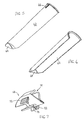
- Fig. 2
- eine Seitenquerschnittsansicht einer Düsenanordnung der Sämaschine,
- Fig. 3
- eine Seitenquerschnittsansicht einer Düsenanordnung der Sämaschine mit einem luftleitenden Einsatz,
- Fig. 4
- eine Seitenquerschnittsansicht einer Düsenanordnung der Sämaschine mit einem Produktaufnahmebegrenzungselement,
- Fig. 5
- eine perspektivische Ansicht des luftablenkenden Einsatzes von der Oberseite,
- Fig. 6
- eine perspektivische Ansicht des luftablenkenden Einsatzes von der Unterseite,
- Fig. 7
- eine perspektivische Ansicht des Produktaufnahmebegrenzungselements von der Unterseite,
- Fig. 8
- eine Vorderquerschnittsansicht der Düsenanordnung der Sämaschine,
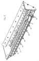
- Fig. 9
- eine perspektivische Vorderansicht und Teilquerschnittsansicht der Düsenanordnung der Sämaschine,
- Fig. 10
- eine perspektivische Vorderansicht der mit einer Rührwerkanordnung versehen Düsenanordnung und
- Fig. 11
- eine Querschnittsansicht der mit einer Rührwerkanordnung versehen Düsenanordnung.
- Fig. 1
- a side view of an agricultural seeder invention,
- Fig. 2
- a side cross-sectional view of a nozzle assembly of the drill,
- Fig. 3
- a side cross-sectional view of a nozzle assembly of the drill with an air-conducting insert,
- Fig. 4
- a side cross-sectional view of a nozzle assembly of the drill with a product receiving boundary element,
- Fig. 5
- a perspective view of the air deflecting insert from the top,
- Fig. 6
- a perspective view of the air deflecting insert from the bottom,
- Fig. 7
- a perspective view of the product receiving limiting element from the bottom,
- Fig. 8
- a front cross-sectional view of the nozzle assembly of the seeder,
- Fig. 9
- a front perspective view and partial cross-sectional view of the nozzle assembly of the seeder,
- Fig. 10
- a front perspective view of the provided with a stirrer assembly nozzle assembly and
- Fig. 11
- a cross-sectional view of the provided with a stirrer assembly nozzle assembly.
Eine landwirtschaftliche Sämaschine 10 enthält einen Rahmen 12, auf dem mehrere einzelne Pflanzeinheiten 14 montiert sind. Die Pflanzeinheiten 14 sind über ein Parallelogrammgestänge 16 mit dem Rahmen 12 verbunden, so dass sich die einzelnen Pflanzeinheiten 14 relativ zum Rahmen 12 bis zu einem begrenzten Maße auf und nieder bewegen können. Jede der einzelnen Pflanzeinheiten 14 enthält einen Saatguthilfsbehälter 18 zur Aufnahme von Saatgut, eine Saatgutdosiervorrichtung 20 zur Dosierung des vom Saatguthilfsbehälter 18 aufgenommenen Saatguts und einen Furchenöffner 22 zur Ausbildung einer Saatfurche auf einem Feld zur Aufnahme des von der Saatgutdosiervorrichtung 20 dosierten Saatguts. Das Saatgut wird durch ein Saatrohr 24 von der Saatgutdosiervorrichtung 20 in die Pflanzfurche geleitet. Eine Verschließvorrichtung 26 dient zum Verschließen der das Saatgut enthaltenden Pflanzfurche. In einer bevorzugten Ausführungsform ist die Saatgutdosiervorrichtung 20 eine Vakuumsaatgutdosiervorrichtung, obwohl auch andere Arten von Saatgutdosiervorrichtungen, die mechanische Baugruppen oder Überdruck verwenden, verwendet werden könnten. Hierbei sollte erwähnt werden, dass die Erfindung auch zum Ausbringen von Nichtsaatgut auf dem Feld genutzt werden könnte. Sowohl für Saat- als auch für Nichtsaatgut, kann die Pflanzeinheit 14 als Ausbringeinheit mit einem Hilfsbehälter zur Aufnahme eines Guts, einer Dosiervorrichtung zur Dosierung des vom Hilfsbehälter aufgenommenen Guts und einer Ausbringvorrichtung zum Ausbringen des dosierten Guts auf das Feld angesehen werden. Beispielsweise könnten ein chemikalischer Trockendünger oder Pestizide in den Hilfsbehälter geleitet, durch die Dosiervorrichtung dosiert und durch die Ausbringvorrichtung auf das Feld aufgebracht werden.An agricultural seeder 10 includes a
Der Hauptrahmen 12 trägt einen Hauptbehälter 30 und eine Druckluftpumpe 32. Die Druckluftpumpe 32 wird durch einen Hydraulikmotor angetrieben, wobei auch andere Motoranordnungen, wie z. B. elektrische Motoren für den Antrieb der Luftpumpe 32 eingesetzt werden könnten. Die Luftpumpe 32 fördert Druckluft durch einen Hauptluftschlauch 36 in einen Verteiler 34. Der Verteiler 34 ist aus einem hohlen, geschlossenen, rohrförmigen Träger des Rahmens 12 geformt. Der Verteiler 34 ist entsprechend der Anzahl der am Rahmen 12 enthaltenden Pflanzeinheiten 14 mit mehreren Verteilerauslassöffnungen versehen. Einzelne Luftversorgungsleitungen 38 erstrecken sich von den Verteilerauslassöffnungen und leiten Druckluft vom Verteiler 34 in die Strömungseingangsseite der Düsenanordnung 39. Die Düsenanordnung 39 ist auf dem Boden des Hauptbehälters 30 angeordnet. Durch die Schwerkraft gelangt das im Hauptbehälter 30 befindliche Gut in die Düsenanordnung 39. Die Düsenanordnung 39 ist mit einer Anzahl von Lufteingangskanälen 41 versehen, die der Anzahl von Luftversorgungsleitungen 38 entspricht. Die Lufteingangskanäle 41 sind quer entlang der Strömungseingangsseite zueinander beabstandet angeordnet. Die Strömungsausgangsseite der Düsenanordnung 39 ist mit einer Anzahl von Gutausgangskanälen 43 versehen, die der Anzahl der Luftversorgungsleitungen 38 entspricht. Die Gutausgangskanäle 43 sind ebenfalls quer entlang der Strömungsausgangsseite der Düsenanordnung 39 zueinander beabstandet angeordnet. Die Gutausgangskanäle 43 liegen gegenüber den Lufteingangskanälen 41. Jeder Lufteingangskanal 41 ist fluchtend zu einem entsprechenden Gutausgangskanal 43 ausgerichtet. Gutversorgungsschläuche 42 erstrecken sich von den Gutausgangskanälen 43 zu den einzelnen Hilfsbehältern 18 und leiten das im Luftstrom mitgeführte Gut zu den Hilfsbehältern 18.The
Die Düsenanordnung 39 ist mit einem konkavförmigen Boden 44 ausgebildet, welcher nach außen auseinanderlaufende Seitenwände 45, 46 enthält. Das Gut in Form von Saatgut oder Nichtsaatgut wird in den Hauptbehälter 30 durch einen Deckel 47 eingeführt. Bereiche der Düsenanordnung 39 können geöffnet werden und stellen eine Reinigungsöffnung 48 bereit. Die Reinigungsöffnung 48 ist durch einen Scharnierbolzen 50 schwenkbar mit der Düsenanordnung 39 verbunden. Die Reinigungsöffnung wird durch eine Verriegelung 52, welche mit den inneren Seitenwände 45, 46 des Hauptbehälters 30 in Verbindung steht, arretiert. Um die Reinigungsöffnung 48 zu öffnen, wird die Verriegelung 52 um 90° geschwenkt, so dass die Schenkel der Verriegelung 52 nicht länger mit den inneren Seitenwänden 45, 46 in Kontakt stehen. Die Reinigungsklappe 48 wird dann über den Scharnierbolzen 50 verschwenkt, so dass sie unterhalb des Scharnierbolzens 50 hängt. Zwischen der Reinigungsklappe 48 und der außenliegenden Oberfläche der nach außen auseinanderlaufenden Seitenwände 45, 46 ist, zur Abdichtung des Hauptbehälters 30 bei geschlossener Reinigungsklappe 48, eine elastische Gummischaumdichtung 56 angeordnet.The
Jeder Lufteingangskanal 41 und dazugehöriger Gutausgangskanal 43 ist aus zwei Kunststoffteilen ausgebildet. Die zwei Kunststoffteile sind mittels eingebauter Stecker, die am einen Teil ausgebildet sind, und Aufnahmeöffnungen, die am anderen Teil ausgebildet sind, zusammengesteckt. Der Lufteingangskanal 41 ist relativ zum konkavförmigen Boden 44 abwärtsgeneigt angeordnet und der Gutausgangskanal 43 ist entsprechend relativ zum konkavförmigen Boden 44 aufwärtsgeneigt angeordnet. Zwischen dem Lufteingangskanal 41 und dem Gutausgangskanal 43 erstreckt sich eine eingebaute Blende 58. Die Blende 58 läuft spitz zu und ist über dem Luftstrom, der durch den Lufteingangskanal 41 und dem Gutausgangskanal 43 verläuft, angeordnet. Der abwärtsgeneigte Lufteingangskanal 41 verhindert, dass Gut zurück in die Luftversorgungsleitung 38 gelangt, wohingegen der aufwärtsgerichtete Gutausgangskanal 43 verhindert, dass Gut in den Gutversorgungsschlauch 42 strömt und diesen verstopft.Each
Die benachbarten Kombinationen aus Lufteingangskanal 41 und Gutausgangskanal 43 sind in Querrichtung zueinander beabstandet angeordnet, so dass Saatgut oder Nichtsaatgut an beiden Seiten der Blenden 58 vorbei gelangen und sich unter den Blenden 58 anhäufen kann. Ein durch den Lufteingangskanal 41 in den Gutausgangskanal 43 strömender Luftstrom nimmt Gut aus der Anhäufung auf und fördert es durch den Gutversorgungsschlauch 42 in den Saatguthilfsbehälter 18. Die Förderung von Gut aus dem Hauptbehälter 30 in die Saatguthilfsbehälter 18 geschieht automatisch sobald Gut in den Saatguthilfsbehältern 18 benötigt wird. Sobald ein einzelner Saatguthilfsbehälter 18 sich mit Gut füllt, bedeckt sich der Guteinlasskanal 60 des Saatguthilfsbehälters 18 mit Gut, wodurch der Luftstrom blockiert und abgeschwächt wird, so dass der Luftstrom kein Gut im Hauptbehälter 30 mehr aufnimmt und in den Saatguthilfsbehälter 18 fördert.The adjacent combinations of
Im Gegensatz dazu ist der Guteinlasskanal 60 des Saatguthilfsbehälters 18 freigelegt, wenn das Gut durch die Saatgutdosiervorrichtung 20 aufgebraucht wurde, so dass der Luftstrom erneut Gut zur Förderung in den Saatguthilfsbehälter 18 aufnimmt. Auf diese Weise werden die Saatguthilfsbehälter 18 stets und automatisch mit Gut versorgt. Die Seitenwände der Saatguthilfsbehälter 18 sind zum Abbau des Luftdrucks im Saatguthilfsbehälter 18 mit Belüftungsöffnungen 61 versehen. Die Belüftungsöffnungen 61 können auch auf der Abdeckung der Saatguthilfsbehälter 18 angeordnet sein, solange sich die Belüftungsöffnungen 61 oberhalb der entsprechenden Guteinlasskanäle 60 befinden.In contrast, the Guteinlasskanal 60 of the
In einigen Fällen, in denen das Gut größere Partikel enthält, wie z. B. große Samenkörner (Mais und Sojabohnen), ist es für den Luftstrom schwierig, diese aufzunehmen. Um größere Samenkörner aufzunehmen, kann der Lufteingangskanal 41 mit einem Einsatz 62 versehen sein, welcher ein luftstromablenkendes Teil 64 enthält, durch das ein Teil des Luftstroms nach unten abgelenkt wird, um die Samenkörner in der Anhäufung aufzuwirbeln, so dass die Samenkörner von dem in den Gutausgangskanal 43 strömenden Luftstrom eingefangen werden. Der Einsatz 62 ist mit einem Passsteg 66 versehen, der in eine im Lufteingangskanal 41 ausgebildete Ausspaarung eingreift, um eine korrekte Positionierung des Einsatzes 62 und des luftstromablenkenden Teils zu gewährleisten.In some cases, where the material contains larger particles, such. B. large seeds (corn and soybeans), it is difficult for the air flow to accommodate them. To accommodate larger seeds, the
In anderen Fällen kann das Saatgut oder Nichtsaatgut zu leicht sein und auch schon durch einen leichten Luftstrom sofort mitgenommen werden. Um dieses Problem zu lösen, können die Blenden 58 mit einem Klippelement 68 (Produktaufnahmebegrenzungselement) versehen werden. Das Klippelement 68 kann an die Blende 58 aufgesteckt werden. Das Klippelement 68 enthält einen abgrenzenden Boden 70, mit dem die dem Luftstrom ausgesetzte Menge an Gut begrenzt wird. Das Klippelement 68 ist aus Kunststoff gefertigt und mit Spanngriffen 72 versehen. Durch Zusammendrücken der Spanngriffe 72 wird ein oberer Spalt 74 geöffnet, so dass das Klippelement 68 auf die Blende 58 aufgesteckt werden kann.In other cases, the seed or non-seed can be too light and even be taken away with a light stream of air. In order to solve this problem, the
In einer alternativen Ausführungsform kann der für die großen Samenkörner vorgesehene Einsatz 62 durch eine Rührwerkanordnung 80 ausgetauscht werden. Die Rührwerkanordnung 80 enthält eine Querstange 82 die sich quer über die Düsenanordnung 39 erstreckt. Die Querstange 82 ist mit mehreren sich radial erstreckenden Fingern 84 versehen. Wie in Fig. 10 gezeigt ist, sind die Finger in Querrichtung zueinander ausgerichtet.In an alternative embodiment, the
Die Querstange 82 wird durch ein von einem Motor 88 angetriebenes Getriebe 86 hin und her verdreht. In der unteren Totpunktstellung erstrecken sich die Finger 84 zwischen den einzelnen Düsen, welche durch die zueinander ausgerichteten Lufteingangskanäle 41 und Gutausgangskanäle 43 gebildet werden. Auf diese Weise überstreichen die Finger 84 den Bereich zwischen den Düsen. Die Getriebe/Motor-Anordnung 86, 88 verdreht die Querstange 82 einundfünfzigeinhalb Grad in beide Richtungen ausgehend von der unteren Totpunktstellung, wie sie in Fig. 11 dargestellt ist. Damit durchlaufen die Finger einen Winkel von einhundertdrei Grad.The
Claims (20)
- Seeding machine with:• a main hopper (30), which includes a nozzle assembly (39), into which the product contained in the main hopper (30) is directed, wherein the nozzle assembly (39) has an upstream side wall (45) and a downstream side wall (46),• several planting units (14) with a product metering device (20) and an applicator for applying the product to the field, wherein each product metering device (20) is connected via a product supply tube (42) to the downstream side wall (46) of the nozzle assembly (39), and• an air pump (32) pneumatically connected through several air supply hoses (38) to the upstream side wall (45) of the nozzle assembly (39)wherein the air pump (32) generates pressurised air, which is directed into the air supply hoses (38), wherein the number of air supply hoses (38) corresponds to the number of planting units (14) and each air supply hose (38) contains an air inlet (41) connected to the nozzle assembly (39) and located opposite the product outlet (43) of the product supply tube (42), so that the product located in the nozzle assembly (39) is taken up by the air stream when the air stream flows out of the air inlet (41) of the corresponding air supply hose (38) through the nozzle assembly (39) into the corresponding product outlet (43) of the product supply tube (42), and wherein the product supply tube (42) directs the product to the corresponding product metering device (20), characterised in that the nozzle assembly (39) is provided with a number of baffles (58) corresponding to the number of planting units (14), wherein the baffles (58) extend between and above the air inlets (41) of the air supply hoses (38) and the corresponding product outlets (43) of the product supply tubes (42).
- Seeding machine according to one of the preceding claims, characterised in that the air stream flows out of the air supply hose (38) beneath the baffles (58).
- Seeding machine according to one of the preceding claims, characterised in that each baffle (58) is configured to taper upwards to a point and spaces are formed between the adjacent baffles (58) so that the product drops to a bottom (44) of the nozzle assembly (39).
- Seeding machine according to one of the preceding claims, characterised in that the product outlets (43) of the product supply tubes (42) are directed upwards relative to the bottom (44) of the nozzle assembly (39).
- Seeding machine according to one of the preceding claims, characterised in that the air inlets (41) of the air supply hoses (38) are directed downwards relative to the bottom (44) of the nozzle assembly (39).
- Seeding machine according to one of the preceding claims, characterised in that the bottom (44) of the nozzle assembly (39) is concave and the upstream and downstream side walls (45, 46) diverge outwards from one another.
- Seeding machine according to one of the preceding claims, characterised in that each planting unit (14) is provided with an auxiliary hopper (18) positioned between the product inlet (60) and the product metering device (20).
- Seeding machine according to one of the preceding claims, characterised in that an air manifold (34) is included, which is pneumatically connected to the air pump (32) upstream of the air supply hose (38), wherein each of the air supply hoses (38) is pneumatically connected to the air manifold (34).
- Seeding machine according to Claim 8, characterised in that the manifold (34) is configured by a hollow part of a frame (12) supporting the main hopper (30).
- Seeding machine according to one of the preceding claims, characterised in that the nozzle assembly (39) is provided with a cleanout door (48), which is arranged below the air inlets (41) of the air supply hoses (3 8) and the product outlets (43) of the product supply tubes (42).
- Seeding machine according to one of the preceding claims, characterised in that the air inlets (41) of the air supply hoses (38) are provided with inserts (62), which contain an air deflecting portion (64), which deflects a portion of the air stream down towards the bottom (44) of the nozzle assembly (39) to agitate the product located on the bottom (44) of the nozzle assembly (39).
- Seeding machine according to one of the preceding claims, characterised in that the baffles (58) are provided with an element (68), which has an obstructing bottom (70) to limit the amount of product exposed to the air stream flowing between the air inlets (41) of the air supply hoses (38) and the product outlets (43) of the product supply tubes (42).
- Seeding machine according to Claim 12, characterised in that the element (68) is an attachment element in the form of a clip-on element.
- Seeding machine according to one of the preceding claims, characterised in that an agitator assembly (80) is contained in the nozzle assembly (39) to agitate product located in the nozzle assembly (39).
- Seeding machine according to Claim 14, characterised in that the agitator assembly (80) is provided with several fingers (84), which extend into the spaces formed between the adjacent baffles (58).
- Seeding machine according to Claim 14 or Claim 15, characterised in that the agitator assembly (80) includes a transverse rod (82) arranged above the baffles (58), wherein the transverse rod (82) comprises several fingers (84), which extend radially outwards from the transversely extending rod (82).
- Seeding machine according to Claim 15 or 16, characterised in that the fingers (84) are aligned transversely to one another on the transversely extending rod (82).
- Seeding machine according to one of Claims 15 to 17, characterised in that the transverse rod (82) can be rotated back and forth so that the fingers (84) agitate the product located in the nozzle assembly (39).
- Seeding machine according to one of Claims 14 to 18, characterised in that the transverse rod (82) can be rotated back and forth along an arc of one hundred and three degrees (103°).
- Seeding machine according to Claim 19, characterised in that the centre of the arc with an angle of one hundred and three degrees represents the bottom dead centre to the nozzle assembly (39).
Applications Claiming Priority (5)
| Application Number | Priority Date | Filing Date | Title |
|---|---|---|---|
| US214970 | 1988-07-05 | ||
| US10/214,970 US6609468B1 (en) | 2002-08-08 | 2002-08-08 | Product on demand delivery system having an agitator assembly |
| US214957 | 2002-08-08 | ||
| US10/214,957 US6688244B1 (en) | 2002-08-08 | 2002-08-08 | Product on demand delivery system |
| PCT/EP2003/006675 WO2004017712A1 (en) | 2002-08-08 | 2003-06-25 | Seeding machine |
Publications (2)
| Publication Number | Publication Date |
|---|---|
| EP1526766A1 EP1526766A1 (en) | 2005-05-04 |
| EP1526766B1 true EP1526766B1 (en) | 2006-05-03 |
Family
ID=31949770
Family Applications (1)
| Application Number | Title | Priority Date | Filing Date |
|---|---|---|---|
| EP03792162A Expired - Lifetime EP1526766B1 (en) | 2002-08-08 | 2003-06-25 | Seeding machine |
Country Status (8)
| Country | Link |
|---|---|
| EP (1) | EP1526766B1 (en) |
| AU (1) | AU2003249870A1 (en) |
| DE (1) | DE50303220D1 (en) |
| ES (1) | ES2259154T3 (en) |
| PL (1) | PL214280B1 (en) |
| RU (1) | RU2314668C2 (en) |
| UA (1) | UA80434C2 (en) |
| WO (1) | WO2004017712A1 (en) |
Families Citing this family (14)
| Publication number | Priority date | Publication date | Assignee | Title |
|---|---|---|---|---|
| CA2977467A1 (en) | 2016-10-11 | 2018-04-11 | Deere & Company | Seeding system |
| US10942053B2 (en) | 2018-05-14 | 2021-03-09 | Deere & Company | Seeding system |
| US11483963B2 (en) | 2019-12-24 | 2022-11-01 | Cnh Industrial America Llc | Particle delivery system of an agricultural row unit |
| US11553638B2 (en) | 2019-12-24 | 2023-01-17 | Cnh Industrial America Llc | Particle delivery system of an agricultural row unit |
| US11564346B2 (en) | 2019-12-24 | 2023-01-31 | Cnh Industrial America Llc | Particle delivery system of an agricultural row unit |
| US11589500B2 (en) | 2019-12-24 | 2023-02-28 | Cnh Industrial America Llc | Particle delivery system of an agricultural row unit |
| US11564344B2 (en) | 2019-12-24 | 2023-01-31 | Cnh Industrial America Llc | Particle delivery system of an agricultural row unit |
| US11596095B2 (en) | 2019-12-24 | 2023-03-07 | Cnh Industrial America Llc | Particle delivery system of an agricultural row unit |
| US11490558B2 (en) | 2019-12-24 | 2022-11-08 | Cnh Industrial America Llc | Particle delivery system of an agricultural row unit |
| US11516958B2 (en) | 2019-12-24 | 2022-12-06 | Cnh Industrial America Llc | Particle delivery system of an agricultural row unit |
| US11523555B2 (en) | 2019-12-24 | 2022-12-13 | Cnh Industrial America Llc | Particle delivery system of an agricultural row unit |
| US11553639B2 (en) | 2019-12-24 | 2023-01-17 | Cnh Industrial America Llc | Particle delivery system of an agricultural row unit |
| US11523556B2 (en) | 2019-12-24 | 2022-12-13 | Cnh Industrial America Llc | Particle delivery system of an agricultural row unit |
| US11582899B2 (en) | 2019-12-24 | 2023-02-21 | Cnh Industrial America Llc | Particle delivery system of an agricultural row unit |
Family Cites Families (8)
| Publication number | Priority date | Publication date | Assignee | Title |
|---|---|---|---|---|
| GB593983A (en) * | 1945-06-21 | 1947-10-30 | Wallace James Parker | Improvements in or relating to devices for sowing seeds |
| US3804036A (en) * | 1972-10-05 | 1974-04-16 | E Seifert | Air induction apparatus for seed drill tube |
| US4296695A (en) * | 1978-04-03 | 1981-10-27 | Wil-Rich, Inc. | Seeding device with air distribution system |
| US4503786A (en) * | 1980-12-24 | 1985-03-12 | Tautfest Rexford L | Grain drill with sealed bin air-powered distribution |
| US4514114A (en) * | 1982-07-08 | 1985-04-30 | Fuss Albert K | Seed and/or fertilizer distributor |
| IT1182626B (en) * | 1985-10-18 | 1987-10-05 | Mec Off | PNEUMATIC SEED DRILL CONVERTIBLE INTO FERTILIZER |
| US4705220A (en) * | 1985-11-25 | 1987-11-10 | Gandy Company | Granular applicator with interchangeable metering wheels |
| US5161473A (en) * | 1991-05-17 | 1992-11-10 | Deere & Company | Seed distribution system and method for a seeding implement |
-
2003
- 2003-06-25 RU RU2005106290/12A patent/RU2314668C2/en not_active IP Right Cessation
- 2003-06-25 WO PCT/EP2003/006675 patent/WO2004017712A1/en not_active Application Discontinuation
- 2003-06-25 ES ES03792162T patent/ES2259154T3/en not_active Expired - Lifetime
- 2003-06-25 AU AU2003249870A patent/AU2003249870A1/en not_active Abandoned
- 2003-06-25 DE DE50303220T patent/DE50303220D1/en not_active Expired - Lifetime
- 2003-06-25 EP EP03792162A patent/EP1526766B1/en not_active Expired - Lifetime
- 2003-06-25 PL PL374105A patent/PL214280B1/en unknown
- 2003-06-25 UA UAA200501227A patent/UA80434C2/en unknown
Also Published As
| Publication number | Publication date |
|---|---|
| RU2005106290A (en) | 2006-01-20 |
| DE50303220D1 (en) | 2006-06-08 |
| ES2259154T3 (en) | 2006-09-16 |
| PL214280B1 (en) | 2013-07-31 |
| EP1526766A1 (en) | 2005-05-04 |
| PL374105A1 (en) | 2005-09-19 |
| RU2314668C2 (en) | 2008-01-20 |
| AU2003249870A1 (en) | 2004-03-11 |
| UA80434C2 (en) | 2007-09-25 |
| WO2004017712A1 (en) | 2004-03-04 |
Similar Documents
| Publication | Publication Date | Title |
|---|---|---|
| EP1591000B1 (en) | Delivery system for agricultural products | |
| US7213525B2 (en) | Nozzle assembly for product-on-demand delivery system | |
| EP1526766B1 (en) | Seeding machine | |
| EP1593295B1 (en) | Delivery system for an agricultural product | |
| DE69623295T2 (en) | SEED MEASURING METHOD AND DEVICE | |
| CA2435408C (en) | Product on demand delivery system | |
| DE102019201393A1 (en) | Row unit for a seeder with pneumatic conveying system | |
| US7025010B2 (en) | Flow splitter arrangement for series fed product application units | |
| CA2151020E (en) | Multi compartment air seeder | |
| DE69921936T2 (en) | Inductor device for containers in pneumatic seed drills | |
| DE102019201388A1 (en) | Row unit for a seeder with pneumatic conveying system | |
| US6609468B1 (en) | Product on demand delivery system having an agitator assembly | |
| EP1428420B1 (en) | Seed Metering System | |
| EP0799560A2 (en) | Exhaust air conduit for pneumatic distributor | |
| WO1999008503A1 (en) | Distributor system of a sawing device | |
| DE2629278A1 (en) | PROCESS AND DEVICE FOR REGULATING Litter SUPPLY ON COMPRESSED AIR-OPERATED SPREAD DISTRIBUTION AND DOSING MACHINES, IN PARTICULAR SAE MACHINES | |
| DE102019201399A1 (en) | SERIES OF SEWING MACHINES WITH PNEUMATIC SEED LOADING | |
| EP1504642B1 (en) | Seeder | |
| EP4199691A1 (en) | Grain-singulating apparatus with separating device, and seeder with grain-singulating apparatus | |
| DE19549577C3 (en) | Agricultural distributor | |
| DE3403540C1 (en) | Dosing machine for granular material | |
| EP3945767A1 (en) | Distribution device for granular material | |
| EP3917304B1 (en) | Material introduction sluice for a distribution machine, and distribution machine | |
| DE2241534C3 (en) | Dosing device for pneumatically operated distribution systems | |
| DE3515362A1 (en) | Apparatus for spreading pourable material, especially fertiliser |
Legal Events
| Date | Code | Title | Description |
|---|---|---|---|
| PUAI | Public reference made under article 153(3) epc to a published international application that has entered the european phase |
Free format text: ORIGINAL CODE: 0009012 |
|
| 17P | Request for examination filed |
Effective date: 20041117 |
|
| AK | Designated contracting states |
Kind code of ref document: A1 Designated state(s): AT BE BG CH CY CZ DE DK EE ES FI FR GB GR HU IE IT LI LU MC NL PT RO SE SI SK TR |
|
| AX | Request for extension of the european patent |
Extension state: AL LT LV MK |
|
| GRAP | Despatch of communication of intention to grant a patent |
Free format text: ORIGINAL CODE: EPIDOSNIGR1 |
|
| DAX | Request for extension of the european patent (deleted) | ||
| RBV | Designated contracting states (corrected) |
Designated state(s): DE ES FR HU IT |
|
| GRAS | Grant fee paid |
Free format text: ORIGINAL CODE: EPIDOSNIGR3 |
|
| GRAA | (expected) grant |
Free format text: ORIGINAL CODE: 0009210 |
|
| AK | Designated contracting states |
Kind code of ref document: B1 Designated state(s): DE ES FR HU IT |
|
| REF | Corresponds to: |
Ref document number: 50303220 Country of ref document: DE Date of ref document: 20060608 Kind code of ref document: P |
|
| REG | Reference to a national code |
Ref country code: ES Ref legal event code: FG2A Ref document number: 2259154 Country of ref document: ES Kind code of ref document: T3 |
|
| REG | Reference to a national code |
Ref country code: HU Ref legal event code: AG4A Ref document number: E000529 Country of ref document: HU |
|
| ET | Fr: translation filed | ||
| PLBE | No opposition filed within time limit |
Free format text: ORIGINAL CODE: 0009261 |
|
| STAA | Information on the status of an ep patent application or granted ep patent |
Free format text: STATUS: NO OPPOSITION FILED WITHIN TIME LIMIT |
|
| 26N | No opposition filed |
Effective date: 20070206 |
|
| PGFP | Annual fee paid to national office [announced via postgrant information from national office to epo] |
Ref country code: ES Payment date: 20140626 Year of fee payment: 12 Ref country code: IT Payment date: 20140624 Year of fee payment: 12 |
|
| PGFP | Annual fee paid to national office [announced via postgrant information from national office to epo] |
Ref country code: HU Payment date: 20140606 Year of fee payment: 12 |
|
| PG25 | Lapsed in a contracting state [announced via postgrant information from national office to epo] |
Ref country code: IT Free format text: LAPSE BECAUSE OF NON-PAYMENT OF DUE FEES Effective date: 20150625 |
|
| PG25 | Lapsed in a contracting state [announced via postgrant information from national office to epo] |
Ref country code: HU Free format text: LAPSE BECAUSE OF NON-PAYMENT OF DUE FEES Effective date: 20150626 |
|
| REG | Reference to a national code |
Ref country code: FR Ref legal event code: PLFP Year of fee payment: 14 |
|
| REG | Reference to a national code |
Ref country code: FR Ref legal event code: PLFP Year of fee payment: 15 |
|
| PG25 | Lapsed in a contracting state [announced via postgrant information from national office to epo] |
Ref country code: ES Free format text: LAPSE BECAUSE OF NON-PAYMENT OF DUE FEES Effective date: 20150626 |
|
| REG | Reference to a national code |
Ref country code: FR Ref legal event code: PLFP Year of fee payment: 16 |
|
| REG | Reference to a national code |
Ref country code: ES Ref legal event code: FD2A Effective date: 20180704 |
|
| PGFP | Annual fee paid to national office [announced via postgrant information from national office to epo] |
Ref country code: DE Payment date: 20220519 Year of fee payment: 20 |
|
| PGFP | Annual fee paid to national office [announced via postgrant information from national office to epo] |
Ref country code: FR Payment date: 20220627 Year of fee payment: 20 |
|
| REG | Reference to a national code |
Ref country code: DE Ref legal event code: R071 Ref document number: 50303220 Country of ref document: DE |