EP0513402A1 - Procédé de compensation de non-linéarité pour un circuit amplificateur à temps de passage du signal fort - Google Patents
Procédé de compensation de non-linéarité pour un circuit amplificateur à temps de passage du signal fort Download PDFInfo
- Publication number
- EP0513402A1 EP0513402A1 EP19910106653 EP91106653A EP0513402A1 EP 0513402 A1 EP0513402 A1 EP 0513402A1 EP 19910106653 EP19910106653 EP 19910106653 EP 91106653 A EP91106653 A EP 91106653A EP 0513402 A1 EP0513402 A1 EP 0513402A1
- Authority
- EP
- European Patent Office
- Prior art keywords
- amplifier circuit
- signal
- input signal
- coefficients
- output signal
- Prior art date
- Legal status (The legal status is an assumption and is not a legal conclusion. Google has not performed a legal analysis and makes no representation as to the accuracy of the status listed.)
- Withdrawn
Links
Images


Classifications
-
- H—ELECTRICITY
- H03—ELECTRONIC CIRCUITRY
- H03H—IMPEDANCE NETWORKS, e.g. RESONANT CIRCUITS; RESONATORS
- H03H21/00—Adaptive networks
- H03H21/0012—Digital adaptive filters
- H03H21/0025—Particular filtering methods
- H03H21/0027—Particular filtering methods filtering in the frequency domain
-
- H—ELECTRICITY
- H03—ELECTRONIC CIRCUITRY
- H03F—AMPLIFIERS
- H03F1/00—Details of amplifiers with only discharge tubes, only semiconductor devices or only unspecified devices as amplifying elements
- H03F1/32—Modifications of amplifiers to reduce non-linear distortion
- H03F1/3241—Modifications of amplifiers to reduce non-linear distortion using predistortion circuits
- H03F1/3247—Modifications of amplifiers to reduce non-linear distortion using predistortion circuits using feedback acting on predistortion circuits
Definitions
- the invention relates to a method for compensating for non-linearities of an amplifier circuit with a pronounced signal throughput time, in which an input signal s (t) is amplified to an output signal y (t) using a predetermined amplifier circuit (e.g. power amplifier for audio signals), which has non-linearities,
- a predetermined amplifier circuit e.g. power amplifier for audio signals
- Amplifier circuits in particular high-performance sound amplifiers, such as those used for modulating radio transmitters in the LW, MW and KW range, are usually fraught with non-linearities which must be eliminated.
- the classic solution for linearizing the characteristic provides for feedback of the output signal (feedback). The degree of this feedback depends on the characteristics of the amplifier in the non-feedback state.
- the object of the invention is to provide a method of the type mentioned at the outset, which ensures linear amplification, in particular for audio signals, using modern high-performance amplifiers and is free from instabilities.
- feed forward control which does not include a closed loop (open loop). It is based on the same amplifier model as that Feedback solution, but uses the determined coefficients in a different way.
- feed forward control in a predistortion filter in the sense of an open feedforward control using only the given input signal x (t) of the amplifier circuit and the coefficients k 1, ..., k L and the throughput time t d of the amplifier circuit to an input signal s (t) additive compensation signal c (t) is formed. This compensation signal c (t) is added to the input signal s (t) (predistortion). Finally, the resulting sum signal is fed as an input signal x (t) to the amplifier circuit, which has non-linearities.
- the compensation signal is first constructed in the Fourier space and then brought into the time domain by means of a fast Fourier transformation (FFT).
- FFT fast Fourier transformation
- the Fourier coefficients C n (i) of the additive compensation signal c (t) are according to the relationship determined.
- K -K c k1 (i) ⁇ n (i) [jn ⁇ T s / N + K c k12 (i) ⁇ n (i)] ⁇ 1
- K c is an arbitrarily definable constant that has no influence on the control principle. However, if it is chosen appropriately, the convergence of the compensation method can be improved.
- ⁇ (i) is determined according to the invention using the determined coefficients k 1 (i), ..., k L (i) according to the method of least squares. If ⁇ (i) has been determined from the over-determined system of equations, then the throughput time t d (i-1) is also defined (apart from integer multiples of T s ).
- the immediate input signal x (t) of the non-linear amplifier circuit is delayed in accordance with the first approximation t d0 of the throughput time compared to the output signal y (t).
- a high-performance amplifier with a linear characteristic is therefore available to the user of the circuit according to the invention.
- the preferably digital predistortion filter can namely easily be accommodated in the housing of the power amplifier in question.
- FIG. 1 shows a circuit diagram for wiring an amplifier circuit 1 in accordance with the invention.
- the predefined amplifier circuit for example a high-power amplifier, has a non-linear characteristic and a pronounced signal throughput time t d . This has to As a result, intermodulation would occur if the input signal s (t) were amplified directly without any precautions.
- the input signal s (t) is therefore first fed to a predistortion filter 3 which carries out a suitable predistortion.
- the predistorted signal x (t) is then raised by the amplifier circuit 1 to the required power level.
- the parameters of the predistortion are with an identification processor 2 from input and output signal x (t) and. y (t) of the amplifier circuit 1 is obtained.
- predistortion represents an essential feature of the invention. It will be explained in detail below taking into account the mathematical background.
- FIG. 2 The principle of identification emerges from FIG. 2. It is based on the evaluation of the input and output signals x (t) and. y (t) of the amplifier circuit 1 and runs essentially on the digital level and in the Fourier space.
- the input signal x (t) is first delayed by a delay element 20 by a fixed predetermined time interval t d0 .
- the delay corresponds in a first approximation to the transit time t d of the signal that actually occurs in the amplifier circuit.
- the delayed input signal x (tt d0 ) is then sampled and digitized in an A / D converter 21 at a rate 1 / T s .
- equations (V) and (VI) can of course be evaluated with the same effect, which assume that the quadratic and cubic signals x2 (t) and. x3 (t) can be calculated and then the FFT operation is performed:
- the output signal y (t) of the amplifier circuit 1 is digitized in the same way as x (t) (A / D converter 24) and Fourier-transformed (FFT computer 25).
- y m (i) denotes the digitized output signal.
- ⁇ 2 are now based on the auxiliary variables , ..., L ⁇ - and the Fourier coefficient Y n (i) the parameters of the model, ie the coefficients k1, k2, k3 and the lead time t d estimated.
- the 2N equations of the form used belong to the 2N samples per calculation cycle.
- t d can also be calculated in a modified manner.
- the invention is therefore not limited to the method for determining the throughput time just described.
- the amplifier characteristic is constantly identified anew, so that the end result is adaptive compensation of the non-linearity.
- the identification processor described here is therefore only to be understood as one of several equivalent options. Accordingly, the invention is not to be seen in this narrow scope.
- the time delay of the input signal x (t) in the identification processor can also only be introduced at the digital level.
- the relevant formulas can also be evaluated in other ways (e.g. in several individual steps). It is only important that the end result is a solution that can be expressed mathematically in the explicitly given way.
- the complex quantities A n (i) and B n (i) supplied by the identification processor 2 are delayed by a control cycle in a delay element 31. Then with a first and a second multiplier 32 and 33, the two summands A n (i-1) k2 (i) and B n (i-1) k3 (i) are formed and added in a summing element 34. The resulting sum is weighted in a further multiplier 35 by a certain factor -K.
- the Fourier coefficients C n (i) of the correction signal are thus available.
- An FFT 1 computer 36 uses the fast inverse Fourier transformation to determine the digital correction signal c m (i) in the time domain, which is finally converted into an analog signal c (t) by a D / A converter 37 and to the input signal s (t) is added (summing element 38).
- the weighting factor -K can optionally be determined from one of the following two relationships: or K c denotes a freely selectable constant (gain) that does not affect the predistortion as such, but only its convergence behavior.
- the weighting factor is determined in a computing element 30.
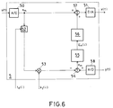
- FIGS. 4 and 5 show an example of a predistortion filter 4 based on the feedback principle.
- Amplifier circuit 1 and identification processor 2 are switched and designed as in the first embodiment.
- the input signal s (t) is passed, among other things, to an adjustable delay element 48 which introduces a time delay corresponding to the estimated throughput time t d (i).
- the delayed input signal is divided into two paths. In one generates a partial signal generator 49 a partial signal ⁇ e / ⁇ c of the form which is subsequently multiplied in a multiplier 42 by a fixed weighting factor -K c . In the other path there is an amplification with the coefficient k 1 (i) (multiplier 40).
- the difference signal e (t) is multiplied by the partial signal ⁇ e / ⁇ c (multiplier 43) and then integrated on the one hand in the integrator 45 and on the other hand multiplied by the determined throughput time t d (multiplier 44) according to
- the compensation signal c (t) is added to the undelayed input signal s (t) (summing element 47).
- the desired input signal x (t) is thus available to the amplifier circuit.
- the input signal s (t) resp. the output signal y (t) of the amplifier circuit 1 are respectively from an A / D converter 50. 58 scanned and digitized.
- the digital input signal s m (i) is delayed in an adjustable delay element 52 in accordance with the determined throughput time t d (i) and amplified with the linear coefficient k 1 (i) (multiplier 53).
- the input signal processed in this way is generated by the digitized output signal y m subtracted (summing element 54).
- the resulting (digital) difference signal e m (i) is subjected to a fast Fourier transformation in an FFT computer 55:
- the error signal generator 56 generates the desired error signal c m (i):
- the identification according to the invention and the compensation (predistortion) can also be used alone.
- the predistortion can certainly be based on a different type of identification, provided the latter provides the desired coefficients and processing times.
- the invention enables the linearization of non-linear characteristic curves, as are required in particular in the case of high-performance amplifiers in communications technology.
Landscapes
- Physics & Mathematics (AREA)
- Nonlinear Science (AREA)
- Engineering & Computer Science (AREA)
- Power Engineering (AREA)
- Amplifiers (AREA)
Priority Applications (1)
| Application Number | Priority Date | Filing Date | Title |
|---|---|---|---|
| EP19910106653 EP0513402A1 (fr) | 1991-04-24 | 1991-04-24 | Procédé de compensation de non-linéarité pour un circuit amplificateur à temps de passage du signal fort |
Applications Claiming Priority (1)
| Application Number | Priority Date | Filing Date | Title |
|---|---|---|---|
| EP19910106653 EP0513402A1 (fr) | 1991-04-24 | 1991-04-24 | Procédé de compensation de non-linéarité pour un circuit amplificateur à temps de passage du signal fort |
Publications (1)
| Publication Number | Publication Date |
|---|---|
| EP0513402A1 true EP0513402A1 (fr) | 1992-11-19 |
Family
ID=8206658
Family Applications (1)
| Application Number | Title | Priority Date | Filing Date |
|---|---|---|---|
| EP19910106653 Withdrawn EP0513402A1 (fr) | 1991-04-24 | 1991-04-24 | Procédé de compensation de non-linéarité pour un circuit amplificateur à temps de passage du signal fort |
Country Status (1)
| Country | Link |
|---|---|
| EP (1) | EP0513402A1 (fr) |
Cited By (5)
| Publication number | Priority date | Publication date | Assignee | Title |
|---|---|---|---|---|
| WO1996031946A3 (fr) * | 1995-04-05 | 1996-12-27 | Nokia Telecommunications Oy | Lineariseur destine a la linearisation d'une composante non-lineaire commandee par une tension de commande |
| WO2001003287A1 (fr) * | 1999-06-30 | 2001-01-11 | Wireless Systems International Limited | Reduction de distorsion de signaux |
| WO2001031778A1 (fr) * | 1999-10-26 | 2001-05-03 | Telefonaktiebolaget Lm Ericsson (Publ) | Linearisation adaptative d'amplificateurs de puissance |
| EP1152525A3 (fr) * | 2000-05-01 | 2006-08-16 | Sony Corporation | Dispositif de compensation de distorsion |
| CN117289250A (zh) * | 2023-09-26 | 2023-12-26 | 希烽光电科技(南京)有限公司 | 一种非线性补偿的校正系统、方法、设备及存储介质 |
-
1991
- 1991-04-24 EP EP19910106653 patent/EP0513402A1/fr not_active Withdrawn
Non-Patent Citations (4)
| Title |
|---|
| IEEE INTERNATIONAL CONFERENCE ON COMMUNICATIONS BOSTONICC/89 WORLD PROSPERITY THROUGH COMMUNICATIONS SHERATON BOSTON HOTEL Bd. 1, 11. Juni 1989, BOSTON,MA Seiten 286 - 291; G. KARAM ET AL: 'Improved Data Predistortion Using Intersymbol Interpolation' * |
| IEEE INTERNATIONAL CONFERENCE ON COMMUNICATIONS BOSTONICC/89 WORLD PROSPERITY THROUGH COMMUNICATIONS SHERATON BOSTON HOTEL Bd. 3, 11. Juni 1989, BOSTON,MA Seiten 1468 - 1472; R.BLUM ET AL: 'Modeling Nonlinear Amplifiers for Communication Simulation' * |
| PATENT ABSTRACTS OF JAPAN vol. 12, no. 499 (P-807)27. Dezember 1988 & JP-A-63 208 913 ( SHINKEN K.K. ) 30. August 1988 * |
| PROCEEDINGS OF THE IEEE. Bd. 76, Nr. 10, Oktober 1988, NEW YORK US Seiten 1383 - 1385; J.C. LEE S.K. MITRA: 'On The Block Least Squares Adaptive Digital Filters Realized Using the Fast Fourier Transform' * |
Cited By (9)
| Publication number | Priority date | Publication date | Assignee | Title |
|---|---|---|---|---|
| WO1996031946A3 (fr) * | 1995-04-05 | 1996-12-27 | Nokia Telecommunications Oy | Lineariseur destine a la linearisation d'une composante non-lineaire commandee par une tension de commande |
| US5847604A (en) * | 1995-04-05 | 1998-12-08 | Nokia Telecommunications Oy | Linearizer for linearizing a non-linear component controlled by control voltage |
| WO2001003287A1 (fr) * | 1999-06-30 | 2001-01-11 | Wireless Systems International Limited | Reduction de distorsion de signaux |
| US7106806B1 (en) | 1999-06-30 | 2006-09-12 | Andrew Corporation | Reducing distortion of signals |
| WO2001031778A1 (fr) * | 1999-10-26 | 2001-05-03 | Telefonaktiebolaget Lm Ericsson (Publ) | Linearisation adaptative d'amplificateurs de puissance |
| US6246286B1 (en) | 1999-10-26 | 2001-06-12 | Telefonaktiebolaget Lm Ericsson | Adaptive linearization of power amplifiers |
| JP2003513498A (ja) * | 1999-10-26 | 2003-04-08 | テレフオンアクチーボラゲット エル エム エリクソン(パブル) | 電力増幅器の適応線形化 |
| EP1152525A3 (fr) * | 2000-05-01 | 2006-08-16 | Sony Corporation | Dispositif de compensation de distorsion |
| CN117289250A (zh) * | 2023-09-26 | 2023-12-26 | 希烽光电科技(南京)有限公司 | 一种非线性补偿的校正系统、方法、设备及存储介质 |
Similar Documents
| Publication | Publication Date | Title |
|---|---|---|
| EP0465709A1 (fr) | Procédé de compensation des produits non linéaires d'un amplificateur | |
| DE69315723T2 (de) | Schaltkreis zur Korrektur von Verzerrungen in Empfängern | |
| DE60006102T2 (de) | Rundfunkübertragungssystem mit verteilter korrektur | |
| DE69528028T2 (de) | Aktive Lärm und Vibration Kontrollanordnung mit Rücksicht auf Zeitvariationen in der Anordnung unter Benutzung des residuellen Signals zur Erzeugung des Probesignals | |
| DE69718304T2 (de) | Adaptive verzerrungskompensationsschaltung für verstärker | |
| DE602005006119T2 (de) | Editierverfahren für Konfigurationsdaten eines Telekommunikationssystems sowie Computerprodukt und Server dafür | |
| DE69716935T2 (de) | Adaptive digitale vorwärtsgekoppelte Korrektur für HF Leistungsverstärker | |
| DE3880228T2 (de) | Digitaler Echokompensator. | |
| DE60001071T2 (de) | Verfahren und vorrichtung zur linearisierung eines verstärkers | |
| DE3854763T2 (de) | Verfahren zum Überprüfen eines Verstärkers zur Feststellung von durch Intermodulationsprodukte verursachte Verzerrungscharakteristiken. | |
| EP0656737B1 (fr) | Prothèse auditive avec suppression du couplage acoustique | |
| DE69030308T2 (de) | Linearer Verstärker mit automatischer Einstellung von Verstärkung und Phase der Vorwärtsgekoppelten Schleife | |
| DE69934930T2 (de) | Vorrichtung mit einem Leistungsverstärker mit einem vorwärtsgekoppelten Linearisierer unter Verwendung eines Nachlaufalgorithmus | |
| EP0243898B1 (fr) | Circuit pour la compensation en série des non-linéarités d'un amplificateur | |
| DE69935942T2 (de) | Vorwärtsgeregelter Linearisierer eines schnellen adaptiven Breitbandleistungsverstärkers unter Verwendung eines RLS Parameter benützenden nachsteuernden Algorithsmus | |
| DE69925887T2 (de) | Dynamische vorverrzerrungskompensation für einen leistungsverstärker | |
| DE69929964T2 (de) | Adaptive vorspannungseinstellung in einem leistungsverstärker | |
| DE69423240T2 (de) | Verfahren und vorrichtung für quadratische interpolation | |
| DE60014175T2 (de) | Verfahren und vorrichtung zum kompensieren von nicht-linearitäten und zeitvarianten änderungen einer übertragungsfunktion wirksam auf ein eingangssignal | |
| DE69201297T2 (de) | Ultraschnelle Differenzverstärker. | |
| DE60313036T2 (de) | Signaljustierung basierend auf phasenfehler | |
| EP0513402A1 (fr) | Procédé de compensation de non-linéarité pour un circuit amplificateur à temps de passage du signal fort | |
| DE2412031C3 (de) | Gegentaktverstärker | |
| DE60002437T2 (de) | Signalverarbeitungsvorrichtung | |
| DE19824171B4 (de) | Verfahren und Verarbeitungssystem zum iterativen Aktualisieren der Koeffizienten eines adaptiven Filters |
Legal Events
| Date | Code | Title | Description |
|---|---|---|---|
| PUAI | Public reference made under article 153(3) epc to a published international application that has entered the european phase |
Free format text: ORIGINAL CODE: 0009012 |
|
| AK | Designated contracting states |
Kind code of ref document: A1 Designated state(s): AT BE CH DE DK ES FR GB GR IT LI LU NL SE |
|
| RBV | Designated contracting states (corrected) |
Designated state(s): DE FR GB |
|
| 17P | Request for examination filed |
Effective date: 19930429 |
|
| RAP1 | Party data changed (applicant data changed or rights of an application transferred) |
Owner name: THOMCAST AG |
|
| RIN1 | Information on inventor provided before grant (corrected) |
Inventor name: PURI, NARINDRA NATH, PROF.DR. |
|
| STAA | Information on the status of an ep patent application or granted ep patent |
Free format text: STATUS: THE APPLICATION IS DEEMED TO BE WITHDRAWN |
|
| 18D | Application deemed to be withdrawn |
Effective date: 19951101 |