EP0511009B1 - Apparatus and method for transferring material to subaqueous levels - Google Patents
Apparatus and method for transferring material to subaqueous levels Download PDFInfo
- Publication number
- EP0511009B1 EP0511009B1 EP92303726A EP92303726A EP0511009B1 EP 0511009 B1 EP0511009 B1 EP 0511009B1 EP 92303726 A EP92303726 A EP 92303726A EP 92303726 A EP92303726 A EP 92303726A EP 0511009 B1 EP0511009 B1 EP 0511009B1
- Authority
- EP
- European Patent Office
- Prior art keywords
- vessel
- subaqueous
- wing
- members
- water
- Prior art date
- Legal status (The legal status is an assumption and is not a legal conclusion. Google has not performed a legal analysis and makes no representation as to the accuracy of the status listed.)
- Expired - Lifetime
Links
Images


Classifications
-
- B—PERFORMING OPERATIONS; TRANSPORTING
- B63—SHIPS OR OTHER WATERBORNE VESSELS; RELATED EQUIPMENT
- B63B—SHIPS OR OTHER WATERBORNE VESSELS; EQUIPMENT FOR SHIPPING
- B63B27/00—Arrangement of ship-based loading or unloading equipment for cargo or passengers
- B63B27/08—Arrangement of ship-based loading or unloading equipment for cargo or passengers of winches
-
- B—PERFORMING OPERATIONS; TRANSPORTING
- B09—DISPOSAL OF SOLID WASTE; RECLAMATION OF CONTAMINATED SOIL
- B09B—DISPOSAL OF SOLID WASTE NOT OTHERWISE PROVIDED FOR
- B09B1/00—Dumping solid waste
- B09B1/002—Sea dumping
-
- B—PERFORMING OPERATIONS; TRANSPORTING
- B63—SHIPS OR OTHER WATERBORNE VESSELS; RELATED EQUIPMENT
- B63B—SHIPS OR OTHER WATERBORNE VESSELS; EQUIPMENT FOR SHIPPING
- B63B27/00—Arrangement of ship-based loading or unloading equipment for cargo or passengers
- B63B27/19—Other loading or unloading equipment involving an intermittent action, not provided in groups B63B27/04 - B63B27/18
-
- B—PERFORMING OPERATIONS; TRANSPORTING
- B63—SHIPS OR OTHER WATERBORNE VESSELS; RELATED EQUIPMENT
- B63H—MARINE PROPULSION OR STEERING
- B63H25/00—Steering; Slowing-down otherwise than by use of propulsive elements; Dynamic anchoring, i.e. positioning vessels by means of main or auxiliary propulsive elements
- B63H25/44—Steering or slowing-down by extensible flaps or the like
Definitions
- This invention relates to apparatus and a method for transferring material from the surface of a body of water to subaqueous depths, and in particular to deep sea bed locations.
- waste material is a major problem and is one which is increasing at an alarming rate.
- waste materials are disposed of in the sea. Some materials are simply dumped from ships or pumped into the water. Such surface dumping leads to widespread pollution of the surface waters due to dispersal of waste matter as it sinks towards the sea bed. This can have a deleterious affect on the marine environment over a wide area.
- An object of the present invention is to provide apparatus and a method for transporting material from the surface of a body of water to a subaqueous level (typically the sea bed) in an efficient manner.
- a method of disposal of waste material on subaqueous ground substantially without said material coming into contact with the surrounding water which comprises transporting said material to a location above a selected site for disposal, conveying said material in a vessel to a level at, or close to, said subaqueous ground, and depositing said material from said vessel onto said subaqueous ground, characterised in that said vessel travels under free-fall conditions for a first period, and thereafter is decelerated during a second period as it approaches said level.
- the process of waste disposal preferably takes place from a ship which may be held stationary over a selected subaqueous site by means of a dynamic positioning system comprising thrusters and satellite navigational aids.
- the ship advantageously has sensors (such as sonar transponders) mounted beneath the hull which allow monitoring of the sea bed and monitoring of any objects beneath the ship.
- the duration of the first and second periods is calculated as a function of depth.
- the calculation of these two periods may be performed prior to, or during, the descent of the vessel.
- the vessel is preferably provided with water jets affixed so as to point in a downward direction. These water jets may be used to form a hollow in the sea bed into which the waste material may be deposited.
- the vessel is advantageously provided with vent apertures equipped with non-return valves, which, in use, permit water to enter the vessel, displacing the material which is being deposited, but which prevent egress of the material.
- These apertures are open when the waste material is deposited in order to equalise the hydrostatic pressures inside and outside the vessel and thus to increase the rate of deposition of said material.
- These vent apertures are preferably left open as the vessel is drawn back up to the surface of the water so as to minimise water resistance.
- a vessel for transporting a material from a first location at the surface of a body of water to a second location at a predetermined subaqueous level, for example at the sea bed which vessel comprises a generally cylindrical body comprising a containment area and having an opening at its Upper end for receiving material which is to be transported by the vessel, and having at its lower end means for permitting egress of material held within the containment area once said vessel has reached its predetermined second location; characterised in that the vessel is provided, at a position intermediate its upper end and its centre of mass, with at least two wing-like members located on the exterior surface of the vessel at diametrally opposed positions; and is provided with means for pivoting said wing-like members between a first position in which they lie substantially flat against the exterior of the vessel and a second position in which they extend outwardly from the body of the vessel so as to present an increased surface area to the surrounding water and to provide thereby a decelerating effect on the motion of the vessel when
- the wing-like members are attached to the body of the vessel relatively close to the upper end thereof, for example at a position spaced from the upper end of the vessel by an amount equal to a value in the range from one tenth to one third of the axial length of the vessel. It is also preferred for the wing-like members to pivot upwardly and outwardly when moving from their first position to their second position. This arrangement maintains better stability during the descent of the vessel both during its normal descent velocity phase and when it is subject to the decelerating effect of the wing-like members.
- the body of the vessel itself, or the outer surface of the wing-like members are provided with baffles which serve to modify the "free fall" velocity of the vessel as it descends from the surface of the body of water.
- baffles may be fixed in orientation, or they may be under active control to permit them to move from a "feathered” arrangement, in which they present minimal area against the water, to an open position in which they present maximal area to the water.
- the wing-like members may be generally planar or they may be curved to correspond to the curvature of the exterior of the vessel body. Additionally, in some embodiments, the or each of the wing-like members may terminate in a short flange which can, for example, extend obliquely away from the body of the vessel when the wing-like members are in their closed (i.e. streamlined) position.
- the opening or openings in the upper section of the vessel preferably include one-way vents which permit material to enter the vessel while preventing any upward movement of material from inside the vessel. These vents permit hydrostatic equalisation during descent of the vessel from its sea surface location to the position at which its contents are to be evacuated.
- the lower end of the vessel is preferably formed to include doors which hinge outwardly to permit egress of material from within the vessel.
- the vessel preferably carries a control pack which allows remote or automatic operation of the doors. As the material exits via the open doors at the base of the vessel, the one-way vents at the upper end of the vessel may be used to allow water to enter the vessel, maintaining hydrostatic equalisation during the emptying operation.
- the containment body preferably has its internal surface provided with a non-stick coating.
- the ship may be held on station at the disposal site by means of satellite navigational aids and thrusters and also by means of sensors comprising sonar transponders.
- the material is subjected to processing prior to its transfer into the vessel, but may be subjected to processing either during the step of conveying the material to the subaqueous ground or while it is in the vessel before being conveyed to the subaqueous ground.
- This treatment is preferably a chemical treatment which may comprise flocculation and/or coagulation.
- the chemical reagents or additives may be injected into the material through one or more nozzles and may be mixed into the material by an homogenising grating.
- the material may comprise dredged spoils, contaminated soil, flyash, slurry or sewerage.
- a suitable waste disposal vessel would, for example, be a sea going ship 1 of about 40,000 tonnes displacement.
- the ship has a dynamic positioning system using thrusters 2 to allow it to hold station over a selected seabed site during disposal operations.
- the ship also has sensors 3 (such as sonar transponders) mounted beneath the hull which allow monitoring of the seabed and monitoring of any objects beneath the ship.
- sensors 3 such as sonar transponders mounted beneath the hull which allow monitoring of the seabed and monitoring of any objects beneath the ship.
- the ship has storage tanks 5 for carrying waste material.
- On the deck there is an A-frame gantry 6 which straddles the moon-pool.
- a container 7 is supported by a tether 8.
- the tether is a cable, chain or rope (e.g. "Kevlar" (trade mark)). If the tether is a cable, it may be wound on a reel (not shown).
- the tether is a rope, and in this case the rope can be coiled in a rope store 9.
- the rope passes via a traction unit 10 to be attached to the container at an attachment swivel 11.
- the tether is sufficiently long to allow lowering of the container to the seabed; the container can be winched back to the ship from the seabed by means of the tether and the traction unit.
- the tether has a design strength sufficient to support the weight of a container and its contents (e.g. a breaking strain of several thousand tonnes) and should be designed to be capable of withstanding considerable stretching forces.
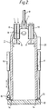
- the container 7 shown in Figure 2 has a casing of generally closed cylindrical shape and which defines a space for containing waste materials.
- the container is designed to be hung from the tether 8 by means of the attachment swivel 11.
- the base or bottom end of the container, opposite the swivel attachment, is closable by a door 12 mounted on a hinge 13.
- Seals 14 are provided between the casing ends and the door.
- a lock mechanism 15 is provided to releasably engage part of the door and there is a ram 16 connected to the lock mechanism to lock or unlock the sealing of the door.
- a second ram 17 is attached to the door in the vicinity of the hinge and is used to close the door.
- a loading port 18 is provided in the upper part of the casing by means of which waste material may be loaded into the container.
- the loading port can be sealed after the container is loaded.
- vent apertures fitted with non-return valves 19.
- the non-return valves provide passages for access into the interior of the container but prevent the exit of material from the container through the vents.
- the container of this example is fabricated from steel, has a mass of about 120 tonnes and an internal capacity of about 2500m 3 .
- This container could, for example, hold about 4000 tonnes of solid waste such as contaminated soil, dredged spoil, flyash and the like.
- the container could hold liquid wastes or slurries (e.g. sewerage sludge of about 5% solids by weight).
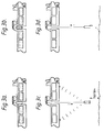
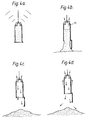
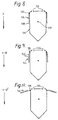
- FIG. 3 a general sequence of operation will be described.
- the ship is loaded with waste material and is taken to a deep water site suitable for waste disposal, Fig. 3(a). Waste material is then loaded into the container whilst the container is held within the moon-pool of the ship, Fig.3 (b).
- the filled container is sealed and is then lowered towards the seabed on the tether.
- the ship is maintained in position by the dynamic positioning system. The position of the container relative to the ship and relative to the seabed is monitored during deployment of the container, Fig. 3(c).
- the container As the container nears the seabed its descent is slowed so that the descent is arrested before it reaches the seabed.
- the container should stop about 10-50m above the seabed.
- the container carries a control pack ( Figure 2, numeral 20) which allows remote operation of the ram 16 to unlock the door of the container.
- a control pack Figure 2, numeral 20
- the waste material drops down to be deposited onto the seabed.
- the load on the tether is thereby reduced and any stretching of the tether will be reduced tending to allow the container to rise somewhat towards the surface.
- the tether is winched in to complete the retrieval of the container into the ships moon-pool, Fig. 3(d).
- FIG. 4 shows in more detail some features of the sequence for waste disposal according to this embodiment of the invention.
- remote signalling can be used to check that the disposal system is ready for operation, Fig. 4(a).
- Figure 4(b) as the door is released the contained material drops as a mass to the seabed under the influence of gravity.
- the one way valves open as the waste drops.
- the cavity formed behind the waste material is flooded with sea water which replaces the expelled material.
- the inside surface of the container may be polished or treated with "non-stick" material in order to assist the smooth expulsion of the waste from the container at the seabed.
- the waste may have added to it various treating agents, e.g. chemical additives such as flocculants and/or stabilizers.
- the treating agents may be added to the waste material as it is loaded into the container, but alternatively there could be inlet ports in the casing of the container for introducing treating agents directly into the material.
- the container will be filled to maximum capacity with waste material, and in other cases the container might be part-filled with sea water and the waste material then added thereto.
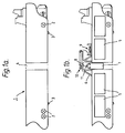
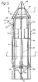
- the vessel comprises a main containment body 101 having a domed upper surface 102 and a somewhat conical lower end 103 which incorporates "clamshell" doors.
- the generally cylindrical body 101 is surrounded by an open framework 104 of struts which include vertical members 105 and horizontal members 106.
- the struts are preferably in the form of metal tubes or pipes coated with ultra high molecular weight polyethylene.
- the struts 105 adopt a generally conical configuration as at 107 and terminate in a lifting/lowering sling 108.
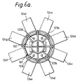
- the vessel also carries eight wing-like members 124a -124h one of which is shown in its opened configuration in Figure 10.
- Each of the wings 124 is attached to the side of the vessel by means of a hinged mechanism such as 125.
- Each of the wings 124 is operated by a hydraulic ram 126 which is linked to its respective wing 124 by an arm 127.
- the hydraulic rams 126 are mounted just above the mid-point of the vessel. With this arrangement, wings 124 are located close to the top of the vessel and well above its centre of mass.
- struts 105 carry water jets 109.
- An altitude sonar 110 is also provided at the lower end of the vessel.
- Stored energy accumulators 128 are carried by the framework 104 in a region below the top surface 102 of containment body 101.
- the upper surface 102 of containment body 101 includes four one-way vents 123a - 123d which permit flow into the vessel but prevent flow from within to without.
- Figure 6b is a plan view corresponding to that of Figure 6a, but with the wing-like members 124a - 124h in their closed configuration.
- FIG. 6c there is shown a plan view of the bottom of the vessel.
- the four "clamshell" doors 129a - 129d are shown closed.
- Figure 6d is a section through the lower part of the vessel, along lines A-A of Figure 5.
- the stored energy accumulators 128a - 128h are attached to the side of the vessel as shown.
- Figure 6e is a section through the upper part of the vessel, along lines B-B of Figure 5.
- the filling port 113 which may be sealed after the vessel is filled, is surrounded by the four one-way vents 123a -123d.
- a marine system for disposal of material on subaqueous ground This comprises a ship, 200, the hull of which includes a moon-pool 201. Over the moon-pool is mounted a gantry 202. On the deck of the ship there is a rope store 203, from which the rope 204 passes through a traction device 205 which allows the rope to run freely and is also able to hold the rope stationary and wind it back in again.
- the rope 204 passes from the traction device 205, via a wheel 206 mounted on top of the gantry 202, to a vessel 207 which is of the type described above with reference to Figures 5 and 6.
- the rope has a design strength sufficient to support the weight of a container and its contents (e.g.
- the vessel may be held in the moon-pool 201 to be filled with waste material contained in the hold 208 of the ship.
- the ship has sensors 209 (e.g. sonar transponders) to measure the water depth below the hull.
- the ship also has a dynamicpositioning system (not shown) in which satellite navigational aids are used to locate the ship accurately, and thrusters 210 are used to maintain the position of the ship over a selected site.
- FIG 8 a schematic alternative embodiment is illustrated which is generally similar in construction and mode of operation to that of Figures 5 and 6; accordingly, only those aspects of this embodiment which differ from those of Figures 5 and 6 will now be described.
- Four wing-like members 134 (two of which are visible in the drawing) are attached to vessel 131 via a hinged mechanism 135.
- Each of the four wing-like members 134 carries, at its lower end, an outwardly extending flange 138.
- One-way vents at the top of the containment body are illustrated diagrammatically at 133.
- the centre of gravity of the containment body 131 is indicated at 139.
- the attachment point for wing-like members 134 is above the level of the centre of gravity 139.
- wing-like members 144 carry a plurality of baffle plates 150.
- baffle plates may be of fixed orientation, or they may be arranged so as to be able to move from a feathered position to an opened position, providing a gentler deceleration than the wing-like members 134.
- the vessel may initially be allowed to descend under "free fall” conditions while tethered to the surface ship through sling 108; the attitude of the vessel and its rate of descent being monitored by sensors (e.g. sonar transponder 110) and modified, where appropriate, by control devices such as motor pumps and water jets (not shown).
- sensors e.g. sonar transponder 110
- control devices such as motor pumps and water jets (not shown).
- the wing-like members (124, 134, 144) are extended outwardly as illustrated in Figures 6 a and 10 to act as water brakes. These significantly decelerate the descent of the vessel, without destabilising it. Deceleration of the downward movement of the vessel can be achieved by applying tension to the rope connected to lifting/lowering sling 8, but in order to give economic operation, without undue strain on the rope, the wings (124, 134, 144) can be used to provide initial decelerating forces and thereby limit the strain on the rope.
- the rope may be coiled in a rope store in such a way that it may be uncoiled freely, but held taut at any time.
- the rope should be sufficiently long so as to allow the vessel to reach the sea bed. Once the vessel has been slowed to a relatively low velocity by wings (124, 134, 144), the rope itself may be used to take the strain until the vessel reaches its predetermined location just above the sea bed. Water jets 109 (see Figure 5) are then operated and serve to blast a depression in the material of the sea bed thereby creating a hollow into which the material contained within the vessel may be deposited. Once the water jets have fulfilled this function, the doors 129a - 129d in the lower end 103 of the containment body are opened, and waste material stored within the containment body (101, 131) leaves the body and settles on the sea bed. The one-way vents (123, 133) permit ingress of sea water which displaces the waste material leaving the body via its lower doors.
- a flocculating agent is advantageously released over the mass of deposited material preferably from a height of about 4.6m (15 feet) above the deposited mass. This assists in ensuring that the waste material is in a cohesive state, and further assists in settling particles derived from the sea bed itself which were dislodged by the water jets in preparation for deposition of the waste material. It would also be possible to treat the waste material chemically before or during the descent of the vessel.
- the vessel After depositing the waste material, the vessel is raised to the surface via the lifting/lowering sling 108 (see Figure 5); during ascent to the surface, the doors at the lower end 103 of the containment body are kept open so that water is able to pass through the interior of the body via one-way vents such as 123a - 123d of Figure 6. This greatly decreases the vessel's resistance to movement, thus facilitating retrieval of the vessel by its mother ship. After retrieval, the vessel may be re-used.
- the means for controlling the wing-like members (124, 134, 144) and the baffles (150) are preferably arranged to ensure that all of the wings open exactly simultaneously and to exactly the same feathering angle and that the baffles do likewise; this maintains stability of the vessel during its descent.
- a vessel with a containment body of capacity 1000 m 3 and weight on air of 177 tons is filled with waste material to a total weight of about 1530 tons. Allowing for hydrostatic displacement, the weight of the full vessel in water is about 370 tons.
- the vessel When the vessel is descending under "free fall” conditions, it reaches a terminal velocity of about 11 metres per second.
- the eight wing-like members which present a total area of about 158 m 2 (1700 square feet) are moved to the open position, the vessel is decelerated to a new terminal velocity of about 6 metres per second, at which speed the rope is used for final deceleration to standstill.
- the vessel After deposition of the waste material, the vessel is drawn back up to the surface, with the one-way vents 123a - 123d and clamshell doors 129a - 129d open, at a speed of about 10 ms -1 (2000 feet per minute).
Landscapes
- Engineering & Computer Science (AREA)
- Chemical & Material Sciences (AREA)
- Combustion & Propulsion (AREA)
- Mechanical Engineering (AREA)
- Ocean & Marine Engineering (AREA)
- Environmental & Geological Engineering (AREA)
- Processing Of Solid Wastes (AREA)
- Underground Or Underwater Handling Of Building Materials (AREA)
- Folding Of Thin Sheet-Like Materials, Special Discharging Devices, And Others (AREA)
- Making Paper Articles (AREA)
- Analysing Materials By The Use Of Radiation (AREA)
- Photoreceptors In Electrophotography (AREA)
- Crystals, And After-Treatments Of Crystals (AREA)
Applications Claiming Priority (2)
| Application Number | Priority Date | Filing Date | Title |
|---|---|---|---|
| GB9108922 | 1991-04-25 | ||
| GB919108922A GB9108922D0 (en) | 1991-04-25 | 1991-04-25 | Apparatus and method for transfering material to subaqueous levels |
Publications (3)
| Publication Number | Publication Date |
|---|---|
| EP0511009A2 EP0511009A2 (en) | 1992-10-28 |
| EP0511009A3 EP0511009A3 (en) | 1993-09-22 |
| EP0511009B1 true EP0511009B1 (en) | 1996-09-11 |
Family
ID=10693929
Family Applications (1)
| Application Number | Title | Priority Date | Filing Date |
|---|---|---|---|
| EP92303726A Expired - Lifetime EP0511009B1 (en) | 1991-04-25 | 1992-04-24 | Apparatus and method for transferring material to subaqueous levels |
Country Status (9)
| Country | Link |
|---|---|
| EP (1) | EP0511009B1 (enExample) |
| AT (1) | ATE142544T1 (enExample) |
| CA (1) | CA2059375C (enExample) |
| DE (1) | DE69213540T2 (enExample) |
| DK (1) | DK0511009T3 (enExample) |
| ES (1) | ES2096032T3 (enExample) |
| GB (1) | GB9108922D0 (enExample) |
| GR (1) | GR3021970T3 (enExample) |
| MX (1) | MX9200425A (enExample) |
Cited By (1)
| Publication number | Priority date | Publication date | Assignee | Title |
|---|---|---|---|---|
| DE102014213760A1 (de) * | 2014-07-15 | 2016-02-18 | Sinn Power Gmbh | Muringsteinschalungsform |
Families Citing this family (2)
| Publication number | Priority date | Publication date | Assignee | Title |
|---|---|---|---|---|
| NO341496B1 (no) | 2014-01-03 | 2017-11-27 | Subsea Logistics As | Undersjøisk lagringsenhet og -system, og fremgangsmåte |
| CN105149315B (zh) * | 2015-10-20 | 2018-03-09 | 四川东方水利装备工程股份有限公司 | 一种水上污物现地处理清污机器人及其水溶处理工艺 |
Family Cites Families (4)
| Publication number | Priority date | Publication date | Assignee | Title |
|---|---|---|---|---|
| DE3224331A1 (de) * | 1982-06-30 | 1984-01-12 | Dyckerhoff & Widmann AG, 8000 München | Verfahren zur deponie von abfallstoffen und behaelter zur anwendung bei diesem verfahren |
| GB2206543B (en) * | 1987-06-25 | 1991-05-22 | Maersk Co Ltd | Waste disposal |
| DE69004983T2 (de) * | 1989-01-23 | 1994-06-23 | Alexander George Copson | Vorrichtung und Verfahren zur Unterwasserablagerung von Abfall. |
| GB2229145A (en) * | 1989-02-10 | 1990-09-19 | Scandinavian Tms Cargo Handlin | Toxic waste disposal to an abyssal plain |
-
1991
- 1991-04-25 GB GB919108922A patent/GB9108922D0/en active Pending
-
1992
- 1992-01-15 CA CA002059375A patent/CA2059375C/en not_active Expired - Fee Related
- 1992-01-31 MX MX9200425A patent/MX9200425A/es unknown
- 1992-04-24 DE DE69213540T patent/DE69213540T2/de not_active Expired - Fee Related
- 1992-04-24 EP EP92303726A patent/EP0511009B1/en not_active Expired - Lifetime
- 1992-04-24 ES ES92303726T patent/ES2096032T3/es not_active Expired - Lifetime
- 1992-04-24 AT AT92303726T patent/ATE142544T1/de not_active IP Right Cessation
- 1992-04-24 DK DK92303726.1T patent/DK0511009T3/da active
-
1996
- 1996-12-11 GR GR960403400T patent/GR3021970T3/el unknown
Cited By (2)
| Publication number | Priority date | Publication date | Assignee | Title |
|---|---|---|---|---|
| DE102014213760A1 (de) * | 2014-07-15 | 2016-02-18 | Sinn Power Gmbh | Muringsteinschalungsform |
| DE102014213760B4 (de) * | 2014-07-15 | 2016-09-22 | Sinn Power Gmbh | Muringsteinschalungsform |
Also Published As
| Publication number | Publication date |
|---|---|
| GB9108922D0 (en) | 1991-06-12 |
| CA2059375C (en) | 2003-07-15 |
| DE69213540D1 (de) | 1996-10-17 |
| ATE142544T1 (de) | 1996-09-15 |
| DE69213540T2 (de) | 1997-03-27 |
| EP0511009A3 (en) | 1993-09-22 |
| MX9200425A (es) | 1993-07-01 |
| EP0511009A2 (en) | 1992-10-28 |
| DK0511009T3 (enExample) | 1997-02-17 |
| GR3021970T3 (en) | 1997-03-31 |
| ES2096032T3 (es) | 1997-03-01 |
| CA2059375A1 (en) | 1992-10-26 |
Similar Documents
| Publication | Publication Date | Title |
|---|---|---|
| US5237946A (en) | Apparatus and method for transferring material to subaqueous levels | |
| JP6693886B2 (ja) | 海底運搬システム | |
| EP2981455B1 (en) | Large subsea package deployment methods and devices | |
| US5115751A (en) | Apparatus and method for subaqueous waste disposal | |
| US3906880A (en) | Oil recovery apparatus for a tanker | |
| WO2001018352A1 (en) | Drilling waste handling | |
| DE3700187A1 (de) | Fluessigabfallentsorgung | |
| JPS6088732A (ja) | 浚渫船 | |
| EP0511009B1 (en) | Apparatus and method for transferring material to subaqueous levels | |
| ES2250859T3 (es) | Procedimiento e instalacion de recuperacion de efluentes en el mar con la ayuda de un deposito de lanzadera. | |
| US8104998B2 (en) | Hydraulic elevation apparatus and method | |
| US3590887A (en) | Port facility ship sewage collection, transportation and disposal system | |
| JPS584133B2 (ja) | 浚渫装置 | |
| US5590979A (en) | Flexible pipe diffuser and method of using the same | |
| JP3008015U (ja) | 泥土の処理装置 | |
| RU2093910C1 (ru) | Способ перезахоронения радиоактивных и токсичных отходов на дне акватории | |
| RU2096842C1 (ru) | Способ перезахоронения радиоактивных и токсичных отходов на дне акватории | |
| JP2673275B2 (ja) | 魚道設備 | |
| JPH1149082A (ja) | 水底投下用土石類運搬船及び土石類の水底投下方法 | |
| JPH0960034A (ja) | 薄層浚渫排送装置 | |
| JP2628429B2 (ja) | ごみ及び廃棄タイヤにより水を汚染することなく埋立地を造成するための方法及びごみを装荷するための装置及び埋立地を造成するためのシステム | |
| JPH0450233Y2 (enExample) | ||
| CA2737319A1 (en) | Hydraulic elevation apparatus and method | |
| GB2206543A (en) | Waste disposal | |
| GB2229145A (en) | Toxic waste disposal to an abyssal plain |
Legal Events
| Date | Code | Title | Description |
|---|---|---|---|
| PUAI | Public reference made under article 153(3) epc to a published international application that has entered the european phase |
Free format text: ORIGINAL CODE: 0009012 |
|
| AK | Designated contracting states |
Kind code of ref document: A2 Designated state(s): AT BE CH DE DK ES FR GB GR IT LI LU MC NL PT SE |
|
| PUAL | Search report despatched |
Free format text: ORIGINAL CODE: 0009013 |
|
| AK | Designated contracting states |
Kind code of ref document: A3 Designated state(s): AT BE CH DE DK ES FR GB GR IT LI LU MC NL PT SE |
|
| 17P | Request for examination filed |
Effective date: 19940609 |
|
| 17Q | First examination report despatched |
Effective date: 19950203 |
|
| GRAH | Despatch of communication of intention to grant a patent |
Free format text: ORIGINAL CODE: EPIDOS IGRA |
|
| GRAH | Despatch of communication of intention to grant a patent |
Free format text: ORIGINAL CODE: EPIDOS IGRA |
|
| GRAA | (expected) grant |
Free format text: ORIGINAL CODE: 0009210 |
|
| AK | Designated contracting states |
Kind code of ref document: B1 Designated state(s): AT BE CH DE DK ES FR GB GR IT LI LU MC NL PT SE |
|
| PG25 | Lapsed in a contracting state [announced via postgrant information from national office to epo] |
Ref country code: CH Effective date: 19960911 Ref country code: AT Effective date: 19960911 Ref country code: LI Effective date: 19960911 |
|
| REF | Corresponds to: |
Ref document number: 142544 Country of ref document: AT Date of ref document: 19960915 Kind code of ref document: T |
|
| REF | Corresponds to: |
Ref document number: 69213540 Country of ref document: DE Date of ref document: 19961017 |
|
| ITF | It: translation for a ep patent filed | ||
| ET | Fr: translation filed | ||
| REG | Reference to a national code |
Ref country code: DK Ref legal event code: T3 |
|
| REG | Reference to a national code |
Ref country code: GR Ref legal event code: FG4A Free format text: 3021970 |
|
| REG | Reference to a national code |
Ref country code: ES Ref legal event code: FG2A Ref document number: 2096032 Country of ref document: ES Kind code of ref document: T3 |
|
| REG | Reference to a national code |
Ref country code: CH Ref legal event code: PL |
|
| REG | Reference to a national code |
Ref country code: PT Ref legal event code: SC4A Free format text: AVAILABILITY OF NATIONAL TRANSLATION Effective date: 19961211 |
|
| PLBE | No opposition filed within time limit |
Free format text: ORIGINAL CODE: 0009261 |
|
| STAA | Information on the status of an ep patent application or granted ep patent |
Free format text: STATUS: NO OPPOSITION FILED WITHIN TIME LIMIT |
|
| 26N | No opposition filed | ||
| REG | Reference to a national code |
Ref country code: GB Ref legal event code: IF02 |
|
| PGFP | Annual fee paid to national office [announced via postgrant information from national office to epo] |
Ref country code: DE Payment date: 20070430 Year of fee payment: 16 |
|
| PGFP | Annual fee paid to national office [announced via postgrant information from national office to epo] |
Ref country code: PT Payment date: 20080324 Year of fee payment: 17 |
|
| PGFP | Annual fee paid to national office [announced via postgrant information from national office to epo] |
Ref country code: LU Payment date: 20080416 Year of fee payment: 17 |
|
| PGFP | Annual fee paid to national office [announced via postgrant information from national office to epo] |
Ref country code: MC Payment date: 20080417 Year of fee payment: 17 Ref country code: BE Payment date: 20080416 Year of fee payment: 17 Ref country code: IT Payment date: 20080415 Year of fee payment: 17 |
|
| PGFP | Annual fee paid to national office [announced via postgrant information from national office to epo] |
Ref country code: SE Payment date: 20080425 Year of fee payment: 17 Ref country code: NL Payment date: 20080428 Year of fee payment: 17 |
|
| PG25 | Lapsed in a contracting state [announced via postgrant information from national office to epo] |
Ref country code: DE Free format text: LAPSE BECAUSE OF NON-PAYMENT OF DUE FEES Effective date: 20081101 |
|
| PGFP | Annual fee paid to national office [announced via postgrant information from national office to epo] |
Ref country code: ES Payment date: 20090429 Year of fee payment: 18 Ref country code: DK Payment date: 20090427 Year of fee payment: 18 |
|
| BERE | Be: lapsed |
Owner name: *COPSON ALEX GEORGE Effective date: 20090430 Owner name: *KONGSLI CHRISTIAN Effective date: 20090430 |
|
| REG | Reference to a national code |
Ref country code: PT Ref legal event code: MM4A Free format text: LAPSE DUE TO NON-PAYMENT OF FEES Effective date: 20091026 |
|
| PGFP | Annual fee paid to national office [announced via postgrant information from national office to epo] |
Ref country code: GR Payment date: 20090429 Year of fee payment: 18 |
|
| EUG | Se: european patent has lapsed | ||
| NLV4 | Nl: lapsed or anulled due to non-payment of the annual fee |
Effective date: 20091101 |
|
| REG | Reference to a national code |
Ref country code: FR Ref legal event code: ST Effective date: 20091231 |
|
| PG25 | Lapsed in a contracting state [announced via postgrant information from national office to epo] |
Ref country code: NL Free format text: LAPSE BECAUSE OF NON-PAYMENT OF DUE FEES Effective date: 20091101 |
|
| PG25 | Lapsed in a contracting state [announced via postgrant information from national office to epo] |
Ref country code: PT Free format text: LAPSE BECAUSE OF NON-PAYMENT OF DUE FEES Effective date: 20091026 |
|
| PG25 | Lapsed in a contracting state [announced via postgrant information from national office to epo] |
Ref country code: MC Free format text: LAPSE BECAUSE OF NON-PAYMENT OF DUE FEES Effective date: 20090430 Ref country code: FR Free format text: LAPSE BECAUSE OF NON-PAYMENT OF DUE FEES Effective date: 20091222 |
|
| PGFP | Annual fee paid to national office [announced via postgrant information from national office to epo] |
Ref country code: FR Payment date: 20080425 Year of fee payment: 17 |
|
| PG25 | Lapsed in a contracting state [announced via postgrant information from national office to epo] |
Ref country code: BE Free format text: LAPSE BECAUSE OF NON-PAYMENT OF DUE FEES Effective date: 20090430 |
|
| PGFP | Annual fee paid to national office [announced via postgrant information from national office to epo] |
Ref country code: GB Payment date: 20100426 Year of fee payment: 19 |
|
| REG | Reference to a national code |
Ref country code: DK Ref legal event code: EBP |
|
| PG25 | Lapsed in a contracting state [announced via postgrant information from national office to epo] |
Ref country code: IT Free format text: LAPSE BECAUSE OF NON-PAYMENT OF DUE FEES Effective date: 20090424 Ref country code: GR Free format text: LAPSE BECAUSE OF NON-PAYMENT OF DUE FEES Effective date: 20101103 |
|
| PG25 | Lapsed in a contracting state [announced via postgrant information from national office to epo] |
Ref country code: LU Free format text: LAPSE BECAUSE OF NON-PAYMENT OF DUE FEES Effective date: 20090424 Ref country code: DK Free format text: LAPSE BECAUSE OF NON-PAYMENT OF DUE FEES Effective date: 20100503 |
|
| PG25 | Lapsed in a contracting state [announced via postgrant information from national office to epo] |
Ref country code: SE Free format text: LAPSE BECAUSE OF NON-PAYMENT OF DUE FEES Effective date: 20090425 |
|
| REG | Reference to a national code |
Ref country code: ES Ref legal event code: FD2A Effective date: 20110708 |
|
| PG25 | Lapsed in a contracting state [announced via postgrant information from national office to epo] |
Ref country code: ES Free format text: LAPSE BECAUSE OF NON-PAYMENT OF DUE FEES Effective date: 20110628 |
|
| PG25 | Lapsed in a contracting state [announced via postgrant information from national office to epo] |
Ref country code: ES Free format text: LAPSE BECAUSE OF NON-PAYMENT OF DUE FEES Effective date: 20100425 |
|
| GBPC | Gb: european patent ceased through non-payment of renewal fee |
Effective date: 20110424 |
|
| PG25 | Lapsed in a contracting state [announced via postgrant information from national office to epo] |
Ref country code: GB Free format text: LAPSE BECAUSE OF NON-PAYMENT OF DUE FEES Effective date: 20110424 |