EP0510702A1 - Appareils de formation de feuilles en matière plastique sous haute pression - Google Patents
Appareils de formation de feuilles en matière plastique sous haute pression Download PDFInfo
- Publication number
- EP0510702A1 EP0510702A1 EP92107103A EP92107103A EP0510702A1 EP 0510702 A1 EP0510702 A1 EP 0510702A1 EP 92107103 A EP92107103 A EP 92107103A EP 92107103 A EP92107103 A EP 92107103A EP 0510702 A1 EP0510702 A1 EP 0510702A1
- Authority
- EP
- European Patent Office
- Prior art keywords
- film
- pallet
- tool
- station
- deformed
- Prior art date
- Legal status (The legal status is an assumption and is not a legal conclusion. Google has not performed a legal analysis and makes no representation as to the accuracy of the status listed.)
- Withdrawn
Links
Images


Classifications
-
- B—PERFORMING OPERATIONS; TRANSPORTING
- B29—WORKING OF PLASTICS; WORKING OF SUBSTANCES IN A PLASTIC STATE IN GENERAL
- B29C—SHAPING OR JOINING OF PLASTICS; SHAPING OF MATERIAL IN A PLASTIC STATE, NOT OTHERWISE PROVIDED FOR; AFTER-TREATMENT OF THE SHAPED PRODUCTS, e.g. REPAIRING
- B29C51/00—Shaping by thermoforming, i.e. shaping sheets or sheet like preforms after heating, e.g. shaping sheets in matched moulds or by deep-drawing; Apparatus therefor
- B29C51/26—Component parts, details or accessories; Auxiliary operations
- B29C51/42—Heating or cooling
- B29C51/421—Heating or cooling of preforms, specially adapted for thermoforming
-
- B—PERFORMING OPERATIONS; TRANSPORTING
- B29—WORKING OF PLASTICS; WORKING OF SUBSTANCES IN A PLASTIC STATE IN GENERAL
- B29C—SHAPING OR JOINING OF PLASTICS; SHAPING OF MATERIAL IN A PLASTIC STATE, NOT OTHERWISE PROVIDED FOR; AFTER-TREATMENT OF THE SHAPED PRODUCTS, e.g. REPAIRING
- B29C51/00—Shaping by thermoforming, i.e. shaping sheets or sheet like preforms after heating, e.g. shaping sheets in matched moulds or by deep-drawing; Apparatus therefor
- B29C51/10—Forming by pressure difference, e.g. vacuum
-
- B—PERFORMING OPERATIONS; TRANSPORTING
- B29—WORKING OF PLASTICS; WORKING OF SUBSTANCES IN A PLASTIC STATE IN GENERAL
- B29C—SHAPING OR JOINING OF PLASTICS; SHAPING OF MATERIAL IN A PLASTIC STATE, NOT OTHERWISE PROVIDED FOR; AFTER-TREATMENT OF THE SHAPED PRODUCTS, e.g. REPAIRING
- B29C51/00—Shaping by thermoforming, i.e. shaping sheets or sheet like preforms after heating, e.g. shaping sheets in matched moulds or by deep-drawing; Apparatus therefor
- B29C51/14—Shaping by thermoforming, i.e. shaping sheets or sheet like preforms after heating, e.g. shaping sheets in matched moulds or by deep-drawing; Apparatus therefor using multilayered preforms or sheets
-
- B—PERFORMING OPERATIONS; TRANSPORTING
- B29—WORKING OF PLASTICS; WORKING OF SUBSTANCES IN A PLASTIC STATE IN GENERAL
- B29C—SHAPING OR JOINING OF PLASTICS; SHAPING OF MATERIAL IN A PLASTIC STATE, NOT OTHERWISE PROVIDED FOR; AFTER-TREATMENT OF THE SHAPED PRODUCTS, e.g. REPAIRING
- B29C51/00—Shaping by thermoforming, i.e. shaping sheets or sheet like preforms after heating, e.g. shaping sheets in matched moulds or by deep-drawing; Apparatus therefor
- B29C51/18—Thermoforming apparatus
- B29C51/20—Thermoforming apparatus having movable moulds or mould parts
- B29C51/24—Thermoforming apparatus having movable moulds or mould parts mounted on movable endless supports
-
- B—PERFORMING OPERATIONS; TRANSPORTING
- B29—WORKING OF PLASTICS; WORKING OF SUBSTANCES IN A PLASTIC STATE IN GENERAL
- B29C—SHAPING OR JOINING OF PLASTICS; SHAPING OF MATERIAL IN A PLASTIC STATE, NOT OTHERWISE PROVIDED FOR; AFTER-TREATMENT OF THE SHAPED PRODUCTS, e.g. REPAIRING
- B29C51/00—Shaping by thermoforming, i.e. shaping sheets or sheet like preforms after heating, e.g. shaping sheets in matched moulds or by deep-drawing; Apparatus therefor
- B29C51/26—Component parts, details or accessories; Auxiliary operations
- B29C51/261—Handling means, e.g. transfer means, feeding means
-
- B—PERFORMING OPERATIONS; TRANSPORTING
- B29—WORKING OF PLASTICS; WORKING OF SUBSTANCES IN A PLASTIC STATE IN GENERAL
- B29C—SHAPING OR JOINING OF PLASTICS; SHAPING OF MATERIAL IN A PLASTIC STATE, NOT OTHERWISE PROVIDED FOR; AFTER-TREATMENT OF THE SHAPED PRODUCTS, e.g. REPAIRING
- B29C35/00—Heating, cooling or curing, e.g. crosslinking or vulcanising; Apparatus therefor
- B29C35/02—Heating or curing, e.g. crosslinking or vulcanizing during moulding, e.g. in a mould
- B29C35/08—Heating or curing, e.g. crosslinking or vulcanizing during moulding, e.g. in a mould by wave energy or particle radiation
- B29C35/0805—Heating or curing, e.g. crosslinking or vulcanizing during moulding, e.g. in a mould by wave energy or particle radiation using electromagnetic radiation
- B29C2035/0822—Heating or curing, e.g. crosslinking or vulcanizing during moulding, e.g. in a mould by wave energy or particle radiation using electromagnetic radiation using IR radiation
-
- B—PERFORMING OPERATIONS; TRANSPORTING
- B29—WORKING OF PLASTICS; WORKING OF SUBSTANCES IN A PLASTIC STATE IN GENERAL
- B29C—SHAPING OR JOINING OF PLASTICS; SHAPING OF MATERIAL IN A PLASTIC STATE, NOT OTHERWISE PROVIDED FOR; AFTER-TREATMENT OF THE SHAPED PRODUCTS, e.g. REPAIRING
- B29C2793/00—Shaping techniques involving a cutting or machining operation
- B29C2793/0045—Perforating
-
- B—PERFORMING OPERATIONS; TRANSPORTING
- B29—WORKING OF PLASTICS; WORKING OF SUBSTANCES IN A PLASTIC STATE IN GENERAL
- B29C—SHAPING OR JOINING OF PLASTICS; SHAPING OF MATERIAL IN A PLASTIC STATE, NOT OTHERWISE PROVIDED FOR; AFTER-TREATMENT OF THE SHAPED PRODUCTS, e.g. REPAIRING
- B29C2793/00—Shaping techniques involving a cutting or machining operation
- B29C2793/009—Shaping techniques involving a cutting or machining operation after shaping
-
- B—PERFORMING OPERATIONS; TRANSPORTING
- B29—WORKING OF PLASTICS; WORKING OF SUBSTANCES IN A PLASTIC STATE IN GENERAL
- B29C—SHAPING OR JOINING OF PLASTICS; SHAPING OF MATERIAL IN A PLASTIC STATE, NOT OTHERWISE PROVIDED FOR; AFTER-TREATMENT OF THE SHAPED PRODUCTS, e.g. REPAIRING
- B29C51/00—Shaping by thermoforming, i.e. shaping sheets or sheet like preforms after heating, e.g. shaping sheets in matched moulds or by deep-drawing; Apparatus therefor
- B29C51/26—Component parts, details or accessories; Auxiliary operations
- B29C51/261—Handling means, e.g. transfer means, feeding means
- B29C51/262—Clamping means for the sheets, e.g. clamping frames
Definitions
- the invention relates to a device for the high-pressure deformation of plastic films, the films being acted upon by a fluid pressure medium below the plastic softening temperature and deformed isostatically under a pressure medium pressure greater than 20 bar.
- the devices mentioned in this document for carrying out the isostatic high-pressure shaping of plastic films provide a molding tool which has to be loaded with the film to be deformed by an operator and must be controlled in each individual working step. Automated production is not possible with the known devices.
- document US-A-4,842,668 discloses a process for producing laminated plastic products.
- a stack of superimposed layers of thermosetting material for example paper sheets impregnated with synthetic resin
- These transport devices are successively passed through a preheating furnace, through a thermoforming press and a separating station, in which the molded laminated plastic product, for example a tray for canteens and the like, is detached from the transport device.
- the plastic product goes into a collecting container and the transport devices are returned to the starting point of the process in order to pick up stacks again from the material to be deformed.
- the object of the invention is to provide an automated device for the high-pressure deformation of plastic films, which ensures high precision in the 1/10 mm range and cycle times of more than 20 film deformations per minute when films with a layer thickness between 0.05 and 2 .00 mm below the plastic softening temperature with a fluid pressure medium and isostatically deformed under a pressure medium pressure greater than 20 bar.
- the new, automated device should additionally be equipped with at least one punching device.
- the device according to the invention enables the precise and automated high-pressure deformation of plastic foils in order to produce drawn parts which have permanent deformation.
- the starting foils used are typically flat and have a layer thickness between 0.05 and 2.0 mm. These starting foils are preferably provided with motifs, illustrations, symbols and / or other markings which are printed on or applied as a coating.
- the peculiarity of the high-pressure deformation mentioned here is precisely that a deformation in the area of the print or the coating can be carried out without the respective image or motif being distorted.
- the device according to the invention ensures automated deformation according to a predetermined contour exactly at the desired location without distortion of an existing image or motif in automated form at high cycle times, of at least 20 deformation steps per minute.
- An exemplary embodiment of a device according to the invention creates cycle times of 30 deformation steps per minute.
- the drawn parts produced with the device according to the invention are used in particular in motor vehicles and form, for example, housing parts, illuminated sign or instrument covers, illuminated pushbuttons or switch buttons, heating panels, dashboard sections or rear light lenses or the cover layers of such plastic parts and typically have differently colored and / or or transparent wall sections. If necessary, the drawn parts produced with the device according to the invention can additionally be reinforced with additional plastic.
- each pallet can preferably consist essentially of a flat, frame-like, rectangular sheet metal plate, on which at least one recess is formed, and which rests on the opposite narrow sides of a pallet holder and is fixed there with a releasable fastening means.
- Fasteners such as bayonet locks, which can be released quickly and easily are particularly suitable as fasteners because, when a shape is changed, all the pallets of the device generally have to be exchanged and adapted.
- the two pallet holders arranged opposite and at a distance from one another are each attached to a circulating chain, which are guided parallel and at a distance from one another.
- the chains are preferably driven by a stepping gear and a three-phase motor.
- Each pallet has at least one recess which is covered by the film to be deformed.
- the pallet itself is not clamped into the mold, but is centered by fitting matching sections on the outer circumference of the mold against matching sections on the inner circumference of the pallet recess with respect to the mold and being arranged to within a few 1/10 millimeters with respect to the mold.
- a pallet can have one or more cutouts for the simultaneous deformation of one or more film sections.
- the pallets can be made of sheet steel, which is angled in the region of the two longitudinal side edge sections running transversely to the conveying direction in order to ensure greater stability.
- At least two centering pins protrude from the top of the metal frame of each pallet, which pins fit into openings or recesses in the one to be deformed Intervene film to ensure a defined arrangement of the film in relation to the pallet.
- the film can be arranged on the pallet without displacement.
- each film to be deformed on each pallet takes place in the lay-up station.
- the strand of pallets which is moved forward step by step, is briefly stopped and a film is placed on the pallet in the lay-up station. The film can be removed by hand.
- an automated lay-up station which has a magazine containing a large number of foils and a rotatably and pivotably arranged device provided with suction cups. This device packs the film in the magazine at the end of each work cycle, removes this film from the magazine and places it on the pallet in the lay-up station. A precise fit is ensured with the help of the centering pins on the pallet and corresponding openings / recesses on the film.
- the device according to the invention has a heating station which is arranged along the pallet strand path between the laying station and the forming station.
- the films are introduced into the forming station with a film temperature of approximately 30 to 40 ° C .; in individual cases, however, film temperatures of, for example, 60 ° C. and more can also be provided.
- a heating station is preferably provided, which can accommodate several pallets with one film each to be deformed per work cycle.
- a heating station that comprises three pallets has proven itself.
- the desired film temperature can be set with a fluctuation range of approximately 1 to 2 ° C.
- the heating station preferably has several, for example three, heating fields, which in turn are each made up of a number of infrared surface radiators.
- Each heating field has at least some independently controllable infrared area radiators.
- the peripheral infrared surface emitters can each be controlled independently.
- the heating station has at least one pilot radiator, the surface temperature of which can be kept within narrow limits with the aid of a thermocouple. This pilot emitter delivers control impulses to control the independently controllable infrared area emitters.
- These heating fields are preferably attached to a heating box which is arranged above the path of movement of the pallet strand.
- the arrangement of the heating box with respect to the path of movement of the pallet strand can be changed several times.
- the vertical distance of the heating box with respect to the path of movement of the pallet strand can be changed. This makes it easier to set a certain film temperature.
- the heating box can be brought from an arrangement above the path of movement of the pallet strand into a laterally offset position. In this heating box rest position, the heating fields can be brought to the desired temperature.
- a reflector can be arranged at a distance from the heating fields in this heating box rest position. As a result, the energy consumption in the heating box rest position is reduced.
- This forming station preferably has a column frame with a number of vertically aligned columns.
- the upper molding table is essentially fixed in place on these columns and can be adjusted to a small extent in the vertical direction for adjustment purposes.
- the lower molding table is slidably guided along these columns.
- the lower molding table is adjusted with the aid of a drive which has a geared brake motor, a crank drive, a connecting rod with a vertically adjustable connecting rod bearing and a double toggle lever arrangement.
- This double toggle arrangement has three arms per simple toggle arrangement on, which are mounted on a common toggle lever shaft.
- the geared brake motor is exactly in the closed position, that is in the upper dead position of the adjustment of the lower mold table and in the release position, that can be stopped in the lower dead position of the adjustment of the lower mold table.
- Each form table is expediently essentially square in plan view and has expanded corner regions. Four columns are provided which are guided through holes which are cut out in the four corner areas of each molding table.
- the adjustment of the lower molding table via a toggle lever arrangement and a crank drive ensures a sinusoidal drive, so that the lower molding table gradually assumes the top dead center (closed position) and the bottom dead center (release position) of its adjustment movement. Very considerable form-locking forces are obtained with little noise.
- the vertical adjustment of the upper molding table is preferably carried out with the help of a chain synchronism along a threaded connection.
- the upper end sections of each column are provided with an externally threaded section.
- the upper molding table is essentially square in plan view, and a hole is recessed in each corner region, into which a bushing is rotatably inserted, which is provided with a suitable internal thread section.
- Each socket is also provided with a ring gear.
- Each bushing can be rotated to the same extent via a driven chain, thus raising or lowering the upper mold table.
- the base plate is attached to the molding table, thermal insulation being inserted between the molding table and the base plate.
- the tool is attached to the base plate, for example screwed tight.
- the springs When the springs are compressed, the top of the nut mold is essentially aligned with the contour and / or with the bottom of a mold cavity on the tool. If the entire molding tool is opened again after the high-pressure deformation, the springs raise the nut mold and the nut mold releases the deformed film from the tool.
- the spring-loaded nut shape facilitates the demolding of the deformed part.
- an outwardly open, circumferential step is formed on the top of the spring-loaded nut shape, the dimensions of which are adapted to the recess within each pallet.
- the pallet conveyor transports the pallet with the film to be deformed to a position above the mother mold.
- the nut shape is also adjusted vertically upward, and the raised peripheral edge section on the top of the nut shape slides into the recess within the pallet.
- the pallet is centered and the film to be deformed takes up exactly the position for the high-pressure deformation with respect to the mold.
- the film to be deformed is positioned with an accuracy of a few 1/10 millimeters.
- the other, suitable mold half is fastened to the upper mold table, in which a mold cavity is recessed, into which the fluid pressure medium can be introduced.
- This other tool half has a circumferential lower edge which is provided with a sealant, for example with an O-ring.
- the nut mold surrounded by the pallet comes to rest against the circumferential edge of the upper mold half.
- the springs carrying the mother mold are gradually compressed and the entire mold is closed, the sealant ensuring a pressure-tight seal.
- the fluid pressure medium is then introduced into the mold cavity, acts on the film and forms it on the contour of the tool.
- the film material is acted upon directly and directly with the fluid pressure medium.
- Compressed air is particularly and preferably considered as the fluid pressure medium.
- the film is adapted to the contour of the tool and the forming process is finished.
- it may be advisable to delay the build-up of pressure by throttling the pressure medium.
- the complete deformation of the entire film can take a little longer. In these cases, too, the deformation is completed within a period of less than 2 seconds.
- the pressure medium supply is stopped, the mold cavity is relieved, and the lower mold table is lowered again.
- the springs that support the mother frame raise the mother frame, removing the deformed film from the tool.
- the pallet is released from the mother mold.
- the pallet conveyor drive is started again and the pallet with the deformed film is transported further and comes out of the forming station.
- the deformed film is released from the pallet holding it and picked up in a collecting device.
- the pallet strand is guided over deflection rollers, and the film separates from the pallet under the effect of gravity and falls into a collecting container.
- the film can be removed from the pallet by hand and placed in a collecting container.
- the film can be detached from the pallet with the aid of compressed air and / or with the aid of suction devices and placed in the collecting container.
- a removal station is preferably provided, which has a stamp that can be moved back and forth and a stacking channel arranged at a distance from it.
- the pallet strand is guided over a deflection roller and continues to be guided in a substantially vertical direction through a gap between the punch and the stacking trough. With each movement of the stamp, a film is pressed out of the pallet and pushed into the stacking channel.
- the stacking trough is preferably arranged to rise slightly in relation to a horizontal direction in order to prevent the foils from falling over.
- this pallet is again guided along a pallet transport path into the lay-up station in order to place a film to be deformed there again on the pallet.
- a fluid pressure medium is applied to the film, which has a pressure medium pressure of at least 20 bar.
- Compressed air is preferably used as the fluid pressure medium.
- compressed air with a pressure between about 60 and 300 bar is used.
- a compressed air generator is assigned to the device according to the invention, which is equipped with a multi-stage compressor in order to generate compressed air at a pressure of approximately 330 bar.
- the compressed air is passed through a condensation dryer to separate water.
- the dried one Compressed air is collected in a storage bottle.
- the compressed air flows from the storage bottle via a line into the mold.
- One or more pressure reducers are used in this compressed air line.
- the compressors are always put into operation automatically when the pressure in the storage bottle has decreased by a certain amount.
- the drive motor and the various deflection rollers for the pallet train as well as the components of the stations explained above are attached to a frame that rests on a foundation via metal feet.
- the vibrating metal feet are equipped with vibration-damping rubber elements and have adjustment spindles for precise adjustment of the parallelism of the units.
- the vibrating metal feet dampen a large part of the shock-like vibrations that occur during the operation of the forming station.
- the frame is clad in the usual way, and access is via doors that are secured with limit switches.
- the device according to the invention can additionally be equipped with a punching station which is arranged between the forming station and the removal station. If a punching station is provided, the pallet strand is extended accordingly and an additional number of pallets is provided.
- the punching station can have separate units, which are designed on the one hand as a punch punch and on the other hand as a diarrhea punch.
- a combined punching unit is preferably provided, which is equipped both with a hole punching tool and with a diarrhea cut punching tool.
- Such a combined punching unit can preferably take up two pallets, each with a deformed film, per work cycle and has a lower table guided on a column frame and driven by an electric motor via a double toggle lever arrangement.
- This is assigned an upper punching table, which can be adjusted vertically to a small extent with the help of a chain synchronism, like that for the upper molding table of the molding station is described.
- the cutting tools are preferably designed with slide-in technology in order to enable a quick tool change.
- the cutting tools are attached to the under table.
- Matching abutments or counterparts are attached to the upper table. Terminal strips are preferably used to fasten these tool components. In the locked position, these terminal strips are pre-tensioned via disc springs.
- a number of pneumatically actuated piston / cylinder arrangements are provided, which raise the terminal block via a stamp and bring it into a tool change position. Even if there is a loss of pressure, there can be no unintentional loosening of the terminal strips and consequent adjustment of the tools.
- the centering of the pallet, which holds the film that has already been deformed and to be punched, on a base plate of the punching tool takes place in the same way as that described above for centering the pallet on the mother mold of the molding tool.
- the lower table is additionally provided with a pneumatic ejector, which conveys the punched-out drawn part through the die into a stacking cage which is inserted into the upper table.
- the punched molded parts are finally removed by hand.
- the remaining leadframe remains on the pallet and is finally removed in the removal station.
- a drive via a geared motor, crank drive and double toggle lever arrangement is preferably provided, which delivers a punching force of 0.3 mega newtons and more, for example 0.4 mega newtons.
- the device according to the invention has a machine frame 1 which rests on oscillating feet 2 which are supported on a foundation.
- a placement station 20, a heating station 40, a forming station 50 and a removal station 160 are each arranged on the machine frame 1.
- an optionally provided punching station 120 can be provided, as shown in FIG. 3.
- the foils 3 to be deformed are put on by hand and the deformed foils 4 are removed automatically under the action of gravity.
- a large number of pallets 5 are arranged in a closed, practically endless pallet strand 6.
- Each pallet 5 is used to transport a film 3 to be deformed or a deformed film 4 through selected workstations of the device.
- Each pallet 5 consists of a rectangular, frame-like sheet metal plate, on which at least one recess 7 is formed, which is covered by the film 3 to be deformed.
- Two centering pins 8 protrude from the pallet 5, which engage in suitably arranged recesses in the film 3 to be deformed, in order to ensure a precisely fitting arrangement of the film 3 with respect to the pallet 5.
- each pallet 5 is held by a pallet holder 9, which in turn is articulated on chain links of a revolving chain 10.
- a film 3 to be deformed is arranged on each pallet 5 with a precise fit.
- the film 3 to be deformed is provided with an optionally multi-colored print or other coating which is adapted to the intended use of the drawn part to be produced.
- the foils 3 can be applied by hand, as indicated in FIG. 1.
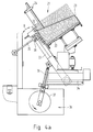
- an automated lay-up station 20 is preferably provided, which is shown schematically in FIGS. 4a and 4b.
- the essential components of the support station 20 include an adjustable magazine 21, which contains a plurality of foils 3 in a parallel arrangement, two parallel, spaced and synchronously guided support arms 30, which rotatably hold a suction pipe 31 to which a number of suction cups 32 are adjustably attached are, as well as the drive 36 for at least one support arm 30.
- the suction pipe 31 is rotated back and forth in sections so that the suction cups 32 perform a pivoting movement according to arrow "B" (see FIG. 4a).
- the magazine 21 has a height-adjustable magazine bottom 22 and side-adjustable magazine side walls 23.
- the magazine base 22 is aligned in an increasing manner, preferably increasing at a 30 ° angle with respect to the horizontal. With the aid of a height-adjustable retaining bar 24 on the top of the magazine and the side-adjustable magazine side walls 23, the magazine 21 can be set up to the current film format.
- the suction pipe 31 is connected via a controllable valve device 33 to a vacuum source (not shown). The position of the suction cups 32 can easily be adapted to the current film format.
- the valve device 33 applies suction to the suction devices 32 or ventilates them in accordance with the working steps of a lay-on cycle.
- the suckers 32 pack the film 3, which is respectively terminal in the magazine 21, transport it to the pallet 5 located in the lay-up station 20 and place it thereon.
- one end of the support arm 30 is guided in a guide gap 34 and the other end is held by a rocker arm 35.
- the swivel drive 36 has a crank drive 37 and a connecting rod 38.
- the crank drive 37 is driven by a motor (not shown) and carries out one revolution per work cycle. Limit switches, adjusting screws and sensors are also provided for monitoring the operation.
- the film 3 is heated to a defined temperature, which is typically in the range between 30 and 40 ° C, but can also be 60 ° C and more in individual cases.
- the film 3 deposited on a pallet 5 is heated in the heating station 40.
- FIG. 5 schematically shows the structure of a heating station 40.
- the heating station 40 has three heating fields 41, 41 ′ and 41 ′′, which are arranged at a distance above the path of movement of the pallet strand 6.
- Each heating field 41, 41 ', 41'' has a number of infrared area radiators 42, some of which can be controlled independently.
- the peripheral infrared area radiators 42 ' can preferably be controlled independently.
- a pilot radiator 43 is with sensors equipped to record the ambient temperature and the surface temperature. The surface temperature of the pilot radiator 43 can be kept constant within narrow limits.
- the pilot radiator 43 supplies signals for controlling the independently controllable IR surface radiators 42 '.
- the heating fields 41, 41 'and 41'' are preferably attached to a heating box 44 which is height-adjustable with respect to the movement path of the pallet strand 6 and can be moved laterally next to this movement path.
- a reflector (not shown) is additionally provided, which is arranged at a distance from the IR surface radiators 42, 42 '.
- the film 3 heated to the intended film temperature reaches the forming station 50 and is subjected to a fluid pressure medium there in order to carry out the isostatic high-pressure deformation.
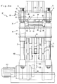
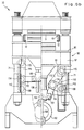
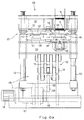
- a preferred molding station 50 is shown with FIGS. 6a, 6b and 6c.
- the essential components of the molding station 50 include a press 70, a drive 100 for the press 70 and a molding tool 51, on which the deformation is carried out.
- the press 70 has an upper molding table 80, a lower molding table 90 and a column frame with four vertically aligned columns 71, on which the molding tables 80, 90 are guided.
- Each column 71 is provided with an externally threaded portion 72 at the upper end portion.
- each shaping table 80, 90 is essentially square (see FIG.
- Each molding table 80, 90 has a table top 81 and 91, which is supported on a support frame 82, 92, which in turn has a plurality of support bars 83, 93.
- a heavy, solid construction is provided for the press 70 which can absorb and / or exert considerable forces.
- An exemplary press - with a molding area of approx. 240 cm2 - is designed for a maximum molding pressure of approx. 300 bar and generates a mold closing force of at least 300 megabytes with the drive to be explained.
- the upper molding table 80 is arranged essentially stationary, but can be adjusted to a small extent in the vertical direction for adjustment purposes. A chain synchronism is provided for this.
- a rotatably held bushing 85 is inserted, which is provided on its inner circumference with an internally threaded section 86.
- a ring gear 87 is attached to each bush 85.
- a motorized chain 18 successively engages each ring gear 87 and causes each bushing 85 to rotate by the same amount, causing the upper forming table 80 to move vertically along the threaded portions 72/86.
- the lower molding table 90 is vertically adjustable along the columns 71.
- the structure of the drive 100 for adjusting the lower molding table 90 can be seen in particular from FIGS. 6b and 6c; here the left partial view of FIG. 6b shows the upper dead position of the mold table adjustment (closed position) and the right partial view of FIG. 6b shows the lower dead position of the mold table adjustment (release position).
- This drive 100 includes an electrically operated spur gear transmission brake motor 101, which drives a crank drive 102.
- the crank 103 acts via a connecting rod 104 on a displaceable connecting rod bearing 105 which is guided on guide rods 106 so as to be displaceable in the vertical direction.
- a double toggle lever arrangement 110 has three articulated arms 111, 112 and 113 which are all mounted on the common toggle lever shaft 114.
- the first arm 111 extends between the toggle lever shaft 114 and a shaft 107 on the connecting rod bearing 105.
- the second arm 112 extends between the toggle lever shaft 114 and a support shaft 108 which is supported on the press frame.
- the third arm 113 extends between the toggle shaft 114 and one Shaft 115, which is supported on the support bars 93 of the lifting frame 92 of the lower molding table 90.
- the first arm 111 extends essentially horizontally and the second and third arms 112 and 113 in the vertical direction parallel to the columns 71 of the column frame - in the upper dead position of the crank movement.
- the spur gear transmission brake motor can be stopped exactly in this position, which corresponds to the closed position of the lower molding table 90.
- the drive 100 can exert and / or absorb a particularly high molding pressure. Due to the sinusoidal adjustment via crank drive 102 and double toggle lever arrangement 110, the drive 100 operates very quietly and the lower molding table 90 gradually assumes its upper or lower end position or dead position.
- the lower molding table 90 is raised until it has reached an upper dead center and assumes its closed position, or is lowered until the lower molding table 90 has reached its lower dead center and assumes a release position.
- the transmission brake motor 101 can be stopped exactly in these respective end positions.
- a chain protection frame 12 is guided, which shields each chain 10, which hold and transport the plurality of pallets 5.
- pairs of angle profiles 99, 89 are arranged, each of which delimit a guide groove into which a supporting element 53, 61 of the upper and lower tool halves 52, 60 can be inserted.
- One locking device (not shown) secures the inserted tool half 52, 60 in the arrangement provided. The resulting slide-in technique allows the tool halves 52, 60 to be changed quickly.
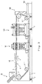
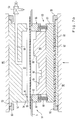
- FIG. 7a shows a molding tool 51 in the open state
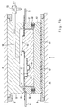
- FIG. 7b shows the molding tool 51 in the closed state after an isostatic high-pressure deformation has been carried out.
- the molding tool 51 essentially consists of an upper part 52 and a lower tool half 60.
- the upper part 52 has a projecting retaining flange 53 and a circumferential web 54, in the lower end face 55 of which a sealant is provided , for example an O-ring 56 is used.
- the upper part 52 delimits a mold trough 57 into which a channel 58 opens, via which a fluid pressure medium can be supplied and removed again. Only schematically indicated control members 59 regulate the pressure medium supply.
- the lower tool half 60 essentially consists of a support plate 61, a base plate 63, the actual tool 64 with the contours 65, 65 ', 65''indicated schematically and by way of example, and a spring-loaded nut form 66 which surrounds the tool 64.
- the base plate is preferably equipped with a heating device, for example with heating wires and with a control device for keeping the temperature constant.
- the temperature of the lower mold half 60 can thus be adapted to the film temperature.
- a layer of heat-insulating material 62 is arranged between the support plate 61 and the base plate 63.
- the support plate 61 is held on the lower molding table 90 with the aid of the angle profiles 99.
- the mother mold 66 has a frame 67 which is resiliently supported on springs 68. On the upper end face of the frame 67 there is a circumferential step 69 which is open to the outside. This step 69 can engage in the recess 7 of a pallet 5, which is located between the upper part 52 and the lower tool half 60, and thereby centers the pallet 5 with respect to the molding tool 51.
- the film 3 to be deformed is arranged in a precisely fitting manner with respect to the tool 64 received.
- the lower molding table 90 assumes a closed position.
- the pallet 5 located within the press 70 can be raised slightly, for example by approximately 3 to 4 mm, in order to also carry out a positive deformation of the film 3 if necessary.
- the molding tool 51 is closed, as shown in FIG. 7b.
- the springs 68 holding the nut mold 66 are compressed, and the lower end face of the frame 67 of the nut mold 66 lies against the base plate 63.
- the film 3 held by the pallet 5 is initially a short distance above the tool 64.
- the lower end face 55 of the upper part 52 lies against the upper end face of the nut mold 66, and the sealant 56 provides a pressure-tight seal.
- a fluid pressure medium is introduced into the mold cavity 57 via the channel 58 and abruptly forms the film 3 on the contours 65, 65 ', 65' 'of the tool 64.
- the mold trough 57 is relieved again with the aid of the control members 59, and the lower molding table 90 is lowered.
- the springs 68 lift the nut mold 66, and the deformed film 4 is released or demolded from the tool 64.
- the deformed film 4 is conveyed on by the pallet 5 carrying it and finally reaches the removal station 160.
- the deformed film 4 can detach from the pallet 5 under the effect of gravity and falls through a shaft in a collecting container 163.
- the release of the deformed film 4 can be promoted by using compressed air and / or negative pressure. Alternatively, removal by hand can be provided.
- An automated removal station 160 is preferably provided, as is indicated schematically in FIG. 2. As shown, the removal station 160 has a mechanically or pneumatically driven, push-and-slide die 161 and a stacking trough 162 arranged at a distance therefrom.
- the stacking trough 162 is oriented to rise slightly above the horizontal.
- the pallet strand 6 is guided between the deflection rollers 11 'and 11' 'on a substantially vertically oriented path through a gap between the punch 161 and the stacking channel 162. With each movement, the punch 161 presses on the deformed film 4, releases it from the centering pins 8, removes the film 4 from the pallet 5 and pushes the deformed film 4 into the stacking channel 162. A number of deformed foils 4 are finally removed from the stacking trough 162.
- a punching station 120 can optionally be additionally arranged between the forming station 50 and the removal station 160, as can be seen from FIG. 3. In such a case, the number of pallets 5 must be increased and the chains 10 which hold and transport these pallets 5 extended.
- the punching station 120 can have a hole punch in order to punch holes in the deformed film 4.
- the punch station 120 may have a diarrhea cut punch to perform a contour cut.
- the punching station 120 is preferably designed as a combined punching unit 121 which has a punch punch 135 and a diarrhea punch 140.
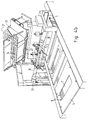
- An exemplary embodiment of such a combined punching unit 121 is shown in FIG. 8a.
- the combined punching unit 121 has a column frame with four vertical columns 122, on which an upper table 123 and a lower table 124 are guided.
- the distance between the first and second columns - in the direction of pallet movement, and the dimensions of the tables 123, 124 are selected sufficiently to accommodate two pallets 5.
- the upper table 123 is slightly vertically adjustable for adjustment purposes; for this purpose, a motor-driven chain synchronism is provided, as has been described above with reference to the upper forming table 80 of the press 70 of the forming station 50.
- the under table 124 is vertically adjustable along the columns 122. Starting from a release position to the upper table 123, the lower table 124 passes through a punching position adjacent to the upper table 123 in order to then assume the release position again.
- a drive 125 with a geared motor 126 is used to adjust the lower table 124 and drives a crank drive 128 in a non-positive manner via a worm gear 127 with a hollow shaft and shrink disk transmission. Its crank 129 is connected via a connecting rod 130 to a connecting rod bearing 131 which is guided in a vertically adjustable manner. Furthermore, a double toggle lever arrangement 132 is provided with a toggle lever shaft 133 on which a number of arms are mounted, as is described in detail for the double toggle lever arrangement 110 of the drive 100 of the press 70. Due to the double toggle lever arrangement 132, the punching unit 121 can also be operated on one side with only one tool 135 or 140. With a drive power of 3 kW for the geared motor 126, a punching force of 0.4 mega newtons can be achieved.
- the cutting or punching tool 136 for the punch punch 135 and the cutting or punching tool 141 for the diarrhea punch 140 are fastened to the lower table 124.
- Suitable abutments or counterparts 137 and 142 are attached to the upper table 123.
- All tool parts 136, 137 and 141, 142 are attached to holding plates 138, 138 'and 143, 143', respectively, which can be fixed in place on the lower table 124 or upper table 123.
- Each profiled terminal block 150, 150 ' comprises an edge section of a holding plate 138, 138'; 143, 143 'and presses them against a table top of the lower table 124 or the upper table 123.
- the clamping bar 150 can take a locking position (left illustration in FIG. 8b) or the clamping bar 150' can assume a tool change position (right illustration in FIG. 8b).
- bores 151 extend in the vertical direction through the terminal strips 150, 150 '.
- Each bolt 152 has a projecting head 153 at one end and an externally threaded section 154 at the other end.
- the bolts 152 are guided through the bores 151 and screwed with the threaded sections 154 into suitable internal threaded sections 156, which are recessed in the plate 124.
- a plate spring 155 is clamped between the bolt head 153 and the terminal block 150, 150 'and presses the terminal block 150, 150' against the holding plate 138.
- a number of punches 158 are provided in order to bring the clamping strip 150 'from the fixing position against the spring force of the plate spring 155 into the tool change position. These stamps 158 protrude through bores 157 which are recessed in the plate 124 and act on the underside of the clamping strip 150 '.
- Each punch 158 is connected to a piston of a hydraulically actuated piston / cylinder arrangement 159. Each punch 158 is only moved into the terminal block release position or tool change position and held there when the piston / cylinder arrangement 159 is pressurized with pressure medium.
- the lower table 124 has a recess in which a pneumatically operated ejector 145 is accommodated, one vertically adjustable stamp 146.
- This stamp 146 can pass through aligned bores in the table top of the lower table 124, through the cutting or punching tool 141 and through the adapted die 142 of the diarrhea punch 140 and can thereby punch a punched part 4 'punched out of the deformed film 4 into a stack magazine 147 slide in, which is inserted in the upper table 123.
- the stack magazine 147 is oriented essentially vertically and delimits a stack cage in which the stamped parts 4 'are collected. From time to time, the punched parts 4 'are removed from the stacking cage by an operator.
- the lead frame remains on the pallet 5, is conveyed with it to the removal station 160 and there arrives in a collecting container 163 (cf. FIG. 3).
- the centering of the pallets 5 on the cutting or punching tool 136 of the hole punch and / or on the cutting or punching tool 141 of the diarrhea punch 140 takes place within the punching station 120 in the same way as the centering of the pallets 5 on the forming tool 51 within the forming station 50.
- Figure 9 shows schematically the attachment of a pallet 5 to a transport chain 10.
- a plastic pallet holder 9 is rotatably attached to a link of the chain 10 and engages behind a further chain link, so that the pallet holder 9 also the path of movement on the circumference of a Deflection roller can follow.
- a frame-like, rectangular sheet metal plate is fastened to the pallet holder 9 with the aid of quick-release fastening means 14, for example bayonet locks.
- Two centering pins 8 protrude vertically from the top of the pallet 5.
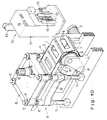
- FIG. 10 shows a perspective view of a molding station 50 and a section of the pallet strand 6 guided through the molding station, as well as the source 170 for compressed air arranged next to it.
- Each pallet 5 is on its opposite narrow sides on a pallet holder 9 supported, which is attached to a chain link of a driven rotating chain 10.
- the two chains are guided parallel at a distance over the deflection rollers 11 'and 11''.
- the electric motor 15 is used to drive the driven deflection roller 11 ′.
- the pallet strand 6 attached to the chains 10 is fed to the molding station 50 through the working space between the upper molding table 80 and the lower molding table 90.
- a chain guard frame 12 is arranged at a distance from the movable pallet strand 6.
- a schematically illustrated compressed air generator 170 which has a multi-stage compressor housed within the housing 171, a condensation dryer 172, a compressed air supply bottle 173, pressure reducing devices 174 and conventional control devices 175 and display devices 176.
- a line (not shown) leads to the control members 59 at the molding station 50 in order to introduce compressed air into the mold trough 57, which is formed in the molding tool 51, if necessary.
Landscapes
- Engineering & Computer Science (AREA)
- Mechanical Engineering (AREA)
- Blow-Moulding Or Thermoforming Of Plastics Or The Like (AREA)
- Casting Or Compression Moulding Of Plastics Or The Like (AREA)
Applications Claiming Priority (2)
| Application Number | Priority Date | Filing Date | Title |
|---|---|---|---|
| DE4113568 | 1991-04-25 | ||
| DE19914113568 DE4113568C1 (fr) | 1991-04-25 | 1991-04-25 |
Publications (1)
| Publication Number | Publication Date |
|---|---|
| EP0510702A1 true EP0510702A1 (fr) | 1992-10-28 |
Family
ID=6430363
Family Applications (1)
| Application Number | Title | Priority Date | Filing Date |
|---|---|---|---|
| EP92107103A Withdrawn EP0510702A1 (fr) | 1991-04-25 | 1992-04-24 | Appareils de formation de feuilles en matière plastique sous haute pression |
Country Status (4)
| Country | Link |
|---|---|
| EP (1) | EP0510702A1 (fr) |
| CA (1) | CA2066937C (fr) |
| DE (1) | DE4113568C1 (fr) |
| GB (1) | GB2255524B (fr) |
Cited By (4)
| Publication number | Priority date | Publication date | Assignee | Title |
|---|---|---|---|---|
| KR100431456B1 (ko) * | 2001-03-12 | 2004-05-14 | 이춘식 | 음식보관용기 적재장치 |
| KR100431455B1 (ko) * | 2001-03-12 | 2004-05-14 | 이춘식 | 음식보관용기 고정장치 |
| CN116174969A (zh) * | 2023-04-19 | 2023-05-30 | 华安钢宝利汽车板加工(重庆)有限公司 | 一种便于转运式激光焊接用落料堆垛装置 |
| CN118617717A (zh) * | 2024-08-14 | 2024-09-10 | 浙江云中包装有限公司 | 一种包装盒的吸塑成型模具及吸塑方法 |
Families Citing this family (24)
| Publication number | Priority date | Publication date | Assignee | Title |
|---|---|---|---|---|
| IT1264854B1 (it) * | 1993-06-18 | 1996-10-17 | Comi Srl | Impianto per la termoformatura di materiali in lastra, provvisto di stazioni di preriscaldamento |
| FR2744200B1 (fr) * | 1996-01-26 | 1998-03-13 | Brandsatch Holding Sa | Boite de chauffe comportant des tubes a infra-rouges pour le chauffage d'une feuille de matiere plastique avant son formage et procede de chauffage mis en oeuvre avec une telle boite de chauffe |
| DE19717740C2 (de) * | 1997-04-26 | 2001-07-05 | Schoenberg & Cerny Gmbh Wien | Kunststoff-Formkörper mit integriertem optoelektronischem Leuchtfeld und Verfahren zu seiner Herstellung |
| FR2766123B1 (fr) * | 1997-07-21 | 1999-10-08 | Erca | Installation et procede de fabrication de recipients par thermoformage |
| DE19755952C1 (de) * | 1997-12-16 | 1998-12-10 | Curt Niebling | Dünnwandiges, elektro-magnetisch abschirmendes, tiefgezogenes Formteil, Verfahren zu dessen Herstellung, und ein bei diesem Verfahren einsetzbares Zwischenprodukt |
| DE10058090C1 (de) * | 2000-11-24 | 2002-10-02 | Mcgavigan John Ltd | Verfahren zur Herstellung von, zumindest in Abschnitten durchleuchtbaren und dort bedruckten Kunststoff-Formteilen mit beflockter Sichtseite |
| DE102006059203A1 (de) * | 2006-12-13 | 2008-06-19 | Lyttron Technology Gmbh | Biegbares 3D-EL-HDFV Element und Herstellungsverfahren und Anwendung |
| DE102007009583B4 (de) | 2007-02-26 | 2013-10-02 | Foliotec Gmbh | Verfahren zur Herstellung eines Verbundformteils |
| DE102007046472B4 (de) | 2007-09-28 | 2013-12-24 | Bayer Materialscience Aktiengesellschaft | Verfahren zur Herstellung eines tiefgezogenen Folienteils aus Polycarbonat oder aus Polymethylmethacrylat |
| DE102008050564B4 (de) | 2008-09-22 | 2011-01-20 | Curt Niebling | Formwerkzeug und Verfahren zur Hochdruckumformung eines einlagigen oder mehrlagigen Schichtstoffes |
| DE102009048334A1 (de) | 2009-10-06 | 2011-04-21 | Curt Niebling | 3D-Folienteil und Verfahren zu seiner Herstellung |
| EP2335905A1 (fr) | 2009-12-17 | 2011-06-22 | Bayer MaterialScience AG | Procédé de fabrication d'une partie de feuille emboutie en matière synthétique thermoplastique |
| DE102010021892B4 (de) | 2010-05-28 | 2014-03-20 | Curt Niebling jun. | Verfahren und Vorrichtung zur Kaschierung eines 3D-Trägerteils mit einem Schichtstoff |
| NZ603877A (en) * | 2010-06-03 | 2014-08-29 | Cryovac Inc | Plate and apparatus for forming a plastic material flanged hollow article |
| PT2397307E (pt) | 2010-06-18 | 2013-05-29 | Geiss Ag | Sistema e processo para a conformação térmica de placas |
| DE102011050585B4 (de) * | 2011-05-24 | 2014-05-08 | Kunststoff Helmbrechts Ag | Verfahren zur Herstellung eines Kunststoffformkörpers als Anzeige- und/oder Funktionselement und Kunststoffformkörper |
| US11135760B2 (en) | 2013-08-20 | 2021-10-05 | Sabic Global Technologies B.V. | Process for forming articles from extruded polymer sheet |
| DE102013021300C5 (de) * | 2013-12-19 | 2018-11-22 | Jörg von Seggern Maschinenbau GmbH | Hubvorrichtung für ein Werkzeug |
| DE102016004047B4 (de) | 2016-04-04 | 2017-10-19 | Niebling Gmbh | Verfahren und Formwerkzeug zur Warmumformung eines ebenen thermoplastischen Schichtstoffes |
| IT201700014643A1 (it) * | 2017-02-10 | 2018-08-10 | I M A Industria Macch Automatiche S P A In Sigla Ima S P A | Gruppo di fabbricazione di contenitori riempibili e linea di confezionamento comprendente tale gruppo di fabbricazione. |
| DE102022105839A1 (de) * | 2022-03-14 | 2023-09-14 | Covestro Deutschland Ag | Verfahren zum Herstellen eines Kunststoff-Formteils |
| DE102022105840A1 (de) | 2022-03-14 | 2023-09-14 | tooz technologies GmbH | Verfahren zum Herstellen eines Kunststoff-Formteils |
| DE102022128541A1 (de) | 2022-10-27 | 2024-05-02 | Bundesdruckerei Gmbh | Stanzanordnung und Verfahren zum Betreiben einer Stanzanordnung |
| DE202023104500U1 (de) | 2023-08-09 | 2023-09-13 | Marquardt Gmbh | System aus Umformwerkzeug und Hilfsfolie zur Herstellung eines Dekorteils mit dreidimensional geformter Oberfläche |
Citations (5)
| Publication number | Priority date | Publication date | Assignee | Title |
|---|---|---|---|---|
| GB791097A (en) * | 1954-05-03 | 1958-02-26 | Ryburn Engineering Company Ltd | An improved method of and apparatus for producing thin-walled vessels from thermoplastic material |
| EP0322697A1 (fr) * | 1987-12-28 | 1989-07-05 | TECNOFORM S.r.l. | Machine pour la fabrication d'articles thermoformés |
| EP0363918A2 (fr) * | 1988-10-13 | 1990-04-18 | QuesTech Ventures, Inc. | Récipient résistant au passage dans une cornue |
| WO1991001214A1 (fr) * | 1989-07-22 | 1991-02-07 | Verson Hme Limited | Estampeuse et procede d'usinage d'un materiau |
| EP0371425B1 (fr) * | 1988-12-01 | 1995-03-08 | Curt Niebling | Procédé de fabrication de pièces embouties en matière plastique |
Family Cites Families (1)
| Publication number | Priority date | Publication date | Assignee | Title |
|---|---|---|---|---|
| IT1215197B (it) * | 1986-10-31 | 1990-01-31 | Monetti Spa | Automatizzata di prodotti di lamina procedimento per la fabbricazione to plastico |
-
1991
- 1991-04-25 DE DE19914113568 patent/DE4113568C1/de not_active Expired - Lifetime
-
1992
- 1992-04-23 GB GB9208845A patent/GB2255524B/en not_active Expired - Lifetime
- 1992-04-23 CA CA 2066937 patent/CA2066937C/fr not_active Expired - Fee Related
- 1992-04-24 EP EP92107103A patent/EP0510702A1/fr not_active Withdrawn
Patent Citations (5)
| Publication number | Priority date | Publication date | Assignee | Title |
|---|---|---|---|---|
| GB791097A (en) * | 1954-05-03 | 1958-02-26 | Ryburn Engineering Company Ltd | An improved method of and apparatus for producing thin-walled vessels from thermoplastic material |
| EP0322697A1 (fr) * | 1987-12-28 | 1989-07-05 | TECNOFORM S.r.l. | Machine pour la fabrication d'articles thermoformés |
| EP0363918A2 (fr) * | 1988-10-13 | 1990-04-18 | QuesTech Ventures, Inc. | Récipient résistant au passage dans une cornue |
| EP0371425B1 (fr) * | 1988-12-01 | 1995-03-08 | Curt Niebling | Procédé de fabrication de pièces embouties en matière plastique |
| WO1991001214A1 (fr) * | 1989-07-22 | 1991-02-07 | Verson Hme Limited | Estampeuse et procede d'usinage d'un materiau |
Cited By (5)
| Publication number | Priority date | Publication date | Assignee | Title |
|---|---|---|---|---|
| KR100431456B1 (ko) * | 2001-03-12 | 2004-05-14 | 이춘식 | 음식보관용기 적재장치 |
| KR100431455B1 (ko) * | 2001-03-12 | 2004-05-14 | 이춘식 | 음식보관용기 고정장치 |
| CN116174969A (zh) * | 2023-04-19 | 2023-05-30 | 华安钢宝利汽车板加工(重庆)有限公司 | 一种便于转运式激光焊接用落料堆垛装置 |
| CN116174969B (zh) * | 2023-04-19 | 2023-11-07 | 华安钢宝利汽车板加工(重庆)有限公司 | 一种便于转运式激光焊接用落料堆垛装置 |
| CN118617717A (zh) * | 2024-08-14 | 2024-09-10 | 浙江云中包装有限公司 | 一种包装盒的吸塑成型模具及吸塑方法 |
Also Published As
| Publication number | Publication date |
|---|---|
| DE4113568C1 (fr) | 1992-05-21 |
| CA2066937A1 (fr) | 1992-10-26 |
| GB2255524B (en) | 1995-05-03 |
| CA2066937C (fr) | 1999-02-16 |
| GB2255524A (en) | 1992-11-11 |
| GB9208845D0 (en) | 1992-06-10 |
Similar Documents
| Publication | Publication Date | Title |
|---|---|---|
| DE4113568C1 (fr) | ||
| DE10030010C2 (de) | Verfahren zum Herstellen eines Behälters aus einer thermoplastischen Kunststofffolie und Formwerkzeug zur Durchführung des Verfahrens | |
| EP1882564B1 (fr) | Presse de découpage et de rainurage ayant une pression de coupe et de rainurage réglable | |
| DE69309312T2 (de) | Verfahren und vorrichtung zum wechseln von formen in warmformpressen | |
| DE1454962B1 (de) | Vorrichtung zur Vakuumverformung eines thermoplastischen Kunststoffbandes | |
| EP2351634B1 (fr) | Outil pour une presse de découpage et de cannelage | |
| DE2839269A1 (de) | Gesenkpresse | |
| DE102004027949B4 (de) | Vorrichtung zum Herstellen eines Bandes von etikettierten Behältern aus einer erwärmten thermoplastischen Kunststofffolie | |
| EP0538570A1 (fr) | Dispositif pour fabriquer un emballage | |
| DE4425139A1 (de) | Etiketteneinlegeverfahren und -vorrichtung | |
| DE3432700C2 (fr) | ||
| EP0366986B1 (fr) | Dispositif pour nettoyer un moule de machines à travailler les matières plastiques | |
| WO1989005719A1 (fr) | Procede et installation pour fabriquer des pieces moulees en matiere plastique | |
| DE4301200A1 (de) | Bandstahlschnittwerkzeug zum Austrennen von tiefgezogenen Formteilen | |
| EP3450134B1 (fr) | Station de formage pour une emboutisseuse-enveloppeuse sous pellicule et procédé de changement d'un poinçon de formage | |
| DE69718274T2 (de) | Spritzgiessmaschine und Spritzgiessverfahren zur Dekoration von Schichten | |
| DE102007011292B4 (de) | Formwerkzeug zum Aufbringen eines Etiketts auf ein tiefgezogenes Formteil und Verfahren zum Betreiben des Formwerkzeugs | |
| DE29713665U1 (de) | Vorrichtung zum thermischen Formen von Kunststoffolien | |
| DE2311706A1 (de) | Vorrichtung zur herstellung von verschiedenen betonplatten | |
| EP1311373B1 (fr) | Appareil de decoupage, particulierement adapte pour former des etiquettes et des elements en feuille du meme type | |
| DE2020401A1 (de) | Vorrichtung zum Warmverformen von Kunststoff-Folien od.dgl. | |
| DE69903712T2 (de) | Warmformverfahren und vorrichtung | |
| DE69615150T2 (de) | Verfahren und vorrichtung zum laden von etiketten in eine form einer warmformmaschine | |
| DE4406057C2 (de) | Anlage zur Herstellung und Fertigbearbeitung von Kunststoff-Formteilen | |
| EP1025978B1 (fr) | Dispositif de thermoformage de récipients à partir d'un film thermoplastique |
Legal Events
| Date | Code | Title | Description |
|---|---|---|---|
| PUAI | Public reference made under article 153(3) epc to a published international application that has entered the european phase |
Free format text: ORIGINAL CODE: 0009012 |
|
| AK | Designated contracting states |
Kind code of ref document: A1 Designated state(s): AT CH DE ES FR IT LI SE |
|
| STAA | Information on the status of an ep patent application or granted ep patent |
Free format text: STATUS: THE APPLICATION IS DEEMED TO BE WITHDRAWN |
|
| 18D | Application deemed to be withdrawn |
Effective date: 19930429 |