EP0509847A2 - Vorrichtung zur Messung der Brechungsindexquerschnittverteilung eines optischen Wellenleiters - Google Patents
Vorrichtung zur Messung der Brechungsindexquerschnittverteilung eines optischen Wellenleiters Download PDFInfo
- Publication number
- EP0509847A2 EP0509847A2 EP92303543A EP92303543A EP0509847A2 EP 0509847 A2 EP0509847 A2 EP 0509847A2 EP 92303543 A EP92303543 A EP 92303543A EP 92303543 A EP92303543 A EP 92303543A EP 0509847 A2 EP0509847 A2 EP 0509847A2
- Authority
- EP
- European Patent Office
- Prior art keywords
- optical waveguide
- light
- light receiving
- receiving unit
- refractive index
- Prior art date
- Legal status (The legal status is an assumption and is not a legal conclusion. Google has not performed a legal analysis and makes no representation as to the accuracy of the status listed.)
- Withdrawn
Links
- 230000003287 optical effect Effects 0.000 title claims abstract description 69
- 239000000758 substrate Substances 0.000 claims abstract description 5
- 238000000034 method Methods 0.000 description 9
- 239000007788 liquid Substances 0.000 description 2
- 230000007423 decrease Effects 0.000 description 1
- 230000001066 destructive effect Effects 0.000 description 1
- 238000010586 diagram Methods 0.000 description 1
- 230000004907 flux Effects 0.000 description 1
- 238000005259 measurement Methods 0.000 description 1
Images


Classifications
-
- G—PHYSICS
- G01—MEASURING; TESTING
- G01N—INVESTIGATING OR ANALYSING MATERIALS BY DETERMINING THEIR CHEMICAL OR PHYSICAL PROPERTIES
- G01N21/00—Investigating or analysing materials by the use of optical means, i.e. using sub-millimetre waves, infrared, visible or ultraviolet light
- G01N21/17—Systems in which incident light is modified in accordance with the properties of the material investigated
- G01N21/41—Refractivity; Phase-affecting properties, e.g. optical path length
- G01N21/412—Index profiling of optical fibres
Definitions
- the present invention relates to apparatus for measuring the cross-sectional distribution of the refractive index of an optical waveguide for use in e.g. optical communications.
- RNF method refracted near field method
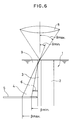
- An optical waveguide substrate 1 comprising an optical waveguide portion 3 on one side of a substrate portion 2 is immersed in a liquid 9 having refractive index of n L , which is close to the refractive index n(r) of the optical waveguide portion 3.
- a laser beam is focussed by an objective lens 8 onto the end surface of the optical waveguide portion 3 at a maximum angle of incidence ⁇ , and the light leaking out of the optical waveguide portion 3 is detected and the refractive index of the optical waveguide portion 3 is measured.
- the exit angle ⁇ changes according to the refractive index n(r) at each point. Specifically, the exit angle ⁇ decreases at those points having a higher refractive index and increases at those points having a lower refractive index.
- the refractive index n(r) of the optical waveguide portion 3 can be obtained.
- Apparatus for measuring the cross-sectional distribution of the refractive index of an optical waveguide utilising the RNF method is based on the above principle.
- a detector 5 for receiving the light 4 leaking out of the optical waveguide portion 3 is provided beside, i.e. laterally adjacent, the optical waveguide portion 3.
- a shield plate 6 comprising a semi-circular disk is provided for shielding that portion of the leaking light 4 closest to the optical waveguide portion 3.
- the detector 5 receives the leaking light 4 in a semi-annular shape, i.e. that portion of the light which is closest to the optical waveguide portion 3 is not received.
- the amount of light received is given by the following equation (2), in which the maximum angle of the incident light to the optical axis at the light receiving point, i.e. the focal point of the lens 8, is ⁇ max and the angle corresponding to that at which the incident light just passes the shield plate 6 is ⁇ min .
- I( ⁇ ) represents the intensity distribution of the incident light based on the angle of incidence.
- the maximum exit angle ⁇ max of the leaking light changes in accordance with the refracting power of the optical waveguide portion 3, that is to say, as the point of incidence of the light on the detector 5 on the outermost side is moved, and is primarily determined by the point where the light enters the optical waveguide portion 3 and also by the position of the edge of the shield plate 6 and is not influenced by the refractive index of the optical waveguide portion 3.
- the angle of incidence ⁇ min is an important factor for determining the refractive index of the optical waveguide portion 3. Specifically, the value for the amount of light obtained by the above equation (2) changes in accordance with the refractive index.
- Equation (6) a correction factor ⁇ n (r) can be obtained when the laser spot position is scanned in the direction of the thickness of the optical waveguide portion, or the direction perpendicular thereto and the change of light quantity ⁇ P is measured.
- ⁇ P a ⁇ n(r)
- the proportional constant a is determined by the refractive index n L which is already known.
- the relationship between ⁇ n and ⁇ P is shown in the diagrams of Figures 4 and 5. These Figures show the change in the light quantity and the change in the refractive index which are obtained when the laser spot position is scanned in the direction of the thickness of the optical waveguide portion.
- the incident light intensity distribution I ( ⁇ ) is a Gaussian distribution rather than a Lambert distribution, and the change in the light quantity and the change in the refractive index are not so simple as in equation (6).
- the correction factor ⁇ n(r) can, however, be obtained by calculation.
- a shield plate is provided to shield that part of the leaking light which is closest to the optical axis.
- the waveguide to be measured is extremely small and the range of the leaking light is extremely limited. Therefore, when a shield plate is to be provided, there are considerable restrictions on the method of supporting it, its shape, etc., and this results in troublesome and difficult procedure.
- apparatus for measuring the cross-sectional distribution of the refractive index of an optical waveguide including an optical waveguide portion and a substrate portion comprises means for holding the optical waveguide in a predetermined position, a projection system for radiating a focussed beam of light to one end surface of the optical waveguide portion and a light receiving unit arranged so that, in use, light leaking from the optical waveguide is incident on it, whereby the change in the amount of light incident on the light receiving unit at the point of incidence of the focussed beam of light is moved over the end surface of the optical waveguide portion is indicative of the cross-sectional distribution of the refractive index of the optical waveguide, and is characterised in that the light receiving unit is so constructed or so positioned relative to the optical waveguide that that portion of leaking light closest to the optical waveguide is not incident on the light receiving unit but passes between the light receiving unit and the optical waveguide or is absorbed by some portion of the light receiving unit other than its light receiving surface or by some other component.
- the light receiving unit or at least the light receiving surface of the detector 5 is sufficiently extensive that even the outermost edge of the leaking luminous flux or light 4 is incident on it.
- the inner edge 7 of the light receiving surface i.e. the edge which is closest to the optical axis is positioned within the leaking light 4, so that the portion of the leaking light closer to the optical axis is not received.
- the exit angle ⁇ of the leaking light incident on the edge 7 of the light receiving surface of the detector 5 has the value ⁇ min in equation 4.
- a computing element calculates the distribution of the refractive index in accordance with equations (5) and (6) based on signals from the detector 5.
- the detector 5 such as that shown in Figure 2, in which it has an extensive planar light receiving surface in which a part-circular cut-out portion is provided at the position closest to the optical axis, or that shown in Figure 3, in which it has an elongate rectangular shape and its inner edge 7 is spaced by an appropriate distance away from the optical waveguide portion 3.
- the apparatus of the present invention is considerably simpler than the known apparatus because there is no need to provide a shield plate in the optical path.
Landscapes
- Physics & Mathematics (AREA)
- Health & Medical Sciences (AREA)
- Life Sciences & Earth Sciences (AREA)
- Chemical & Material Sciences (AREA)
- Analytical Chemistry (AREA)
- Biochemistry (AREA)
- General Health & Medical Sciences (AREA)
- General Physics & Mathematics (AREA)
- Immunology (AREA)
- Pathology (AREA)
- Investigating Or Analysing Materials By Optical Means (AREA)
Applications Claiming Priority (2)
| Application Number | Priority Date | Filing Date | Title |
|---|---|---|---|
| JP115480/91 | 1991-04-19 | ||
| JP11548091A JPH05332880A (ja) | 1991-04-19 | 1991-04-19 | 光導波路断面屈折率分布測定装置 |
Publications (2)
| Publication Number | Publication Date |
|---|---|
| EP0509847A2 true EP0509847A2 (de) | 1992-10-21 |
| EP0509847A3 EP0509847A3 (en) | 1993-07-21 |
Family
ID=14663569
Family Applications (1)
| Application Number | Title | Priority Date | Filing Date |
|---|---|---|---|
| EP19920303543 Withdrawn EP0509847A3 (en) | 1991-04-19 | 1992-04-21 | Measuring the cross-sectional distribution of the refractive index of optical waveguides |
Country Status (2)
| Country | Link |
|---|---|
| EP (1) | EP0509847A3 (de) |
| JP (1) | JPH05332880A (de) |
Families Citing this family (3)
| Publication number | Priority date | Publication date | Assignee | Title |
|---|---|---|---|---|
| WO2013128691A1 (ja) | 2012-02-27 | 2013-09-06 | 住友ベークライト株式会社 | 光導波路、光配線部品、光導波路モジュールおよび電子機器 |
| US9720171B2 (en) | 2012-06-19 | 2017-08-01 | Sumitomo Bakelite Co., Ltd. | Optical waveguide, optical interconnection component, optical module, opto-electric hybrid board, and electronic device |
| CN110022632A (zh) * | 2019-04-19 | 2019-07-16 | 青岛亿联客信息技术有限公司 | 一种灯具光通量的调节方法、装置、系统及可读存储介质 |
Family Cites Families (1)
| Publication number | Priority date | Publication date | Assignee | Title |
|---|---|---|---|---|
| US4468118A (en) * | 1982-09-17 | 1984-08-28 | At&T Technologies, Inc. | Method and apparatus for determining index of refraction profiles of optical fibers |
-
1991
- 1991-04-19 JP JP11548091A patent/JPH05332880A/ja active Pending
-
1992
- 1992-04-21 EP EP19920303543 patent/EP0509847A3/en not_active Withdrawn
Also Published As
| Publication number | Publication date |
|---|---|
| JPH05332880A (ja) | 1993-12-17 |
| EP0509847A3 (en) | 1993-07-21 |
Similar Documents
| Publication | Publication Date | Title |
|---|---|---|
| US4647193A (en) | Optical target ranging apparatus | |
| US5080484A (en) | Method of measuring the contact angle of wetting liquid on a solid surface | |
| US4816670A (en) | Optical measuring head | |
| AU2005100959A4 (en) | Laser Distance Measuring Device | |
| KR910021571A (ko) | 코팅 두께 측정 방법 및 장치 | |
| US7298468B2 (en) | Method and measuring device for contactless measurement of angles or angle changes on objects | |
| US4893929A (en) | Particle analyzing apparatus | |
| EP0509849A2 (de) | Verfahren zur Messung der Brechungsindexquerschnittverteilung eines optischen Wellenleiters | |
| EP0447991B1 (de) | Gerät zur Messung der Grössenverteilung von beugenden/streuenden Teilchen | |
| EP0509848A2 (de) | Verfahren und Vorrichtung zur Messung der Brechungsindexquerschnittverteilung eines optischen Wellenleiters | |
| KR100647749B1 (ko) | 광산란 측정장치 | |
| JPH05332880A (ja) | 光導波路断面屈折率分布測定装置 | |
| EP0578482A1 (de) | Vorrichtung zur Messung der Brechungsindexquerschnittverteilung eines optischen Wellenleiters | |
| JPS58139043A (ja) | レンズの集光性能測定装置 | |
| JP2666032B2 (ja) | 散乱光と散乱角度分布の測定方法 | |
| JPS57199909A (en) | Distance measuring device | |
| US5497228A (en) | Laser bevel meter | |
| JP2565274B2 (ja) | 高さ測定装置 | |
| JP3329950B2 (ja) | 光変位測定装置 | |
| JPH1048130A (ja) | 屈折率測定方法及びその装置 | |
| RU1770850C (ru) | Способ определени спектральных направленно-полусферических коэффициентов отражени образцов | |
| SU798552A1 (ru) | Способ определени размеров сферичес-КиХ МиКРОчАСТиц | |
| JPS5451863A (en) | Surface roughness measuring apparatus | |
| JPH0678889B2 (ja) | 高さ測定装置 | |
| RU98110769A (ru) | Способ и устройство для определения показателя преломления окружающей среды |
Legal Events
| Date | Code | Title | Description |
|---|---|---|---|
| PUAI | Public reference made under article 153(3) epc to a published international application that has entered the european phase |
Free format text: ORIGINAL CODE: 0009012 |
|
| AK | Designated contracting states |
Kind code of ref document: A2 Designated state(s): CH DE FR GB LI |
|
| PUAL | Search report despatched |
Free format text: ORIGINAL CODE: 0009013 |
|
| AK | Designated contracting states |
Kind code of ref document: A3 Designated state(s): CH DE FR GB LI |
|
| 17P | Request for examination filed |
Effective date: 19940120 |
|
| 17Q | First examination report despatched |
Effective date: 19951128 |
|
| STAA | Information on the status of an ep patent application or granted ep patent |
Free format text: STATUS: THE APPLICATION IS DEEMED TO BE WITHDRAWN |
|
| 18D | Application deemed to be withdrawn |
Effective date: 19960410 |