EP0509848A2 - Verfahren und Vorrichtung zur Messung der Brechungsindexquerschnittverteilung eines optischen Wellenleiters - Google Patents
Verfahren und Vorrichtung zur Messung der Brechungsindexquerschnittverteilung eines optischen Wellenleiters Download PDFInfo
- Publication number
- EP0509848A2 EP0509848A2 EP92303544A EP92303544A EP0509848A2 EP 0509848 A2 EP0509848 A2 EP 0509848A2 EP 92303544 A EP92303544 A EP 92303544A EP 92303544 A EP92303544 A EP 92303544A EP 0509848 A2 EP0509848 A2 EP 0509848A2
- Authority
- EP
- European Patent Office
- Prior art keywords
- optical waveguide
- light
- refractive index
- receiving unit
- light receiving
- Prior art date
- Legal status (The legal status is an assumption and is not a legal conclusion. Google has not performed a legal analysis and makes no representation as to the accuracy of the status listed.)
- Ceased
Links
Images

Classifications
-
- G—PHYSICS
- G01—MEASURING; TESTING
- G01N—INVESTIGATING OR ANALYSING MATERIALS BY DETERMINING THEIR CHEMICAL OR PHYSICAL PROPERTIES
- G01N21/00—Investigating or analysing materials by the use of optical means, i.e. using sub-millimetre waves, infrared, visible or ultraviolet light
- G01N21/17—Systems in which incident light is modified in accordance with the properties of the material investigated
- G01N21/41—Refractivity; Phase-affecting properties, e.g. optical path length
- G01N21/412—Index profiling of optical fibres
Definitions
- the present invention relates to an apparatus and a method of measuring the cross-sectional distribution of the refractive index of an optical waveguide for use in e.g. optical communications.
- RNF method refracted near field method
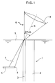
- An optical waveguide substrate 1 comprising an optical waveguide portion 3 on one side of a substrate portion 2 is immersed in a liquid 9 having refractive index of n L , which is close to the refractive index n(r) of the optical waveguide portion 3.
- a laser beam is focussed by an objective lens 8 onto the end surface of the optical waveguide portion 3 at a maximum angle of incidence ⁇ , and the light leaking out of the optical waveguide portion 3 is detected and the refractive index of the optical waveguide portion 3 is measured.
- the exit angle ⁇ changes according to the refractive index n(r) at each point. Specifically, the exit angle ⁇ decreases at those points having a higher refractive index and increases at those points having a lower refractive index.
- the refractive index n(r) of the optical waveguide portion 3 can be obtained.
- Apparatus for measuring the cross-sectional distribution of the refractive index of an optical waveguide utilising the RNF method is based on the above principle.
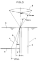
- a detector 5 for receiving the light 4 leaking out of the optical waveguide portion 3 is provided beside, i.e. laterally adjacent, the optical waveguide portion 3.
- a shield plate 6 comprising a semi-circular disk is provided for shielding that portion of the leaking light 4 closest to the optical waveguide portion 3.
- the detector 5 receives the leaking light 4 in a semi-annular shape, i.e. that portion of the light which is closest to the optical waveguide portion 3 is not received.
- the amount of light received is given by the following equation (2), in which the maximum angle of the incident light to the optical axis at the light receiving point, i.e. the focal point of the lens 8, is ⁇ max and the angle corresponding to that at which the incident light just passes the shield plate 6 is ⁇ min .
- I( ⁇ ) represents the intensity distribution of the incident light based on the angle of incidence.
- the maximum exit angle ⁇ max of the leaking light changes in accordance with the refracting power of the optical waveguide portion 3, that is to say, as the point of incidence of the light on the detector 5 on the outermost side is moved, and is primarily determined by the point where the light enters the optical waveguide portion 3 and also by the position of the edge of the shield plate 6 and is not influenced by the refractive index of the optical waveguide portion 3.
- the angle of incidence ⁇ min is an important factor for determining the refractive index of the optical waveguide portion 3. Specifically, the value for the amount of light obtained by the above equation (2) changes in accordance with the refractive index.
- Equation (6) a correction factor ⁇ n (r) can be obtained when the laser spot position is scanned in the direction of the thickness of the optical waveguide portion, or the direction perpendicular thereto and the change of light quantity ⁇ P is measured.
- ⁇ P a ⁇ ⁇ n(r)
- the proportional constant a is determined by the refractive index n L , which is already known.
- the incident light intensity distribution I( ⁇ ) is a Gaussian distribution rather than a Lambert distribution, and the change in the light quantity and the change of refractive index are not as simple as in equation (6).
- the correction factor ⁇ n (r) can, however, be obtained by calculation.
- apparatus for measuring the cross-sectional distribution of the refractive index of an elongate optical waveguide including an optical waveguide portion and a substrate portion comprises means for holding the optical waveguide in a predetermined position, a projection system with an optical axis for radiating a focussed beam of light onto one end surface of the optical waveguide portion and a light receiving unit arranged laterally adjacent the optical waveguide for receiving light leaking from the optical waveguide, whereby change in the amount of light incident on the light receiving unit as the point of incidence of the focussed beam of light is moved over the end surface of the optical waveguide portion is indicative of the cross-sectional distribution of the refractive index of the optical waveguide, is characterised in that the optical axis of the projection system is inclined to the length of the optical waveguide and is directed generally towards the light receiving unit.
- the light receiving unit may be provided laterally adjacent either the optical waveguide portion or the substrate portion.
- the present invention also embraces an associated method of measuring the cross-sectional distribution of the refractive index of an elongate optical waveguide.
- a detector 5 for receiving the light 4 leaking out of the optical waveguide portion 3 is provided laterally adjacent the optical waveguide portion 3.
- the optical axis 13 of the projection system 12 is inclined to the direction of the length of the optical waveguide 1 such that it is directed generally towards the detector 5 and not parallel to the length of the waveguide, as is conventional.
- the maximum incident angle ⁇ max is the sum of the conventional angle ⁇ max and the angle of inclination of the optical axis 13 to the length of the waveguide 1.
- the light receiving unit i.e. at least the light receiving surface of detector 5, is sufficiently extensive relative to the leaking light 4 that substantially all the light 4 is incident on it. That end 7 of the detector 5 which is closest to the waveguide is positioned within the leaking light so that a portion of the leaking light 4 closer to the optical waveguide is not received.
- the exit angle ⁇ of the leaking light passing through the end edge 7 of the light receiving surface of the detector 5 is the same as ⁇ min of equation (4).
- a computing element calculates the distribution of the refractive index in accordance with equations (5) and (6) based on signals from the detector 5.
- the detector 5 may have a wide planar shape or it is may be of rectangular shape which is long enough to transverse the leaking light.
- the detector 5 is provided on the opposite side of the optical waveguide 1, i.e. laterally adjacent the substrate portion 2.
- the detector 5 is again sufficiently extensive relative to the leaking light 4 that substantially all the leaking light is received.
- the end edge 7 of the light receiving surface closest to the optical waveguide is positioned within the leaking light so that the portion of the leaking light closest to the optical waveguide is not received.
- the optical axis of the projections system is again inclined to the length of the waveguide but in the opposite sense to that shown in Figure 1 so it is again directed generally towards the detector 5.
- the angle of inclination of the optical axis of the projection system 12 can be selected at will to suit requirements.
Landscapes
- Physics & Mathematics (AREA)
- Health & Medical Sciences (AREA)
- Life Sciences & Earth Sciences (AREA)
- Chemical & Material Sciences (AREA)
- Analytical Chemistry (AREA)
- Biochemistry (AREA)
- General Health & Medical Sciences (AREA)
- General Physics & Mathematics (AREA)
- Immunology (AREA)
- Pathology (AREA)
- Investigating Or Analysing Materials By Optical Means (AREA)
Applications Claiming Priority (2)
| Application Number | Priority Date | Filing Date | Title |
|---|---|---|---|
| JP3115482A JPH05322702A (ja) | 1991-04-19 | 1991-04-19 | 光導波路断面屈折率分布測定装置 |
| JP115482/91 | 1991-04-19 |
Publications (2)
| Publication Number | Publication Date |
|---|---|
| EP0509848A2 true EP0509848A2 (de) | 1992-10-21 |
| EP0509848A3 EP0509848A3 (en) | 1993-07-28 |
Family
ID=14663614
Family Applications (1)
| Application Number | Title | Priority Date | Filing Date |
|---|---|---|---|
| EP19920303544 Ceased EP0509848A3 (en) | 1991-04-19 | 1992-04-21 | Measuring the cross-sectional distribution of the refractive index of an optical waveguide |
Country Status (3)
| Country | Link |
|---|---|
| US (1) | US5278628A (de) |
| EP (1) | EP0509848A3 (de) |
| JP (1) | JPH05322702A (de) |
Families Citing this family (1)
| Publication number | Priority date | Publication date | Assignee | Title |
|---|---|---|---|---|
| JP3210429B2 (ja) * | 1992-07-08 | 2001-09-17 | 株式会社トプコン | 光導波路断面屈折率分布測定装置 |
Family Cites Families (2)
| Publication number | Priority date | Publication date | Assignee | Title |
|---|---|---|---|---|
| GB2116708B (en) * | 1982-03-18 | 1985-09-18 | Nat Res Dev | Method of and apparatus for determining the radial refractive index profile of an optical specimen |
| US4468118A (en) * | 1982-09-17 | 1984-08-28 | At&T Technologies, Inc. | Method and apparatus for determining index of refraction profiles of optical fibers |
-
1991
- 1991-04-19 JP JP3115482A patent/JPH05322702A/ja active Pending
-
1992
- 1992-04-07 US US07/864,555 patent/US5278628A/en not_active Expired - Lifetime
- 1992-04-21 EP EP19920303544 patent/EP0509848A3/en not_active Ceased
Also Published As
| Publication number | Publication date |
|---|---|
| EP0509848A3 (en) | 1993-07-28 |
| JPH05322702A (ja) | 1993-12-07 |
| US5278628A (en) | 1994-01-11 |
Similar Documents
| Publication | Publication Date | Title |
|---|---|---|
| US4816670A (en) | Optical measuring head | |
| US4647193A (en) | Optical target ranging apparatus | |
| US6323954B1 (en) | Process and device for the detection or determination of the position of edges | |
| EP0279347B1 (de) | Optische Achsenverschiebungsfühler | |
| US7298468B2 (en) | Method and measuring device for contactless measurement of angles or angle changes on objects | |
| EP0492723B1 (de) | Vorrichtung zum optischen Messen der Höhe einer Oberfläche | |
| US4792695A (en) | Contact-free measuring apparatus having an F-theta-corrected, catadioptric objective and method for using the same | |
| EP0509849A2 (de) | Verfahren zur Messung der Brechungsindexquerschnittverteilung eines optischen Wellenleiters | |
| US4771181A (en) | Method for detecting dripping droplet with refracted and reflected light | |
| EP0509848A2 (de) | Verfahren und Vorrichtung zur Messung der Brechungsindexquerschnittverteilung eines optischen Wellenleiters | |
| EP0509847A2 (de) | Vorrichtung zur Messung der Brechungsindexquerschnittverteilung eines optischen Wellenleiters | |
| EP0447991B1 (de) | Gerät zur Messung der Grössenverteilung von beugenden/streuenden Teilchen | |
| JPS6432105A (en) | Angle deviation measuring instrument for flat plate member | |
| EP0578482B1 (de) | Vorrichtung zur Messung der Brechungsindexquerschnittverteilung eines optischen Wellenleiters | |
| JP3040131B2 (ja) | 球体表面の傷検査装置 | |
| JP2666032B2 (ja) | 散乱光と散乱角度分布の測定方法 | |
| JPS57199909A (en) | Distance measuring device | |
| US5497228A (en) | Laser bevel meter | |
| JP3329950B2 (ja) | 光変位測定装置 | |
| JP2565274B2 (ja) | 高さ測定装置 | |
| JP2722247B2 (ja) | 測定装置 | |
| SU798552A1 (ru) | Способ определени размеров сферичес-КиХ МиКРОчАСТиц | |
| JPS60211304A (ja) | 平行度測定装置 | |
| JPH10176927A (ja) | 傾斜センサ | |
| RU1770850C (ru) | Способ определени спектральных направленно-полусферических коэффициентов отражени образцов |
Legal Events
| Date | Code | Title | Description |
|---|---|---|---|
| PUAI | Public reference made under article 153(3) epc to a published international application that has entered the european phase |
Free format text: ORIGINAL CODE: 0009012 |
|
| AK | Designated contracting states |
Kind code of ref document: A2 Designated state(s): CH DE FR GB LI |
|
| PUAL | Search report despatched |
Free format text: ORIGINAL CODE: 0009013 |
|
| AK | Designated contracting states |
Kind code of ref document: A3 Designated state(s): CH DE FR GB LI |
|
| 17P | Request for examination filed |
Effective date: 19940127 |
|
| GRAG | Despatch of communication of intention to grant |
Free format text: ORIGINAL CODE: EPIDOS AGRA |
|
| 17Q | First examination report despatched |
Effective date: 19960214 |
|
| STAA | Information on the status of an ep patent application or granted ep patent |
Free format text: STATUS: THE APPLICATION HAS BEEN REFUSED |
|
| 18R | Application refused |
Effective date: 19960803 |