EP0509796A2 - Schaltung zur Aufhebung der Verschwommenheit - Google Patents
Schaltung zur Aufhebung der Verschwommenheit Download PDFInfo
- Publication number
- EP0509796A2 EP0509796A2 EP92303402A EP92303402A EP0509796A2 EP 0509796 A2 EP0509796 A2 EP 0509796A2 EP 92303402 A EP92303402 A EP 92303402A EP 92303402 A EP92303402 A EP 92303402A EP 0509796 A2 EP0509796 A2 EP 0509796A2
- Authority
- EP
- European Patent Office
- Prior art keywords
- circuit
- summing circuit
- weighted
- lines
- defuzzifier
- Prior art date
- Legal status (The legal status is an assumption and is not a legal conclusion. Google has not performed a legal analysis and makes no representation as to the accuracy of the status listed.)
- Withdrawn
Links
Images


Classifications
-
- G—PHYSICS
- G06—COMPUTING OR CALCULATING; COUNTING
- G06N—COMPUTING ARRANGEMENTS BASED ON SPECIFIC COMPUTATIONAL MODELS
- G06N7/00—Computing arrangements based on specific mathematical models
- G06N7/02—Computing arrangements based on specific mathematical models using fuzzy logic
- G06N7/04—Physical realisation
- G06N7/043—Analogue or partially analogue implementation
-
- G—PHYSICS
- G06—COMPUTING OR CALCULATING; COUNTING
- G06G—ANALOGUE COMPUTERS
- G06G7/00—Devices in which the computing operation is performed by varying electric or magnetic quantities
- G06G7/12—Arrangements for performing computing operations, e.g. operational amplifiers
- G06G7/14—Arrangements for performing computing operations, e.g. operational amplifiers for addition or subtraction
-
- Y—GENERAL TAGGING OF NEW TECHNOLOGICAL DEVELOPMENTS; GENERAL TAGGING OF CROSS-SECTIONAL TECHNOLOGIES SPANNING OVER SEVERAL SECTIONS OF THE IPC; TECHNICAL SUBJECTS COVERED BY FORMER USPC CROSS-REFERENCE ART COLLECTIONS [XRACs] AND DIGESTS
- Y10—TECHNICAL SUBJECTS COVERED BY FORMER USPC
- Y10S—TECHNICAL SUBJECTS COVERED BY FORMER USPC CROSS-REFERENCE ART COLLECTIONS [XRACs] AND DIGESTS
- Y10S706/00—Data processing: artificial intelligence
- Y10S706/90—Fuzzy logic
Definitions
- the present invention relates to a defuzzifier circuit which converts fuzzy quantities into a determined value in hardware that executes fuzzy reasoning.
- Fuzzy information obtained as a result of fuzzy reasoning appears in the form of electric signals distri.ubbed over a plurality of lines. Accordingly, it is necessary in order to control an actuator or the like by using these signals to convert them into a manipulated variable.
- a converting mechanism designed for this purpose is called defuzzifier. In general, the conversion is performed by arithmetically determining the center of gravity of fuzzy quantities (JP Appln No. 63-206007, 1988).
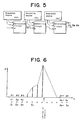
- fuzzy information will be explained with reference to Fig. 6.
- Elements of fuzzy information are denoted by x, and it is assumed that there are discrete values x 1 , x 2 , ...x n-1 , x n .
- These elements are output onto a plurality of signal lines l 1 , l 2 , ...l n , respectively, and grades (functional values corresponding to variables) ⁇ 1 , ⁇ 2 , ... ⁇ n corresponding to these elements are represented by analog voltages or current signals appearing on the respective signal lines.
- Equation (1) is transformed into Equation (2), and the latter is adjusted so that the denominator in Equation (2) is 1, thus eliminating the need for division: That is, if K is adjusted so that the denominator is 1, the center of gravity can be obtained from Equation (3):
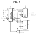
- Fig. 7 is a specific circuit diagram
- voltages ⁇ 1 , ⁇ 2 , ... ⁇ n representative of elements of fuzzy information are led out onto n signal lines l 1 , l 2 , ...l n and then multiplied by the coefficient K in a variable-grade reasoning engine 1 to obtain fuzzy quantities K ⁇ 1 , K ⁇ 2 , ...K ⁇ n , which are input to both a weighted summing circuit 2 and a simple summing circuit 3.
- calculation of Equation (3) is executed to output a voltage signal representative of the center of gravity.
- the simple summing circuit 3 executes calculation of the denominator of Equation (2) and inputs the result of the calculation to a voltage adjusting circuit 4.
- the other input terminal of the voltage adjusting circuit 4 is supplied with a voltage corresponding to the grade 1. Accordingly, in response to the output signal from the voltage adjusting circuit 4, the coefficient K in the variable-grade reasoning engine 1 is adjusted so that the output from the simple summing circuit 3 is 1 at all times.
- a circuit portion of the fuzzy reasoning circuit which is related to electric signals distributed over a plurality of lines l 1 , l 2 , ...l n is controlled so that the output signal from the simple summing circuit 3, which is supplied with the electric signals, is equivalent to 1.
- the membership function circuit is provided with a grade control means to control the grade of the membership function.
- this type of control system if there are two or more converting elements, these elements cannot share one membership function circuit with each other, so that a membership function circuit must be provided for each converting element. The reason for this is that there is no possibility that grade control signals from all the defuzzifiers will be identical to each other.
- the prior art employs an FET as a feedback resistor of an operational amplifier to adjust the gains of the weighted summing circuit 2 and the simple summing circuit 3 so that the output from the simple summing circuit 3 is equivalent to 1.
- the FET since the FET has no satisfactory linear characteristics, the required accuracy cannot be obtained, so that a costly variable-gain amplifier is needed in practice.
- weighting necessitates processing of the reasoning results by using a costly multiplier.
- the weighting process will be explained below with reference to Fig. 8.
- Fig. 8(a) is a block diagram showing the arrangement for weighting, and Fig. 8(b) shows input/output port assignment.
- Inputs INP 1, INP 2, ... are input to a reasoning engine 5 to reason a volumetric efficiency K v (OUT 0) according to rules (not shown).
- an input INP 5 is input to a reasoning engine 6 to reason a water temperature correction factor K w (OUT 1) according to rules (not shown).
- the two reasoning results are input to a multiplier 9 to obtain K v ⁇ K w .
- Fig. 9 shows a system that needs no multiplier.
- a volumetric efficiency K v (OUT 0) is reasoned in a reasoning engine 10, and the result obtained is input to an input port INP 0 to obtain K v -K w in a reasoning engine 12.
- these conventional weighting techniques are unsuitable because of an increased number of rules.
- the present invention arises from our work seeking to provide defuzzifier circuits with relatively simple circuits which are capable of sharing the membership function with other defuzzifiers.
- a defuzzifier circuit comprising: a weighted summing circuit adapted to sum electric signals representative of fuzzy information distributed over a plurality of lines after multiplying said signals by respective values corresponding to the grades of said lines; a simple summing circuit adapted to sum said electric signals without weighting; a constant-current source connected to said simple summing circuit;. and means for equalizing the voltage at the downstream side of summing resistances of said simple summing circuit with the voltage at the downstream side of weighted summing resistances of said weighted summing circuit.
- the invention provides, in a second and alternative aspect thereof, a defuzzifier circuit comprising: a weighted summing circuit adapted to sum electric signals representative of fuzzy information distributed over a plurality of lines after multiplying said signals by respective values corresponding to the grades of said lines; a simple summing circuit adapted to sum said electric signals without weighting; weight signal generating means capable of setting a weight externally; and means for controlling a circuit portion related to said electric signals so that the output of said simple summing circuit takes a value in accordance with the output of said weight signal generating means.
- a defuzzifier circuit comprising: a weighted summing circuit adapted to sum electric signals representative of fuzzy information distributed over a plurality of lines after multiplying said signals by respective values corresponding to the grades of said lines; a simple summing circuit adapted to sum said electric signals without weighting; a constant-current source provided at the downstream side of said simple summing circuit; weight signal generating means capable of setting a weight externally; and a mechanism for equalizing the voltage at the downstream side of summing resistances of said simple summing circuit with the voltage at the downstream side of weighted summing resistances of said weighted summing circuit.
- a weighted summing circuit 2 is connected to fuzzy buses 14 through weighted summing resistances R 1 , R 2 , ..., R i , ...R N .
- a common tgerminal of the weighted summing resistances is connected to a minus terminal of an operational amplifier 15.
- a plus terminal of the operational amplifier 15 is connected to a common terminal of simple summing resistances through a resistance R c .
- a resistance R f is connected between the minus terminal and output terminal of the operational amplifier 15.
- a current i f that flows through the resistance R f is output as a converted current.
- the downstrem side of the weighted summing resistances R i is connected to the downstream side P of the simple summing resistances by the operational amplifier 15.
- the downstream side of the weighted summing resistances R i is herein imaginary-shorted to the downstream side P of the simple summing resistances.
- the weighted summing resistances R 1 to R N are connected to the fuzzy buses 14 and also connected to the resistance R f through respective transistors Q w
- the resistance R are connected to the fuzzy buses 14 and also connected to a constant-current source 16 through respective transistors Q c .
- the constant-current source 16 is connected to the junction point P of the simple summing circuit 3, only a constant current flows through the simple summing circuit 3. Moreover, since the base potential of the transistors Q c of the simple summing circuit 3 is imaginary-shorted to the base potential of the transistors Q w of the weighted summing circuit 2, the potential at the point P is reflected upon the weighted summing circuit 2. For example, when the potential at the point P rises, the current that is supplied to the weighted summing circuit 2 is limited, whereas, when the potential at the point P lowers, the current supplied to the weighted summing circuit 2 increases.
- the current supply is controlled by the constant-current source 16 so that the value of current flowing to the simple summing circuit 3 is 1, the current if flowing to the weighted summing circuit 2 appears as a defuzzified current.
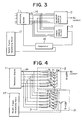
- Fig. 3 is a block diagram of another embodiment of our circuit, in which the same portions or elements as those in Figs. 1 and 2 are denoted by the same reference numerals and description thereof is omitted.
- a comparator 18 is supplied with output signals from the simple summing circuit 3 and a weight signal generating means 17, and the output of the comparator 18 is supplied to the reasoning engine 1.
- the other arrangement of this embodiment is the same as in the embodiment shown in Figs. 1 and 2.
- Fig. 4 is a block diagram of still another embodiment of our circuit.
- a simple summing circuit 3 is connected to fuzzy buses 14 led out from a reasoning engine 1 through respective resistances R and also connected to a constant-current source 16 through transistors Q c .
- a weighted summing circuit 2 is connected to the fuzzy buses 14 through weigting resistances R 1 to R N , which are connected to the respective emitters of transistors Q w .
- the constant-current sourse 16 increases the current value in response to an increase in the weight signal from a weight signal generating circuit 17, resulting in a lowering in the potential at the point P 0 . Since the point P 0 and the point P 1 are imaginary-shorted, the potential at P 1 also lowers, resulting in an increase in the output current. Accordingly, it is possible to obtain a determined value in accordance with the weight signal.
- Fig. 5 is a block diagram of a further embodiment of our circuit.
- this embodiment is an application example in which the present invention is applied to engine control.
- a volumetric efficiency K v K v ⁇ K w ⁇ K a .
- defuzzifier circuits are connected in series to output a correction coefficient K t .
- defuzzifier circuit all have a simplified arrangement and can share the membership function with a plurality of converting mechanisms.
- a weight can be set externally, it is possible to provide a defuzzifier circuit capable of delivering a weighted output with a simple circuit configuration.
Landscapes
- Engineering & Computer Science (AREA)
- Physics & Mathematics (AREA)
- Theoretical Computer Science (AREA)
- Mathematical Physics (AREA)
- Software Systems (AREA)
- General Physics & Mathematics (AREA)
- Computational Mathematics (AREA)
- Biomedical Technology (AREA)
- General Health & Medical Sciences (AREA)
- Fuzzy Systems (AREA)
- Algebra (AREA)
- Artificial Intelligence (AREA)
- Health & Medical Sciences (AREA)
- Data Mining & Analysis (AREA)
- Evolutionary Computation (AREA)
- Molecular Biology (AREA)
- Mathematical Analysis (AREA)
- Mathematical Optimization (AREA)
- Pure & Applied Mathematics (AREA)
- Computing Systems (AREA)
- General Engineering & Computer Science (AREA)
- Automation & Control Theory (AREA)
- Life Sciences & Earth Sciences (AREA)
- Computer Hardware Design (AREA)
- Feedback Control In General (AREA)
Applications Claiming Priority (4)
| Application Number | Priority Date | Filing Date | Title |
|---|---|---|---|
| JP109709/91 | 1991-04-15 | ||
| JP3109709A JP2603164B2 (ja) | 1991-04-15 | 1991-04-15 | デファジィファイア回路 |
| JP131869/91 | 1991-05-07 | ||
| JP3131869A JP2651635B2 (ja) | 1991-05-07 | 1991-05-07 | デファジィファイア回路 |
Publications (2)
| Publication Number | Publication Date |
|---|---|
| EP0509796A2 true EP0509796A2 (de) | 1992-10-21 |
| EP0509796A3 EP0509796A3 (en) | 1993-05-12 |
Family
ID=26449439
Family Applications (1)
| Application Number | Title | Priority Date | Filing Date |
|---|---|---|---|
| EP19920303402 Withdrawn EP0509796A3 (en) | 1991-04-15 | 1992-04-15 | Defuzzifier circuit |
Country Status (2)
| Country | Link |
|---|---|
| US (1) | US5561739A (de) |
| EP (1) | EP0509796A3 (de) |
Cited By (3)
| Publication number | Priority date | Publication date | Assignee | Title |
|---|---|---|---|---|
| EP0600569A1 (de) * | 1992-11-12 | 1994-06-08 | Daimler-Benz Aktiengesellschaft | Verfahren zur Auswertung einer Menge linguistischer Regeln |
| DE19640635A1 (de) * | 1996-10-02 | 1998-04-16 | Harro Prof Dr Kiendl | Verfahren zur Defuzzifizierung für signalverarbeitende Fuzzy-Baueinheiten und Defuzzifizierungseinrichtungen hierfür |
| US9760533B2 (en) | 2014-08-14 | 2017-09-12 | The Regents On The University Of Michigan | Floating-gate transistor array for performing weighted sum computation |
Families Citing this family (4)
| Publication number | Priority date | Publication date | Assignee | Title |
|---|---|---|---|---|
| DE4410834C1 (de) * | 1994-03-29 | 1995-07-27 | Mathematik Und Datenverarbeitu | Analoger Fuzzy-Logik-Controller |
| JP3014618B2 (ja) * | 1994-06-03 | 2000-02-28 | コリア テレコミュニケーション オーソリティ | ファジー演算装置 |
| US6245117B1 (en) | 1998-08-07 | 2001-06-12 | Ipposha Oil Industries Co., Ltd. | Modifier of cellulose fibers and modification method of cellulose fibers |
| US6763337B1 (en) * | 1999-03-05 | 2004-07-13 | Lockheed Martin Corporation | Weighted wedge defuzzification for conceptual system design evaluation |
Family Cites Families (13)
| Publication number | Priority date | Publication date | Assignee | Title |
|---|---|---|---|---|
| JP2693167B2 (ja) * | 1988-03-04 | 1997-12-24 | 新日本無線株式会社 | スイープ・タイプのファジィ・コンピュータ,スイープ・タイプのファジィ・コントローラ,ならびにこれらで用いられるメンバーシップ関数回路,スイープ・タイプのメンバーシップ関数出力回路,デファジファィア,重心決定回路およびα演算回路 |
| JP2779173B2 (ja) * | 1988-08-19 | 1998-07-23 | 科学技術振興事業団 | グレード・コントローラブル・メンバーシップ関数回路,グレード・コントローラブル・メンバーシップ関数発生回路,これらを用いたファジィ・コンピュータおよびファジィ・コントローラ |
| JP2769163B2 (ja) * | 1988-08-19 | 1998-06-25 | 科学技術振興事業団 | 重心決定回路 |
| US5167005A (en) * | 1988-08-19 | 1992-11-24 | Research Development Corporation Of Japan | Fuzzy computer |
| US5179625A (en) * | 1988-09-26 | 1993-01-12 | Omron Tateisi Electronics Co. | Fuzzy inference system having a dominant rule detection unit |
| JP2775447B2 (ja) * | 1988-12-07 | 1998-07-16 | アプト・インスツルメンツ株式会社 | 真理値フローによる処理装置 |
| JPH02155045A (ja) * | 1988-12-07 | 1990-06-14 | Aputo Instr Kk | 真理値コンバータ |
| US5228111A (en) * | 1989-02-09 | 1993-07-13 | G.D.S. Co., Ltd. | Fuzzy signal defuzzifier using charged coupled devices |
| JPH02208787A (ja) * | 1989-02-09 | 1990-08-20 | Yasuo Nagazumi | フアジイ演算回路および該回路を用いたファジイ計算機 |
| US5046019A (en) * | 1989-10-13 | 1991-09-03 | Chip Supply, Inc. | Fuzzy data comparator with neural network postprocessor |
| US5267348A (en) * | 1990-03-09 | 1993-11-30 | Hitachi, Ltd. | Method and system for evaluating and modifying fuzzy knowledge |
| US5245695A (en) * | 1991-06-12 | 1993-09-14 | American Neuralogix Inc. | Fuzzy microcontroller |
| US5259063A (en) * | 1991-09-18 | 1993-11-02 | The United States Of America As Represented By The Administrator, National Aeronautics And Space Administration | Reconfigurable fuzzy cell |
-
1992
- 1992-04-15 EP EP19920303402 patent/EP0509796A3/en not_active Withdrawn
-
1994
- 1994-08-17 US US08/292,292 patent/US5561739A/en not_active Expired - Fee Related
Cited By (5)
| Publication number | Priority date | Publication date | Assignee | Title |
|---|---|---|---|---|
| EP0600569A1 (de) * | 1992-11-12 | 1994-06-08 | Daimler-Benz Aktiengesellschaft | Verfahren zur Auswertung einer Menge linguistischer Regeln |
| US5625754A (en) * | 1992-11-12 | 1997-04-29 | Daimler-Benz Ag | Method of evaluating a set of linguistic rules |
| DE19640635A1 (de) * | 1996-10-02 | 1998-04-16 | Harro Prof Dr Kiendl | Verfahren zur Defuzzifizierung für signalverarbeitende Fuzzy-Baueinheiten und Defuzzifizierungseinrichtungen hierfür |
| DE19640635C2 (de) * | 1996-10-02 | 1999-02-11 | Harro Prof Dr Kiendl | Verfahren zur Defuzzifizierung für signalverarbeitende Fuzzy-Baueinheiten |
| US9760533B2 (en) | 2014-08-14 | 2017-09-12 | The Regents On The University Of Michigan | Floating-gate transistor array for performing weighted sum computation |
Also Published As
| Publication number | Publication date |
|---|---|
| US5561739A (en) | 1996-10-01 |
| EP0509796A3 (en) | 1993-05-12 |
Similar Documents
| Publication | Publication Date | Title |
|---|---|---|
| US4837725A (en) | Fuzzy membership function circuit | |
| US4356450A (en) | Offset compensating circuit for operational amplifier | |
| US5351010A (en) | Resistance ratio measurement utilizing measuring currents of opposite plural direction | |
| EP0509796A2 (de) | Schaltung zur Aufhebung der Verschwommenheit | |
| US5122945A (en) | Voltage controlled preload | |
| US4631522A (en) | Method and circuit for compensation of a multiplying digital-to-analog converter | |
| EP0029700B1 (de) | Analog-Digital-Umsetzer | |
| US5731696A (en) | Voltage reference circuit with programmable thermal coefficient | |
| US5013996A (en) | Voltage regulator for a generator | |
| USRE36421E (en) | Fuzzy controller for selecting an input signal | |
| US5631546A (en) | Power supply for generating at least two regulated interdependent supply voltages | |
| GB2143347A (en) | Current regulation of an electromagnetic load | |
| US4635180A (en) | Device for controlling and regulating current flowing through an electromagnetic consumer, particularly for use in connection with an internal combustion engine | |
| JP2603164B2 (ja) | デファジィファイア回路 | |
| US2840777A (en) | Direct current power source | |
| US4562523A (en) | Power supply | |
| CA1241094A (en) | Mid-value circuit and control system | |
| JPH086652A (ja) | 電子負荷装置 | |
| SU959054A1 (ru) | Способ управлени параллельно включенными стабилизаторами посто нного напр жени | |
| JP2651635B2 (ja) | デファジィファイア回路 | |
| EP0502701A2 (de) | Schaltung zum Gebrauch in Vebindung mit Signalen welche unscharfe Information darstellen | |
| CN116755655B (zh) | 一种乘除法运算器 | |
| JP2535323B2 (ja) | 負荷電流制御装置 | |
| SU1026124A1 (ru) | Стабилизатор переменного сигнала | |
| RU2065619C1 (ru) | Система вторичного электропитания |
Legal Events
| Date | Code | Title | Description |
|---|---|---|---|
| PUAI | Public reference made under article 153(3) epc to a published international application that has entered the european phase |
Free format text: ORIGINAL CODE: 0009012 |
|
| AK | Designated contracting states |
Kind code of ref document: A2 Designated state(s): DE FR GB IT |
|
| PUAL | Search report despatched |
Free format text: ORIGINAL CODE: 0009013 |
|
| AK | Designated contracting states |
Kind code of ref document: A3 Designated state(s): DE FR GB IT |
|
| 17P | Request for examination filed |
Effective date: 19930908 |
|
| STAA | Information on the status of an ep patent application or granted ep patent |
Free format text: STATUS: THE APPLICATION IS DEEMED TO BE WITHDRAWN |
|
| 18D | Application deemed to be withdrawn |
Effective date: 19951101 |