EP0509628A1 - Magnetostrictive alloys, preparation and uses - Google Patents
Magnetostrictive alloys, preparation and uses Download PDFInfo
- Publication number
- EP0509628A1 EP0509628A1 EP92300980A EP92300980A EP0509628A1 EP 0509628 A1 EP0509628 A1 EP 0509628A1 EP 92300980 A EP92300980 A EP 92300980A EP 92300980 A EP92300980 A EP 92300980A EP 0509628 A1 EP0509628 A1 EP 0509628A1
- Authority
- EP
- European Patent Office
- Prior art keywords
- alloy
- magnetostrictive
- mold
- magnetostriction
- mould
- Prior art date
- Legal status (The legal status is an assumption and is not a legal conclusion. Google has not performed a legal analysis and makes no representation as to the accuracy of the status listed.)
- Granted
Links
Images


Classifications
-
- H—ELECTRICITY
- H01—ELECTRIC ELEMENTS
- H01F—MAGNETS; INDUCTANCES; TRANSFORMERS; SELECTION OF MATERIALS FOR THEIR MAGNETIC PROPERTIES
- H01F1/00—Magnets or magnetic bodies characterised by the magnetic materials therefor; Selection of materials for their magnetic properties
- H01F1/01—Magnets or magnetic bodies characterised by the magnetic materials therefor; Selection of materials for their magnetic properties of inorganic materials
- H01F1/03—Magnets or magnetic bodies characterised by the magnetic materials therefor; Selection of materials for their magnetic properties of inorganic materials characterised by their coercivity
- H01F1/0302—Magnets or magnetic bodies characterised by the magnetic materials therefor; Selection of materials for their magnetic properties of inorganic materials characterised by their coercivity characterised by unspecified or heterogeneous hardness or specially adapted for magnetic hardness transitions
- H01F1/0306—Metals or alloys, e.g. LAVES phase alloys of the MgCu2-type
-
- H—ELECTRICITY
- H10—SEMICONDUCTOR DEVICES; ELECTRIC SOLID-STATE DEVICES NOT OTHERWISE PROVIDED FOR
- H10N—ELECTRIC SOLID-STATE DEVICES NOT OTHERWISE PROVIDED FOR
- H10N35/00—Magnetostrictive devices
- H10N35/80—Constructional details
- H10N35/85—Magnetostrictive active materials
Definitions
- the present invention relates to a magnetostrictive alloy having a high coefficient of magnetostriction, and more particularly to a magnetostrictive alloy which is suitable for use as a primary element of a device designed to convert magnetic energy to mechanical energy and vice versa.
- the present invention also relates to methods of producing the magnetostrictive alloy mentioned above.
- Magnetic materials are deformed by magnetostriction when an external magnetic field is impressed. Applying this effect, magnetic-mechanical displacement conversion devices (hereinafter referred to as “devices”) have been developed.
- vibration field these devices are, magnetostriction vibrators, applicable to speakers, sonars, ultrasonic delay lines, ultrasonic processing machines, vibration-preventive and vibration-isolating mechanisms, and the like.
- mechanical application field they are used in displacement control actuators, precision positioning mechanisms, control valves, mechanical switches, micro pumps, printer heads, and the like.
- sensors they are also used in pressure sensors, knock sensors, sound pressure sensors, and the like. In addition, they are also applicable to devices using elastic surface waves.
- magnetostriction materials are extremely useful in the industrial field.
- magnetostriction materials used for these devices Ni-base alloys, Fe-Co alloys and ferrite materials are known. Recently, rare earth-iron intermetallic compounds of the Laves type (expressed by the general expression AB2 having the cubic crystal structure MgCu2, and having a saturated magnetostriction of 1000 x 10 ⁇ 6 or more) having been reported (Japanese Patent Publication TOKKU-KO-SHO No. 61-33892).
- the compounds of the present invention have a greater absolute quantity of magnetostriction than the conventional magnetostriction materials mentioned above.
- magnetostrictive alloy rods have been manufactured by the floating zone refining method (Japanese Patent Disclosure TOKKU-KAI-SHO No. 62-109946 or US Patent No. 4,609,402) and the improved type Bridgman method (Japanese Patent Disclosure TOKKU-KAI-SHO No. 63-2424422 or European Open Patent No. 282059) to form a magnetostrictive alloy having a large magnetostriction.
- Such methods form the magnetostriction alloy into parts that are relatively small in diameter, only rod shaped and at a high manufacturing cost. Such methods are, therefore, not adequate for mass production.
- such materials should exhibit large magnetostriction in a magnetic field as low as several kOe.
- magnetostriction alloys having satisfactory magnetostrictive characteristics consisting of the rare earth-iron system alloys have not yet been developed.
- the present invention has been made in view of the circumstances described above. It is an object of the present invention to provide magnetostrictive alloys that show large magnetostriction even in a low magnetic field.
- a magnetostrictive alloy comprised of a composition whose atomic ratio is expressed by: Tb x R y Dy 1-x-y (Fe 1-z Mn z ) w where x+y ⁇ 1, 0.005 ⁇ y ⁇ 0.9, 0.005 ⁇ z ⁇ 0.5, 1.5 ⁇ W ⁇ 2.5 and R is at least one element selected from the group consisting of Y, Ln, Ce, Pr, Nd and Sm.
- the alloy exhibits a value of magnetostriction in excess of 500ppm. It is further preferred that the alloy is comprised of the Laves phase and exhibits magnetostriction in magnetic fields of less than 2 kOe.
- a method of how to form a magnetostrictive alloy of the present invention includes the step of casting the alloy in a heated mold that is provided with a temperature gradient.
- the alloy is solidified in the mold to form a solidified alloy.
- the method preferably includes the step of plastically deforming the solidified alloy by hot working.
- the magnetostrictive alloy according to the first embodiment of the present invention has a composition whose atomic ratio is expressed by Tb x R y Dy 1-x-y (Fe 1-z Mn z ) w the ranges of x, y, z and w as follows: x + y ⁇ 1, 0.005 ⁇ y ⁇ 0.9, 0.005 ⁇ z ⁇ 0.5, 1.5 ⁇ w ⁇ 2.5 and R is at least one element selected from the group consisting of: Y, La, Ce, Pr, Nd and Sm.
- the elements Tb and Dy belong to the lanthanum system, and differ from such 3d transition elements as Fe, Ni and the like, because they have extremely large magnetic anisotropy due to the strong orbital angular momentum of their 4f electrons. Therefore they become the base to display the large magnetostrictive characteristic. Further, the R element is relatively easy to obtain, such as Pr and the like. When expensive Tb and Dy are partially substituted by this R element, then the magnetic anisotropy of these rare earth atoms changes and the magnetostrictive characteristic in the low magnetic field is improved.
- Laves-type intermetallic compounds (Laves phase) with such earth elements as Tb, Dy and R element and these compounds have displayed a remarkably high magnetostrictive characteristic. Further, if Mn is included for some of the Fe, the magnetostriction anisotropy of rare earth elements changes and these Laves-type intermetallic compounds show excellent magnetic characteristics not only in a high magnetic field but also in a low magnetic field.
- Tb, R, Dy, Fe and Mn of the magnetostrictive alloy involved in the first embodiment are specified by the ratio of atoms x, y, z and w.
- the reason for setting x+y ⁇ 1 is because Dy is an essential element for the first embodiment.
- Tb is effective to produce the magnetostrictive property in an amount of 0.50 or more. If, however, x is more than 0.5 the magnetostrictive property is decreased. It is, therefore, preferred that the value of x be 0.5 or less.
- This 1-3 phase is a crystal structure in the ratio of rare earth and iron at 1:3, and has an extremely small magnetostriction. Both of these factors lead to deterioration of the magnetostriction characteristic.
- the substitution in the formula Fe 1-a T a (a indicates the substitution quantity) should be in the range of from 0 ⁇ a ⁇ 0.5.
- Mn is at least one of the elements selected from the group consisting of: Mg, Al, Ga, Ru, Rh, Pd, Ag, Cd, In, Sn, Sb, Os, Ir, Pt, Au, Hg, T1 and Pb.
- M' is at least one of the elements selected from the group consisting of: Mg, Al, Ga, Ru, Rh, Pd, Ag, Cd, In, Sn, Sb, Os, Ir, Pt, Au, Hg, T1 and Pb.
- the substitution in the formula Fe 1-z-zz Mn z M'n zz should be in the range of from 0 ⁇ zz ⁇ 0.2.
- the magnetostrictive alloy involved in the first embodiment is oriented preferentially in one of the specific crystallographic directions ⁇ 110 ⁇ or ⁇ 111 ⁇ of the cubic system, the magnetostrictive characteristic in this orientation is larger than that in other directions.
- the magnetostrictive alloy RE Fe p (1.5 ⁇ p ⁇ 2.5) forms the abovementioned Laves type intermetallic compound.
- the rare earth element (RE) is selected from the group consisting of the elements: Y, La, Ce, Pr, Nd, Pm, Sm, Eu, Gd, Tb, Dy, Ho, Er, Tm, Yb and Lu. Such an alloy and has been grown in the ⁇ 110 ⁇ crystal direction.
- both single and multiple crystals of this rare earth-iron magnetostriction alloy readily grow in the ⁇ 110 ⁇ crystal direction. Therefore, when these alloys are formed in the shape of a rod to use them in devices, if they are manufactured by having them grow in the ⁇ 110 ⁇ direction using the floating zone refining method (i.e. formed gradually by moving the heating zone) or by casting with a temperature gradient, the manufacturing time is shortened. In case of the floating zone refining, it is possible to substantially reduce the number of heating cycles.
- the magnetostriction alloy RE Fe p (1.5 ⁇ p ⁇ 2.5) manufactured with the crystal direction arranged in the ⁇ 110 ⁇ direction displays high magnetostriction characteristics even in a low magnetic field. When the atomic ratio p is less than 1.5, a rare earth rich phase increases, and when p is more than 2.5, the Laves phase decreases. Both of these conditions lead to deterioration of the magnetostriction characteristic.
- the preferential crystal growth in the direction ⁇ 110 ⁇ can be promoted because the Fe element is substituted by Mn in atomic ratio c. If the atomic ratio c is less than 0.005, this effect may not be obtained, while if it exceeds 0.5, the Curie temperature drops and the magnetostriction characteristic is deteriorated.
- T elements Co, Ni
- M' elements Mg, Al, Ga, Ru, Rh, Pd, Ag, Cd, In, Sn, Sb, Os, Ir, Pt, Au, Hg, Tl and Pb
- the crystal having the ⁇ 110 ⁇ easy magnetizing axis is grown in the ⁇ 110 ⁇ direction.
- the crystal forms in the shape of a sheet.
- the structure of the crystal may also be arranged in the direction of ⁇ 111 ⁇ , which is perpendicular to the ⁇ 110 ⁇ direction.
- portions of the alloy crystallized in the ⁇ 111 ⁇ direction are obtainable from an alloy grown in the ⁇ 110 ⁇ direction.
- the easy magnetizing axis in the ⁇ 111 ⁇ direction is desirable from the viewpoint of magnetostriction characteristics.
- the third embodiment of the present invention includes the elements of Fe and Mn as shown by the formula RE (Fe 1-q-r Mn q M r ) s where RE is the same as in the second embodiment and M is at least one of the group consisting of C, Mg, Al, Si, Ca, Zr, Y, Ga and B and 0.005 ⁇ q ⁇ 0.5, 0.005 ⁇ r ⁇ 0.2, 1.90 ⁇ s ⁇ 2.10.
- the third embodiment has the same rare earth-iron Laves phase as described above. A portion of the element Fe of this magnetostrictive alloy has been partially substituted by the element Mn.
- the separation of the 1-3 phase that could not be avoided when forming Laves type intermetallic compounds, is suppressed to 5 volume % or less.
- Such alloys are immediately usable without performing lengthy homogenizing treatments to eliminate undesirable segregation of other undesirable phases.
- the element M has the effect of suppressing the 1-3 phase preferentially and assists the function of Mn described above. Further, it is also possible to include M' elements within the range of the same atomic ratio as M elements.
- the atomic ratio q is less than 0.005, the 1-3 separation suppression effect is not obtained, while if it is above 0.5; the Curie temperature drops and the magnetostriction characteristics deteriorate. Further, if the atomic ratio r is less than 0.005, the effect of M elements described above is not obtained, while if it is above 0.2, the magnetostriction effect decreases.
- the atomic ratio s is less than 1.9, the 1-3 phase is scarcely present even when Mn is not contained but a rare earth rich phase increases. If it is above 2.1, the 1-3 phase suppressing effect of Mn is not obtained.
- M' elements within a range as described above without impairing the magnetostriction characteristics.
- the third embodiment when the third embodiment is arranged mainly in the directions of ⁇ 110 ⁇ and ⁇ 111 ⁇ the magnetostriction characteristic is better than that in other directions.
- this alloy is used as the seed alloy in crystal growing techniques it is easy to perform the unidirectional solidification that orients the crystal direction during the manufacture of single crystals.
- the preferential crystal growth in the direction of ⁇ 110 ⁇ is defined as follows.
- the peak intensity of the diffracted beam from the ⁇ 220 ⁇ facet is described as I220.
- the maximum peak intensity of the ⁇ 311 ⁇ diffraction is described as I311.
- the preferential crystal growth in the direction of ⁇ 110 ⁇ is defined as the ratio of I220 to I311.
- Px I220/I311 ⁇ 1
- the preferential crystal growth in the direction of ⁇ 111 ⁇ is defined as follows.
- the peak intensity of the diffracted beam from the ⁇ 222 ⁇ facet is described as I222.
- the maximum peak intensity of the ⁇ 311 ⁇ diffraction is described as I311. then the preferential crystal growth in the direction of ⁇ 111 ⁇ (shown as Px) is defined as the ratio of I222 to I311.
- Px I222/I311 ⁇ 1
- the invention further includes a method of making a magnetostrictive alloy.
- the method which will be described in detail below generally involves the casting of a material for a magnetostrictive alloy in a heated mold having temperature gradient.
- the rare earth-iron system Laves type intermetallic compounds are preferable. Such compounds are expressed by the formula: RE Fe x where RE is at least one of the rare earth elements, which are La, Ce, Pr, Nd, Pm, Sm, Eu, Gd, Tb, Dy, Ho, Er, Tm, Yb and Lu.
- R element is a combination of more than 2 kinds of rare earth elements
- use of Tb-Dy, Tb-Ho, Tb-Pr, Sm-Yb, Td-Dy-Ho, Tb-Dy-Pr, Tb-Pr-Ho and the like is desirable.
- Fe may be substituted partially by Mn.
- Fe may be partially substituted by Ni, Mg, Al, Ga, Zn, V, Zr, Hf, Ti, Nb, Cu, Ag, Sn, Mo, Cr, Ta, Pd, In, Sb, Ir, Pt, Au, Pb, W, Si, B and the like in addition to Co and Mn.
- Quantities of elements for substituting Fe should, however, be limited to about 50 at % including that of Mn. If this limit is exceeded, a deterioration of characteristics including a decrease in magnetostriction may occur.
- the atomic ratio X of RE element and Fe is 1.5 ⁇ x ⁇ 2.5. This is because sufficient magnetostriction cannot be obtained if this ratio is below 1.5 or over 2.5.
- the most desirable range is 1.7 ⁇ x ⁇ 2.2. A method of forming such a material is set out below.
- a rare earth and Fe are blended at the prescribed atomic ratio and Co and Mn may be added as desired. These materials are dissolved by a high frequency induction melting method. Ingots having a uniform crystalline form and a desired crystalline alignment can be produced by casting the molten alloys in a heated mold with temperature gradient. This is because the crystal nucleates and grows from the low temperature part of the melt. The preferential crystal growth is directed toward the high temperature portion of the melt and the crystal growing directions become ordered. On the other hand, if cast in a mold heated without a temperature gradient, as is done in the prior art, the many crystals began to be produced on the whole surface of the mold and the crystals grow in random directions. Therefore the crystal directions in such cast materials could not be controlled.
- the magnetostrictive material can be formed into a desired shape.
- Mold 1 is equipped with heater 2 to heat its sides and it further includes cooling plate 3 at the bottom.
- the direction of pouring molten material into the mold is shown by the arrow.
- mold 4 has cooling plate 5 at the bottom.
- the cool end of the mold has an opening 6a contacting cooling plate 5.
- the mold is heated with a temperature gradient provided with the cooling plate 5 at a temperature lower than the sides of the mold.
- Molten alloy is poured into the mold and initial crystals are produced in random directions from the cooling end 5 in the opening 6a. When these initial crystals grow, the crystals growing in different directions negate each other and an alloy of which crystal directions grown in one direction only can be obtained.
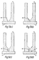
- a mold 4 having an opening 6b in the cooling end with a length shown in figure 5b, or using mold 4 having a bent opening 6c shown in figure 5c results in the selective growth of the crystalline material as it solidifies in such an arrangement. thus the crystal directions are more effectively controlled.
- a mold may have pouring basin 7 at the tip of opening 6d as shown in Figure 5d. The bottom of pouring basin 7 is in contact with cooling plate 5. As there is a temperature gradient between the bottom and the top of pouring basin 7, crystals of a certain size in the uniform crystal direction are formed, the crystal direction is further selected by the opening 6d. As a result, a magnetostrictive material is formed having a well controlled crystal direction.
- ingots cast in the more uniform crystal direction can be obtained by providing a solid crystal oriented in the desired crystalline direction at the colder end of the mold.
- a cooling plate can be provided at the core of a columnar mold with the circumference of the mold sides heated. Using such an arrangement a radially oriented temperature gradient would extend from the central core to the sides of the heated mold. when a magnetostrictive material is cast using such a mold the material solidifies on the central core and grows in a uniform direction toward the sides of the mold. when solidified in such a manner the crystalline material is radially anisotropic.
- Alumina, BN, MgO, CaO carbon, etc. can be used as material for the mold described above. Further, it is desirable to smooth the surface of a mold. If the inner surface of a mold is excessively rough, that part becomes the nucleus for growing crystals.
- the cooling plate material metals having relatively large thermal conductivity such as copper or iron are usable.
- the cooling plate may be water cooled.
- a separating agent such as BN on the inner surface of the mold can be applied as necessary.
- the heating temperature is desirable to be above the eutectic temperature of the magnetostrictive material being cast. This is because crystals begin to grow from the side of the mold below the eutectic temperature and it becomes difficult to make the crystal directions uniform. Further, if heating temperature is too high, a reaction may take place between the mold and magnetostrictive material.
- the desirable temperature is within a range from the eutectic temperature of the magnetostrictive material being cast to a temperature that is 100°C above the melting point of the magnetostrictive material being cast.
- the heater When heating the sides of the mold, the heater may be controlled by dividing it into two or more parts to heat the mold with a temperature gradient provided between the upper and lower parts of the mold. In this case, if the temperature gradient is provided to heat the mold in such a manner that the lower part of the mold is heated to a low temperature while the upper part is heated to a high temperature, the crystals directions of the magnetostrictive material being cast are made more uniform than when the mold was heated with the side temperature kept at a constant level.
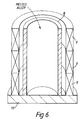
- An example of a mold provided with side heating heaters split into several units is shown in Figure 6. In the example shown in Figure 6, it is possible to split heater 3 for heating the side of mold 8 into three units and provide temperature gradients to 3 stages of the upper part, middle part and lower part at the side. Further, a cooling plate 10 is provided at the bottom of mold 8.
- a desirable heating temperatures is in a range from 600°C to 900°C at the lower part of a mold and a range from 850°C to 1300°C at the upper part.
- An insulator may be installed between such a heater and a mold for the purpose of controlling a temperature gradient.
- magnetostrictive materials it is desirable to perform the dissolution and casting of magnetostrictive materials in an atmosphere of inert gas such as argon, helium or in a vacuum.
- inert gas such as argon, helium or in a vacuum.
- cast ingots may be heat treated for 0.1 to 500 hours at temperatures in a range from 850°C to 1200°C. This heat treatment can reduce magnetic impurity phases, homogenize the alloy and reduce the coercive force of magnetostrictive alloys so treated.
- the magnetostrictive alloys of the present invention are further improved by a plastic deformation process. Since magnetostrictive alloys are normally used in the shapes of wire, rod, etc., the magnetostrictive alloy obtained according to the methods described above can be made into desired shapes without a grinding process. Therefore, the productivity of such processes is high. In addition, since its structure can be made uniform along the direction of plastic deformation, it is possible to make the crystal direction uniform and promote the magnetostrictive characteristic in the formed materials.
- the materials mixed in the prescribed amounts are blended and then dissolved using an ordinary dissolving method such as high frequency induction dissolution, etc., to produce an ingot of rare earth-iron system magnetostrictive alloy.
- an ordinary dissolving method such as high frequency induction dissolution, etc.
- the hot working method may be an extrusion process, drawing, rolling, or the like. Further, the temperature during the plastic deformation must be above 500°C and below the melting point of the ingot. This is because a sufficient plastic deformation cannot be obtained below 500°C and the shape of alloy cannot be maintained at above the melting point of the alloy ingot.
- the desirable temperature range is from 800°C to 1200°C, more practically from 1000°C to 1200°C. Further, wire shaped rods as thin as below 1 mm ⁇ can be formed by performing such hot working repeatedly.
- the magnetostrictive characteristic by performing the heat treatment for 0.1 to 500 hours at 500 to 1100°C after the hot working. It is desirable to perform the hot working and heat treatment in an atmosphere of inert gas such as argon gas, helium gas or in a vacuum.
- inert gas such as argon gas, helium gas or in a vacuum.
- a magnetostrictive alloy having excellent mechanical strength and corrosion resistance can be produced by covering the magnetostrictive alloy with a metal during hot working.
- the covering metal should have a melting temperature higher than the hot working temperature and a sufficient deformation ability at the hot working temperature.
- the metal is preferably selected from the group consisting of: stainless steel, Cu or Cu alloys, Ni or Ni alloys, Ti or Ti alloys.
- the test pieces (10mm x 10mm x 5mm) were prepared for the examples 1-17 of the magnetostriction alloy of the first embodiment of the present invention and the magnetostriction alloys as the comparison examples 1-5 were prepared from conventional rare earth-iron systems as shown in Table 1.
- the alloy ingots were produced by the arc melting method in a water-cooled copper mold covered with argon gas and homogenized to form examples 1-7, 15-17 and the comparison examples 1-5 shown in Table 1.
- the unidirectionally solidified bodies were obtained by the unidirectional solidification method for the example 8-11 and the multi-crystal powders were sintered in a magnetic field to get sintered bodies and furthermore, homogenized for one week at 900°C for the example 12-14. Then, the test pieces in the dimensions described above were obtained by cutting these alloy ingots, unidirectionally solidified bodies and sintered bodies.
- all of the magnetostrictive alloys of the invention have exceptionally high magnetostrictive characteristics (the values of the standardized magnetostrictive characteristics are 8-18) in the low magnetic field than conventional rare earth-iron system magnetostrictive alloys (the values of the standardized magnetostrictive characteristics are 1-5).
- the test pieces from the unidirectionally solidified bodies show exceptionally high magnetostrictive characteristics.
- the unidirectionally solidified bodies arranged in the ⁇ 110 ⁇ or ⁇ 111 ⁇ direction in cubic system were obtained for the test pieces of the examples 8-31 relative to the second embodiment of the present invention.
- Magnetostrictive alloys having random crystal structure were obtained for the comparative examples 6-9.
- Figure 7 shows the crystal direction of the magnetostrictive alloy in the above example 28 observed through X-ray diffraction. It can be seen that the magnetostrictive alloy of example 28 with a large magnetic field magnetostrictive characteristic is oriented in the ⁇ 110 ⁇ direction, observed as the ⁇ 220 ⁇ and ⁇ 440 ⁇ directions which are even number multiples of ⁇ 110 ⁇ .
- the alloy ingots were obtained by the arc melting method for the test pieces of examples 32-36 relative to the third embodiment of the present invention.
- the alloy ingots were also obtained by the arc melting method for the test pieces of comparative example 10-14. They were cut in the dimensions 10 X 10 X 5 mm to form the test pieces. they are shown in Table 3.
- all of the magnetostrictive alloys of the invention show exceptionally higher magnetostrictive characteristics (the value of the standardized magnetostrictive characteristics are 10-18) than conventional rare earth-iron system magnetostrictive alloys (the values of the standardized magnetostrictive characteristics are 10-18) in the low magnetic field.
- test pieces of these examples 32-36 have 5 vol% or less contents of 1-3 phase.
- the pieces of comparative examples have more than 5 vol% of 1-3 phase. They are shown in table by signs of 0, ⁇ and X.
- the homogenizing process to reduce the content of 1-3 phase is unnecessary and such a material can be used immediately after being manufactured.
- Figures 2 and 3 are photomicrographs, taken by SEM (voltage: 25 kv), showing the metal structures of the magnetostrictive alloys of example 32 and comparative example 11, respectively. It can be confirmed that the needle shaped 1-3 phases are much more frequently observed in Figure 3, showing the structure of comparative example 11. The needle shaped 1-3 phase, however, can not be seen in Figure 2 showing the structure of example 32.
- a melted alloy of Tb 0.4 DY 0.6 (Fe 0.9 Mn 0.1 ) 1.93 was obtained using high frequency induction dissolution in an argon atmosphere with the alloy in an alumina crucible.
- the above-mentioned alloy was cast in a mold heated at its side and an alloy ingot was obtained.
- the cross-sectional view showing the shape of the mold used in this example is shown in Figure 4. Heating the side of mold 1 by heater 2 positioned around the side and cooling the bottom surface of the mold by cooling plate 3, a temperature gradient was provided between the top and the bottom of mold 1.
- alumina mold having an inner diameter 40mm for mold 1 and carbon heaters for heaters 2, and the side of mold 1 was heated to 950°C.
- a water cooled copper plate 3 was provided and was the starting point of the crystal growth. After casting, the magnetostrictive ingot was furnace cooled.
- the magnetostrictive ingot was machined to a 8mm cube and its magnetostrictive characteristic in the axial direction of the mold was evaluated at room temperature using a strain gauge.
- the magnetic field was produced with a dipole magnet and magnetostriction ( ⁇ ) in the 2 kOe magnetic field was measured. the result was 800 ppm.
- a magnetostrictive alloy was obtained by casting melted alloy with a mold similar to example 37 under the same conditions without heating the side of the mold. Its magnetostriction was measured like example 27 but a value of 400 ppm was obtained.
- a melted alloy of Tb 0.35 Dy 0.65 (Fe 0.9 Mn 0.1 ) 1.95 was obtained by high frequency induction dissolution in an argon atmosphere using an alumina crucible. The alloy was melted and cast to form ingot using the mold shown in cross section in Figure 6.
- Three split heaters 9 on mold 8 provided three stages of temperature gradient to its side.
- cooling plate 10 was installed at the bottom of the mold.
- the lower part, middle part and upper part of the mold were heated to 800°C, 950°C and 1100°C, respectively. After casting, each of the ingots was cooled at the rate of 5°C/min.
- the magnetostrictive ingot was machined to a cube having 8mm sides.
- An axial magnetostrictive characteristic at room temperature was measured using a strain gauge.
- the magnetic field was produced using a dipole magnet and magnetostriction ( ⁇ ) in the 2 kOe magnetic field was measured. The result was 880 ppm.
- Example 51 to 62 were obtained and measured using a similar method as example 50.
- the heating temperatures, cooling after casting and measured values ( ⁇ ) in same condition (2 kOe) of example 39 are also shown in Table 5.
- a melted alloy of Tb 0.45 Dy 0.55 (Fe 0.9 Mn 0.1 ) 1.96 was obtained using high frequency induction dissolution in an argon atmosphere using an alumina crucible.
- Mold 4 is provided with a narrow opening 6 at the bottom, adjacent cooling plate 5 and heaters 11 along the sides.
- the alumina mold 4 has an inner diameter of 60mm.
- Heaters 11 were carbon heaters which heated the side of mold 4 to 1000°C. After casting, the magnetostrictive ingot was cooled at the rate 5°C/min.
- the magnetostrictive ingot was machined to a 8mm cube and its axial magnetostrictive characteristic was evaluated at room temperature using a strain gauge.
- the magnetic field was produced by a dipole magnet and the magnetostriction ( ⁇ ) in the 2 kOe magnetic field was measured. The result was 950 ppm.
- Mold 12 has cooling plate 13 at its bottom. Further, the side of the mold was not heated but all other conditions were the same as example 50. The magnetostriction of the alloy was measured, and a value of 450 ppm was obtained.
- example 64 to 75 were obtained and measured as similar method as example 63.
- the heating temperature, cooling after casting and measured values ( ⁇ ) in same condition (2 kOe) of example 50 are also shown in Table 6.
- the mold was heated by 3 split carbon heaters similar to that shown in Figure 7.
- a melted alloy of Tb 0.4 Dy 0.6 (Fe 0.9 Mn 0.1 ) 1.93 was obtained by high frequency induction dissolution in an argon atmosphere using a BN crucible.
- the melted alloy was cast in a 30mm diameter mold heated to 1100°C by a carbon heater, and cooled in a furnace.
- the ingot of example 76 was obtained.
- a water cooled copper plate was provided to start the crystal growth.
- the alloy ingot was processed according to the hot extrusion method at a temperature 1050°C and extruding pressure 4 ton/cm2. A magnetostrictive alloy rod 8mm in diameter was obtained.
- the hot extrusion apparatus is shown in Fig. 9.
- the ingot 21 was pressed and formed into a rod 22 at the noted temperature provided by heaters 23 and formed into the rod by dies 24.
- the magnetostrictive alloy rod was machined to a 6mm cube and its magnetostrictive characteristic in the extruded direction and the right angle direction were evaluated at room temperature using a strain gauge.
- the magnetic field was produced with a dipole magnet and magnetostriction ( ⁇ ) in the 2kOe magnetic field was measured.
- the results of a value of 1000 ppm in the extruding direction and a value of 400 ppm in the right angle direction were measured.
- An anisotropic alloy rod was obtained according to the invention.
- a magnetostrictive alloy rod having the same composition produced according to a grinding process without performing the hot extrusion process was also evaluated.
- the magnetostrictive characteristic of this rod was a value of 800 ppm in the extrusion direction and 700 ppm in the right angle direction, and the anisotropy was small.
- a melted alloy of Tb 0.5 Dy 0.5 (Fe 0.9 Mn 0.1 ) 1.95 was obtained by high frequency induction dissolution in an argon atmosphere using a BN crucible.
- a stainless steel covered alloy ingot was obtained.
- a water-cooled cooper plate was used as a cooling plate on which to start the crystal growth.
- the stainless steel covered magnetostrictive alloy ingot was processed by the hot extruding at a working temperature 1050°C and extruding pressure 4 ton/cm2 using the equipment shown in Figure 10.
- a stainless steel covered magnetostrictive alloy rod 8mm in diameter was obtained.
- the ingot 25 was pressed and formed into a rod 27 with heaters 3 providing the elevated temperature and dies 4 creating the forming pressure.
- This stainless steel covered super magnetostrictive alloy rod was processed to a 6 mm cube and the magnetostrictive characteristic in the extruding (axial) direction and the right angle direction was evaluated at a room temperature using a strain gauge.
- the magnetic field was produced with a dipole magnet and the magnetostriction ( ⁇ ) in the 2kOe magnetic field was measured.
- the magnetostrictive characteristic obtained was 980 ppm in the extruding axial direction and 390 ppm in the right angle direction.
Abstract
Description
- The present invention relates to a magnetostrictive alloy having a high coefficient of magnetostriction, and more particularly to a magnetostrictive alloy which is suitable for use as a primary element of a device designed to convert magnetic energy to mechanical energy and vice versa.
- The present invention also relates to methods of producing the magnetostrictive alloy mentioned above.
- Magnetic materials are deformed by magnetostriction when an external magnetic field is impressed. Applying this effect, magnetic-mechanical displacement conversion devices (hereinafter referred to as "devices") have been developed. In the vibration field these devices are, magnetostriction vibrators, applicable to speakers, sonars, ultrasonic delay lines, ultrasonic processing machines, vibration-preventive and vibration-isolating mechanisms, and the like. In the mechanical application field they are used in displacement control actuators, precision positioning mechanisms, control valves, mechanical switches, micro pumps, printer heads, and the like. Furthermore, as sensors, they are also used in pressure sensors, knock sensors, sound pressure sensors, and the like. In addition, they are also applicable to devices using elastic surface waves. Thus, magnetostriction materials are extremely useful in the industrial field.
- As magnetostriction materials used for these devices, Ni-base alloys, Fe-Co alloys and ferrite materials are known. Recently, rare earth-iron intermetallic compounds of the Laves type (expressed by the general expression AB₂ having the cubic crystal structure MgCu₂, and having a saturated magnetostriction of 1000 x 10⁻⁶ or more) having been reported (Japanese Patent Publication TOKKU-KO-SHO No. 61-33892). The compounds of the present invention have a greater absolute quantity of magnetostriction than the conventional magnetostriction materials mentioned above.
- Recently the magnetostrictive alloy rods have been manufactured by the floating zone refining method (Japanese Patent Disclosure TOKKU-KAI-SHO No. 62-109946 or US Patent No. 4,609,402) and the improved type Bridgman method (Japanese Patent Disclosure TOKKU-KAI-SHO No. 63-2424422 or European Open Patent No. 282059) to form a magnetostrictive alloy having a large magnetostriction. Such methods, however, form the magnetostriction alloy into parts that are relatively small in diameter, only rod shaped and at a high manufacturing cost. Such methods are, therefore, not adequate for mass production.
- Moreover, to be practically useful such materials should exhibit large magnetostriction in a magnetic field as low as several kOe. In such a low magnetic field, magnetostriction alloys having satisfactory magnetostrictive characteristics consisting of the rare earth-iron system alloys have not yet been developed.
- The present invention has been made in view of the circumstances described above. It is an object of the present invention to provide magnetostrictive alloys that show large magnetostriction even in a low magnetic field.
- It is a further object of the present invention to provide a method of making the magnetostrictive alloys mentioned above.
- These, and other objects of the invention are achieved by means of the present invention. According to the present invention, there is provided a magnetostrictive alloy comprised of a composition whose atomic ratio is expressed by:

where x+y<1,
0.005≦y≦0.9,
0.005≦z≦0.5,
1.5≦W≦2.5 and
R is at least one element selected from the group consisting of Y, Ln, Ce, Pr, Nd and Sm. Preferably, the alloy exhibits a value of magnetostriction in excess of 500ppm. It is further preferred that the alloy is comprised of the Laves phase and exhibits magnetostriction in magnetic fields of less than 2 kOe. - According to the present invention, there is provided a method of how to form a magnetostrictive alloy of the present invention. The method includes the step of casting the alloy in a heated mold that is provided with a temperature gradient. The alloy is solidified in the mold to form a solidified alloy. The method preferably includes the step of plastically deforming the solidified alloy by hot working.
- These and other objects and advantages of this invention will become more apparent and more readily appreciated from the following detailed description of the presently preferred exemplary embodiments of the invention taken in conjunction with the accompanying drawings wherein:
- Fig. 1 is a graph showing the X-ray patterns of the magnetostrictive alloy of example 28 including the present invention.
- Fig. 2 is a photomicrograph showing the structure of the magnetostrictive alloy of example 32 including the present invention.
- Fig. 3 is a photomicrograph showing the structure of the magnetostrictive alloy of the comparative example 11.
- Fig. 4 to 7, are cross-sectional views of the molds used in the examples of the second embodiment of the invention.
- Fig. 8 is a cross-sectional view of the mold used in the comparative example 17.
- Fig. 9 and Fig. 10 are cross-sectional views of the mold used in the examples of the third embodiment of the invention.
- The magnetostrictive alloy according to the first embodiment of the present invention has a composition whose atomic ratio is expressed by

the ranges of x, y, z and w as follows:
x + y < 1,
0.005 ≦ y ≦ 0.9,
0.005 ≦ z ≦ 0.5,
1.5 ≦ w ≦ 2.5
and R is at least one element selected from the group consisting of: Y, La, Ce, Pr, Nd and Sm. The elements Tb and Dy belong to the lanthanum system, and differ from such 3d transition elements as Fe, Ni and the like, because they have extremely large magnetic anisotropy due to the strong orbital angular momentum of their 4f electrons. Therefore they become the base to display the large magnetostrictive characteristic. Further, the R element is relatively easy to obtain, such as Pr and the like. When expensive Tb and Dy are partially substituted by this R element, then the magnetic anisotropy of these rare earth atoms changes and the magnetostrictive characteristic in the low magnetic field is improved. - Fe forms Laves-type intermetallic compounds (Laves phase) with such earth elements as Tb, Dy and R element and these compounds have displayed a remarkably high magnetostrictive characteristic. Further, if Mn is included for some of the Fe, the magnetostriction anisotropy of rare earth elements changes and these Laves-type intermetallic compounds show excellent magnetic characteristics not only in a high magnetic field but also in a low magnetic field.
- The elements of Tb, R, Dy, Fe and Mn of the magnetostrictive alloy involved in the first embodiment are specified by the ratio of atoms x, y, z and w. The reason for setting x+y<1 is because Dy is an essential element for the first embodiment. Tb is effective to produce the magnetostrictive property in an amount of 0.50 or more. If, however, x is more than 0.5 the magnetostrictive property is decreased. It is, therefore, preferred that the value of x be 0.5 or less. Further, if y is less than 0.005, the influence of an R atom on the magnetic anisotropy described above becomes insufficient, while if it is more than 0.9, the Laves phase which seems to correlate with improved magnetostriction characteristics decreases and an undesirable 1-3 phase is formed. This 1-3 phase is a crystal structure in the ratio of rare earth and iron at 1:3, and has an extremely small magnetostriction. Both of these factors lead to deterioration of the magnetostriction characteristic.
- On the other hand, if z is less than 0.005, the influence of Mn on the above-mentioned magnetic anisotropy becomes insufficient, while if z is more than 0.5, the Curie temperature drops. Both of these factors lead to deterioration of the magnetostriction characteristic. Furthermore, if w is less than 1.5 or more than 2.5, the Laves phase, which should become the primary phase, is decreased and the magnetostriction characteristic drops.
- It is also possible to substitute part of Fe with T element (T=Co, Ni) to improve the corrosion resistance of this magnetostriction alloy. However, excessive substitution results in a drop of the Curie temperature and deterioration of the magnetostriction characteristic. Therefore, the substitution in the formula Fe1-aTa (a indicates the substitution quantity) should be in the range of from 0 ≦ a ≦ 0.5.
- In addition, to improve the material strength, the saturated magnetostriction and the corrosion resistance of this magnetostriction alloy it is possible to substitute part of Mn with M' element (M' is at least one of the elements selected from the group consisting of: Mg, Al, Ga, Ru, Rh, Pd, Ag, Cd, In, Sn, Sb, Os, Ir, Pt, Au, Hg, T1 and Pb). However, if the substitution quantity is excessive, the magnetostriction characteristic is deteriorated. Therefore, the substitution in the formula Fe1-z-zz MnzM'nzz (zz indicates the substitution quantity) should be in the range of from 0 ≦ zz ≦ 0.2.
- If the magnetostrictive alloy involved in the first embodiment is oriented preferentially in one of the specific crystallographic directions 〈110〉 or 〈111〉 of the cubic system, the magnetostrictive characteristic in this orientation is larger than that in other directions.
- In the second embodiment involved in the present invention, the magnetostrictive alloy RE Fep (1.5 ≦ p ≦ 2.5) forms the abovementioned Laves type intermetallic compound. The rare earth element (RE) is selected from the group consisting of the elements: Y, La, Ce, Pr, Nd, Pm, Sm, Eu, Gd, Tb, Dy, Ho, Er, Tm, Yb and Lu. Such an alloy and has been grown in the 〈110〉 crystal direction.
- Both single and multiple crystals of this rare earth-iron magnetostriction alloy readily grow in the 〈110〉 crystal direction. Therefore, when these alloys are formed in the shape of a rod to use them in devices, if they are manufactured by having them grow in the 〈110〉 direction using the floating zone refining method (i.e. formed gradually by moving the heating zone) or by casting with a temperature gradient, the manufacturing time is shortened. In case of the floating zone refining, it is possible to substantially reduce the number of heating cycles. The magnetostriction alloy RE Fep (1.5 ≦ p ≦ 2.5) manufactured with the crystal direction arranged in the 〈110〉 direction displays high magnetostriction characteristics even in a low magnetic field. When the atomic ratio p is less than 1.5, a rare earth rich phase increases, and when p is more than 2.5, the Laves phase decreases. Both of these conditions lead to deterioration of the magnetostriction characteristic.
- In the case of the magnetostriction alloy involved in the second embodiment including the element of Fe as shown by the formula RE (Fe1-cMnc)p (1.5 ≦ p ≦ 2.5, 0.005 ≦ c ≦ 0.5), the preferential crystal growth in the direction 〈110〉 can be promoted because the Fe element is substituted by Mn in atomic ratio c. If the atomic ratio c is less than 0.005, this effect may not be obtained, while if it exceeds 0.5, the Curie temperature drops and the magnetostriction characteristic is deteriorated.
- The magnetostriction alloy of the second embodiment can obtain the same effects of the first embodiment if at least one of T elements (T=Co, Ni) or M' elements (Mg, Al, Ga, Ru, Rh, Pd, Ag, Cd, In, Sn, Sb, Os, Ir, Pt, Au, Hg, Tl and Pb) are included in the same substitution quantity.
- Moreover, if the easy magnetizing axis and the crystal axis are in the same direction, excellent magnetostriction is obtained, especially in a low magnetic field. Therefore it is desirable that the crystal having the 〈110〉 easy magnetizing axis is grown in the 〈110〉 direction. When the crystal is grown in the 〈110〉 direction, the crystal forms in the shape of a sheet. In such a case, the structure of the crystal may also be arranged in the direction of 〈111〉, which is perpendicular to the 〈110〉 direction. Thus portions of the alloy crystallized in the 〈111〉 direction are obtainable from an alloy grown in the 〈110〉 direction. In this case, the easy magnetizing axis in the 〈111〉 direction is desirable from the viewpoint of magnetostriction characteristics.
- The third embodiment of the present invention includes the elements of Fe and Mn as shown by the formula RE (Fe1-q-rMnqMr)s where RE is the same as in the second embodiment and M is at least one of the group consisting of C, Mg, Al, Si, Ca, Zr, Y, Ga and B and 0.005 ≦ q ≦ 0.5, 0.005 ≦ r ≦ 0.2, 1.90 ≦ s ≦ 2.10. The third embodiment has the same rare earth-iron Laves phase as described above. A portion of the element Fe of this magnetostrictive alloy has been partially substituted by the element Mn. In this composition the separation of the 1-3 phase, that could not be avoided when forming Laves type intermetallic compounds, is suppressed to 5 volume % or less. Such alloys are immediately usable without performing lengthy homogenizing treatments to eliminate undesirable segregation of other undesirable phases. The element M has the effect of suppressing the 1-3 phase preferentially and assists the function of Mn described above. Further, it is also possible to include M' elements within the range of the same atomic ratio as M elements.
- If the atomic ratio q is less than 0.005, the 1-3 separation suppression effect is not obtained, while if it is above 0.5; the Curie temperature drops and the magnetostriction characteristics deteriorate. Further, if the atomic ratio r is less than 0.005, the effect of M elements described above is not obtained, while if it is above 0.2, the magnetostriction effect decreases.
- Further, if the atomic ratio s is less than 1.9, the 1-3 phase is scarcely present even when Mn is not contained but a rare earth rich phase increases. If it is above 2.1, the 1-3 phase suppressing effect of Mn is not obtained.
- The same effect can be obtained in the third embodiment as in the magnetostriction alloys of the first and second embodiments when T element (T=Co, Ni) in the same substitution quantity is contained. In addition, it is also possible to include the abovementioned M' elements within a range as described above without impairing the magnetostriction characteristics. Like the magnetostriction alloy of the first embodiment, when the third embodiment is arranged mainly in the directions of 〈110〉 and 〈111〉 the magnetostriction characteristic is better than that in other directions.
- If this alloy is used as the seed alloy in crystal growing techniques it is easy to perform the unidirectional solidification that orients the crystal direction during the manufacture of single crystals.
- In the present invention the preferential crystal growth in the direction of 〈110〉 is defined as follows.
- When an X-ray is impinged on the facet of the crystalline material which is perpendicular to the growing axis of the crystalline material, the peak intensity of the diffracted beam from the 〈220〉 facet is described as I₂₂₀. When the x-ray is impinged on powder material of the same composition, the maximum peak intensity of the 〈311〉 diffraction is described as I₃₁₁. Then the preferential crystal growth in the direction of 〈110〉 (shown as Px) is defined as the ratio of I₂₂₀ to I₃₁₁.
- The material arranged in the 〈110〉 direction has the Px value of 1 or more, i.e.,

In the present invention the preferential crystal growth in the direction of 〈111〉 is defined as follows. - When an X-ray is impinged on the facet of the crystalline material which is perpendicular to the growing axis of the crystalline material, the peak intensity of the diffracted beam from the 〈222〉 facet is described as I₂₂₂. When the X-ray is impinged on powder material of the same composition, the maximum peak intensity of the 〈311〉 diffraction is described as I₃₁₁. then the preferential crystal growth in the direction of 〈111〉 (shown as Px) is defined as the ratio of I₂₂₂ to I₃₁₁.
- The material arranged in the 〈111〉 direction has the Px value of 1 or more, i.e.,

When the Px value of a material is Y or more, then it is said that the material is aligned in the direction of 〈111〉. - The invention further includes a method of making a magnetostrictive alloy. The method, which will be described in detail below generally involves the casting of a material for a magnetostrictive alloy in a heated mold having temperature gradient.
- This method can be applicable to not only the materials disclosed above but also other alloys. The rare earth-iron system Laves type intermetallic compounds are preferable. Such compounds are expressed by the formula:
RE Fex
where RE is at least one of the rare earth elements, which are La, Ce, Pr, Nd, Pm, Sm, Eu, Gd, Tb, Dy, Ho, Er, Tm, Yb and Lu. - If R element is a combination of more than 2 kinds of rare earth elements, use of Tb-Dy, Tb-Ho, Tb-Pr, Sm-Yb, Td-Dy-Ho, Tb-Dy-Pr, Tb-Pr-Ho and the like is desirable.
- It is possible to substitute a part of Fe by Co and, in addition, Fe may be substituted partially by Mn.
- Moreover, to improve mechanical strength, corrosion resistance, saturated magnetostriction, etc. of the material, Fe may be partially substituted by Ni, Mg, Al, Ga, Zn, V, Zr, Hf, Ti, Nb, Cu, Ag, Sn, Mo, Cr, Ta, Pd, In, Sb, Ir, Pt, Au, Pb, W, Si, B and the like in addition to Co and Mn. Quantities of elements for substituting Fe should, however, be limited to about 50 at % including that of Mn. If this limit is exceeded, a deterioration of characteristics including a decrease in magnetostriction may occur.
- Preferable the atomic ratio X of RE element and Fe is 1.5 ≦ x ≦ 2.5. This is because sufficient magnetostriction cannot be obtained if this ratio is below 1.5 or over 2.5. The most desirable range is 1.7 ≦ x ≦ 2.2. A method of forming such a material is set out below.
- First, a rare earth and Fe are blended at the prescribed atomic ratio and Co and Mn may be added as desired. These materials are dissolved by a high frequency induction melting method. Ingots having a uniform crystalline form and a desired crystalline alignment can be produced by casting the molten alloys in a heated mold with temperature gradient. This is because the crystal nucleates and grows from the low temperature part of the melt. The preferential crystal growth is directed toward the high temperature portion of the melt and the crystal growing directions become ordered. On the other hand, if cast in a mold heated without a temperature gradient, as is done in the prior art, the many crystals began to be produced on the whole surface of the mold and the crystals grow in random directions. Therefore the crystal directions in such cast materials could not be controlled.
- Further, using the temperature gradient casting method low manufacturing cost is possible as is mass production. In addition, using such a method the magnetostrictive material can be formed into a desired shape.
- One example of such a mold is shown in Figure 4. Mold 1 is equipped with heater 2 to heat its sides and it further includes cooling
plate 3 at the bottom. The direction of pouring molten material into the mold is shown by the arrow. By heating the sides of the mold 1 by heater 2 and cooling the bottom with thecooling plate 3, it becomes possible to give a temperature gradient between the top and the bottom of mold 1 and to make the crystal direction uniform in the direction from the bottom to the top of an alloy ingot. - In addition, the effect of controlling the crystal directions of an ingot is enhanced by providing a narrow opening in the bottom of the mold. Examples of such molds provided with such openings 6a-d in the "cold" end of the mold are shown in Figures 5. For example, in Figure 5a,
mold 4 has coolingplate 5 at the bottom. The cool end of the mold has an opening 6a contactingcooling plate 5. - Using such a mold with the alloys disclosed above results in the following: the mold is heated with a temperature gradient provided with the
cooling plate 5 at a temperature lower than the sides of the mold. Molten alloy is poured into the mold and initial crystals are produced in random directions from the coolingend 5 in the opening 6a. When these initial crystals grow, the crystals growing in different directions negate each other and an alloy of which crystal directions grown in one direction only can be obtained. - Using a
mold 4 having anopening 6b in the cooling end with a length shown in figure 5b, or usingmold 4 having abent opening 6c shown in figure 5c results in the selective growth of the crystalline material as it solidifies in such an arrangement. thus the crystal directions are more effectively controlled. Further, a mold may have pouringbasin 7 at the tip ofopening 6d as shown in Figure 5d. The bottom of pouringbasin 7 is in contact with coolingplate 5. As there is a temperature gradient between the bottom and the top of pouringbasin 7, crystals of a certain size in the uniform crystal direction are formed, the crystal direction is further selected by theopening 6d. As a result, a magnetostrictive material is formed having a well controlled crystal direction. - Further, when a mold described above is used, ingots cast in the more uniform crystal direction can be obtained by providing a solid crystal oriented in the desired crystalline direction at the colder end of the mold.
- Also, a cooling plate can be provided at the core of a columnar mold with the circumference of the mold sides heated. Using such an arrangement a radially oriented temperature gradient would extend from the central core to the sides of the heated mold. when a magnetostrictive material is cast using such a mold the material solidifies on the central core and grows in a uniform direction toward the sides of the mold. when solidified in such a manner the crystalline material is radially anisotropic.
- Alumina, BN, MgO, CaO carbon, etc. can be used as material for the mold described above. Further, it is desirable to smooth the surface of a mold. If the inner surface of a mold is excessively rough, that part becomes the nucleus for growing crystals.
- As the cooling plate material, metals having relatively large thermal conductivity such as copper or iron are usable. As necessary, the cooling plate may be water cooled.
- To suppress reaction between melted alloy and the mold, and to make it easy to separate the mold and magnetostrictive material after it is cooled, a separating agent such as BN on the inner surface of the mold can be applied as necessary.
- When heating the side of the mold, if all the sides are at the same temperature, the heating temperature is desirable to be above the eutectic temperature of the magnetostrictive material being cast. This is because crystals begin to grow from the side of the mold below the eutectic temperature and it becomes difficult to make the crystal directions uniform. Further, if heating temperature is too high, a reaction may take place between the mold and magnetostrictive material. The desirable temperature is within a range from the eutectic temperature of the magnetostrictive material being cast to a temperature that is 100°C above the melting point of the magnetostrictive material being cast.
- When heating the sides of the mold, the heater may be controlled by dividing it into two or more parts to heat the mold with a temperature gradient provided between the upper and lower parts of the mold. In this case, if the temperature gradient is provided to heat the mold in such a manner that the lower part of the mold is heated to a low temperature while the upper part is heated to a high temperature, the crystals directions of the magnetostrictive material being cast are made more uniform than when the mold was heated with the side temperature kept at a constant level. An example of a mold provided with side heating heaters split into several units is shown in Figure 6. In the example shown in Figure 6, it is possible to split
heater 3 for heating the side ofmold 8 into three units and provide temperature gradients to 3 stages of the upper part, middle part and lower part at the side. Further, a coolingplate 10 is provided at the bottom ofmold 8. - In case of a rare earth-iron Laves type intermetallic compound, a desirable heating temperatures is in a range from 600°C to 900°C at the lower part of a mold and a range from 850°C to 1300°C at the upper part. An insulator may be installed between such a heater and a mold for the purpose of controlling a temperature gradient.
- After casting, it is desirable to gradually cool the magnetostrictive alloys for making the crystal directions more uniform.
- When turning the heater off, if a temperature gradient was provided between the upper and lower parts of a mold, there are three methods available: (1) turn off all of multiple heater units at one time, (2) gradually lower the temperature of the entire mold, and (3) turn off the heaters from the lower temperature part to the higher temperature part. All of these three methods are effective but a desirable method is to turn the heaters off starting from the low temperature to the higher temperatures.
- It is desirable to perform the dissolution and casting of magnetostrictive materials in an atmosphere of inert gas such as argon, helium or in a vacuum.
- Further, cast ingots may be heat treated for 0.1 to 500 hours at temperatures in a range from 850°C to 1200°C. This heat treatment can reduce magnetic impurity phases, homogenize the alloy and reduce the coercive force of magnetostrictive alloys so treated.
- The magnetostrictive alloys of the present invention are further improved by a plastic deformation process. Since magnetostrictive alloys are normally used in the shapes of wire, rod, etc., the magnetostrictive alloy obtained according to the methods described above can be made into desired shapes without a grinding process. Therefore, the productivity of such processes is high. In addition, since its structure can be made uniform along the direction of plastic deformation, it is possible to make the crystal direction uniform and promote the magnetostrictive characteristic in the formed materials.
- In such a preferred method the materials mixed in the prescribed amounts are blended and then dissolved using an ordinary dissolving method such as high frequency induction dissolution, etc., to produce an ingot of rare earth-iron system magnetostrictive alloy. At this time, it is preferred to make the crystal directions uniform in the casting using the methods disclosed above or prior art methods such as the Bridgman method, etc.
- Then, the casting is plastically deformed through hot working and a magnetostrictive alloy is obtained. The hot working method may be an extrusion process, drawing, rolling, or the like. Further, the temperature during the plastic deformation must be above 500°C and below the melting point of the ingot. This is because a sufficient plastic deformation cannot be obtained below 500°C and the shape of alloy cannot be maintained at above the melting point of the alloy ingot. The desirable temperature range is from 800°C to 1200°C, more practically from 1000°C to 1200°C. Further, wire shaped rods as thin as below 1 mmφ can be formed by performing such hot working repeatedly. In addition, it is also possible to promote the magnetostrictive characteristic by performing the heat treatment for 0.1 to 500 hours at 500 to 1100°C after the hot working. It is desirable to perform the hot working and heat treatment in an atmosphere of inert gas such as argon gas, helium gas or in a vacuum.
- When forming the ingot, it is desirable to cast the materials covered with a metal and to hot work the cast ingot when it is within such a metal cover.
- A magnetostrictive alloy having excellent mechanical strength and corrosion resistance can be produced by covering the magnetostrictive alloy with a metal during hot working. The covering metal should have a melting temperature higher than the hot working temperature and a sufficient deformation ability at the hot working temperature. The metal is preferably selected from the group consisting of: stainless steel, Cu or Cu alloys, Ni or Ni alloys, Ti or Ti alloys.
- The test pieces (10mm x 10mm x 5mm) were prepared for the examples 1-17 of the magnetostriction alloy of the first embodiment of the present invention and the magnetostriction alloys as the comparison examples 1-5 were prepared from conventional rare earth-iron systems as shown in Table 1. The alloy ingots were produced by the arc melting method in a water-cooled copper mold covered with argon gas and homogenized to form examples 1-7, 15-17 and the comparison examples 1-5 shown in Table 1. The unidirectionally solidified bodies were obtained by the unidirectional solidification method for the example 8-11 and the multi-crystal powders were sintered in a magnetic field to get sintered bodies and furthermore, homogenized for one week at 900°C for the example 12-14. Then, the test pieces in the dimensions described above were obtained by cutting these alloy ingots, unidirectionally solidified bodies and sintered bodies.
- With the 2kOe low magnetic field applied by opposite magnetic pole-type electromagnets at room temperature, the values of magnetostriction (magnetostrictive characteristic) of these test prices were measured with a strain gauge. The measured values were standardized according to the volume of magnetostriction of DyFe₂ and also shown in Table 1.


- As clearly seen from Table 1, all of the magnetostrictive alloys of the invention have exceptionally high magnetostrictive characteristics (the values of the standardized magnetostrictive characteristics are 8-18) in the low magnetic field than conventional rare earth-iron system magnetostrictive alloys (the values of the standardized magnetostrictive characteristics are 1-5). Among the magnetostrictive alloys in these examples, the test pieces from the unidirectionally solidified bodies (examples 8-11) show exceptionally high magnetostrictive characteristics.
- The unidirectionally solidified bodies arranged in the 〈110〉 or 〈111〉 direction in cubic system were obtained for the test pieces of the examples 8-31 relative to the second embodiment of the present invention. Magnetostrictive alloys having random crystal structure were obtained for the comparative examples 6-9.
- Then they were cut in the dimension 10 x 10 x 5mm as the test pieces. They are shown in Table 2.
- With the 2 kOe low magnetic field applied in the direction of the easy magnetization axis except example 29-31 by opposite magnetic pole-type electromagnets at room temperature, the values of magnetostriction (magnetostrictive characteristic) of these test pieces were measured with a strain gauge. The measured values were standardized according to the value of magnetostriction of DyFe₂.

- Figure 7 shows the crystal direction of the magnetostrictive alloy in the above example 28 observed through X-ray diffraction. It can be seen that the magnetostrictive alloy of example 28 with a large magnetic field magnetostrictive characteristic is oriented in the 〈110〉 direction, observed as the 〈220〉 and 〈440〉 directions which are even number multiples of 〈110〉.
- The alloy ingots were obtained by the arc melting method for the test pieces of examples 32-36 relative to the third embodiment of the present invention. The alloy ingots were also obtained by the arc melting method for the test pieces of comparative example 10-14. they were cut in the dimensions 10 X 10 X 5 mm to form the test pieces. they are shown in Table 3.
- With the 2 kOe low magnetic field applied in the direction of orientation by opposite magnetic pole-type electromagnets at room temperature, the values of magnetostriction (magnetostrictive characteristic) of these test pieces were measured with a strain gauge. The measured values were standardized according to the value of magnetostriction of DyFe₂ and also shown in Table 3.
TABLE 3 Composition Magnetostrictive Characteristics (ratio to Dy Fe₂) Content of 1-3 phase Example 32 Tb0.5 Dy0.5 (Fe0.8 Mn0.2 Al0.1)2.00 18 0 33 Tb0.4 Dy0.6 (Fe0.7 Mn0.2 Ga0.1)1.95 10 0 34 Tb0.3 Dy0.7 (Fe0.8 Mn0.15 A10.05)2.05 15 0 35 Tb0.2 Dy0.8 (Fe0.6 Co0.2 Mn0.15 Ga0.05)1.90 10 ▲ 36 Tb0.5 Dy0.5 (Fe0.9 Mn0.05 A10.05)2.10 16 ▲ 10 Tb0.3 Dy0.7 Fe1.95 7 ▲ Comparative Examples 11 Tb0.5 Dy0.5 (Fe0.9 A10.1)2.00 6 X 12 Tb0.5 Dy0.5 (Fe0.8 Mn0.1 Ga0.1)2.20 8 X 13 Tb0.3 Dy0.7 (Fe0.7 Mn0.3 A10.2)1.85 5 X 14 Dy Fe₂ 1 X 0 nearly equal 0 vol%. ▲ 1-5 vol%. X: more than 5 vol% - As clearly seen from Table 3, all of the magnetostrictive alloys of the invention show exceptionally higher magnetostrictive characteristics (the value of the standardized magnetostrictive characteristics are 10-18) than conventional rare earth-iron system magnetostrictive alloys (the values of the standardized magnetostrictive characteristics are 10-18) in the low magnetic field.
- The test pieces of these examples 32-36 have 5 vol% or less contents of 1-3 phase. On the other hand, the pieces of comparative examples have more than 5 vol% of 1-3 phase. They are shown in table by signs of 0, ▲ and X.
- In the case of the examples 32-36, the homogenizing process to reduce the content of 1-3 phase is unnecessary and such a material can be used immediately after being manufactured.
- Figures 2 and 3 are photomicrographs, taken by SEM (voltage: 25 kv), showing the metal structures of the magnetostrictive alloys of example 32 and comparative example 11, respectively. It can be confirmed that the needle shaped 1-3 phases are much more frequently observed in Figure 3, showing the structure of comparative example 11. The needle shaped 1-3 phase, however, can not be seen in Figure 2 showing the structure of example 32.
- A melted alloy of Tb0.4 DY0.6 (Fe0.9 Mn0.1)1.93 was obtained using high frequency induction dissolution in an argon atmosphere with the alloy in an alumina crucible. The above-mentioned alloy was cast in a mold heated at its side and an alloy ingot was obtained. The cross-sectional view showing the shape of the mold used in this example is shown in Figure 4. Heating the side of mold 1 by heater 2 positioned around the side and cooling the bottom surface of the mold by cooling
plate 3, a temperature gradient was provided between the top and the bottom of mold 1. - Using an alumina mold having an inner diameter 40mm for mold 1 and carbon heaters for heaters 2, and the side of mold 1 was heated to 950°C. In addition, a water cooled
copper plate 3 was provided and was the starting point of the crystal growth. After casting, the magnetostrictive ingot was furnace cooled. - The magnetostrictive ingot was machined to a 8mm cube and its magnetostrictive characteristic in the axial direction of the mold was evaluated at room temperature using a strain gauge. The magnetic field was produced with a dipole magnet and magnetostriction (λ) in the 2 kOe magnetic field was measured. the result was 800 ppm.
- A magnetostrictive alloy was obtained by casting melted alloy with a mold similar to example 37 under the same conditions without heating the side of the mold. Its magnetostriction was measured like example 27 but a value of 400 ppm was obtained.
- From example 37 and Comparison Example 15, it is seen that the magnetostrictive characteristic has been improved when the material is cast with a temperature gradient provided between the bottom and the top of the mold.
- As shown in Table 4, the alloys of examples 38 to 49 were obtained and measured as similar method as example 37. The heating temperatures, cooling speeds after casting and measured values (λ) in same condition (2 kOe) of example 37 are also shown in Table 4.

- As clearly seen from the results shown in Table 4, magnetostrictive characteristics of all the cast magnetostrictive alloys made by the preferred method were satisfactory.
- A melted alloy of Tb0.35 Dy0.65 (Fe0.9 Mn0.1)1.95 was obtained by high frequency induction dissolution in an argon atmosphere using an alumina crucible. The alloy was melted and cast to form ingot using the mold shown in cross section in Figure 6.
- Three split
heaters 9 onmold 8 provided three stages of temperature gradient to its side. In addition, coolingplate 10 was installed at the bottom of the mold. Using an alumina mold having an inner diameter of 40mm and carbon heaters forheaters 9, the lower part, middle part and upper part of the mold were heated to 800°C, 950°C and 1100°C, respectively. After casting, each of the ingots was cooled at the rate of 5°C/min. - The magnetostrictive ingot was machined to a cube having 8mm sides. An axial magnetostrictive characteristic at room temperature was measured using a strain gauge. The magnetic field was produced using a dipole magnet and magnetostriction (λ) in the 2 kOe magnetic field was measured. The result was 880 ppm.
- Casting the melted alloy obtained in a manner similar to example 50 using a mold similar to that used in example 50 under the same conditions without heating the side of the mold, magnetostriction of the alloy was measured like example 50, but a value of 420 ppm was obtained.
- As shown in Table 5, the alloys of example 51 to 62 were obtained and measured using a similar method as example 50. The heating temperatures, cooling after casting and measured values (λ) in same condition (2 kOe) of example 39 are also shown in Table 5.

- A melted alloy of Tb0.45 Dy0.55 (Fe0.9 Mn0.1)1.96 was obtained using high frequency induction dissolution in an argon atmosphere using an alumina crucible.
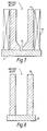
- The cross-sectional view of the mold used in this example is shown in Figure 7.
Mold 4 is provided with a narrow opening 6 at the bottom,adjacent cooling plate 5 andheaters 11 along the sides. Thealumina mold 4 has an inner diameter of 60mm.Heaters 11 were carbon heaters which heated the side ofmold 4 to 1000°C. After casting, the magnetostrictive ingot was cooled at therate 5°C/min. - The magnetostrictive ingot was machined to a 8mm cube and its axial magnetostrictive characteristic was evaluated at room temperature using a strain gauge. The magnetic field was produced by a dipole magnet and the magnetostriction (λ) in the 2 kOe magnetic field was measured. The result was 950 ppm.
- Casting the melted alloy of the same composition as in example 50 with a mold without the cooling end provided, an alloy ingot was obtained. The cross-sectional view of the mold used in this example is shown in Figure 8.
Mold 12 has coolingplate 13 at its bottom. Further, the side of the mold was not heated but all other conditions were the same as example 50. The magnetostriction of the alloy was measured, and a value of 450 ppm was obtained. - As shown in Table 6, the alloys of example 64 to 75 were obtained and measured as similar method as example 63. the heating temperature, cooling after casting and measured values (λ) in same condition (2 kOe) of example 50 are also shown in Table 6. In these examples the mold was heated by 3 split carbon heaters similar to that shown in Figure 7.

- A melted alloy of Tb0.4 Dy0.6 (Fe0.9 Mn0.1)1.93 was obtained by high frequency induction dissolution in an argon atmosphere using a BN crucible. The melted alloy was cast in a 30mm diameter mold heated to 1100°C by a carbon heater, and cooled in a furnace. The ingot of example 76 was obtained. A water cooled copper plate was provided to start the crystal growth.
- The alloy ingot was processed according to the hot extrusion method at a temperature 1050°C and extruding
pressure 4 ton/cm². A magnetostrictive alloy rod 8mm in diameter was obtained. The hot extrusion apparatus is shown in Fig. 9. Theingot 21 was pressed and formed into arod 22 at the noted temperature provided byheaters 23 and formed into the rod by dies 24. - The magnetostrictive alloy rod was machined to a 6mm cube and its magnetostrictive characteristic in the extruded direction and the right angle direction were evaluated at room temperature using a strain gauge. the magnetic field was produced with a dipole magnet and magnetostriction (λ) in the 2kOe magnetic field was measured. The results of a value of 1000 ppm in the extruding direction and a value of 400 ppm in the right angle direction were measured. An anisotropic alloy rod was obtained according to the invention.
- A magnetostrictive alloy rod having the same composition produced according to a grinding process without performing the hot extrusion process was also evaluated. The magnetostrictive characteristic of this rod was a value of 800 ppm in the extrusion direction and 700 ppm in the right angle direction, and the anisotropy was small.
- Furthermore, the magnetostrictive characteristics of the magnetostriction alloy rods produced by varying the composition and processing conditions according to the invention are shown in Table 7.

- A melted alloy of Tb0.5Dy0.5(Fe0.9Mn0.1)1.95 was obtained by high frequency induction dissolution in an argon atmosphere using a BN crucible. A stainless steel pipe, 30 mm in outer diameter and 3mm in thickness, was placed the mold having a 30 mm inner diameter. The mold and pipe were heated to 1100°C by a carbon heater, the melted alloy was poured into the pipe and cooled in the mold. A stainless steel covered alloy ingot was obtained. A water-cooled cooper plate was used as a cooling plate on which to start the crystal growth.
- The stainless steel covered magnetostrictive alloy ingot was processed by the hot extruding at a working temperature 1050°C and extruding
pressure 4 ton/cm² using the equipment shown in Figure 10. A stainless steel covered magnetostrictive alloy rod 8mm in diameter was obtained. As shown in Figure 10, theingot 25 was pressed and formed into arod 27 withheaters 3 providing the elevated temperature and dies 4 creating the forming pressure. - This stainless steel covered super magnetostrictive alloy rod was processed to a 6 mm cube and the magnetostrictive characteristic in the extruding (axial) direction and the right angle direction was evaluated at a room temperature using a strain gauge. The magnetic field was produced with a dipole magnet and the magnetostriction (λ) in the 2kOe magnetic field was measured. The magnetostrictive characteristic obtained was 980 ppm in the extruding axial direction and 390 ppm in the right angle direction.
- Further, a compression fatigue test was conducted on the rod shaped 8mm in diameter and 15 mm in length. After applying stress of 5 kg/cm² repetitively 10⁷ cycles, no cracks or breaks were detected in the sample.
- The present invention has been described with respect to specific embodiments. The present invention is, however, not limited thereto. The scope of the invention is to be determined by the appended claims and their equivalents.
Claims (15)
- A magnetostrictive alloy comprised of a composition whose atomic ratio is expressed by:
TbxRyDy1-x-yFe1-zMnz)w
where x+y is less than 1,
0.005 ≦ y ≦ 0 9,
0.005 ≦ z ≦ 0.5,
1.5 ≦ w ≦ 2.5 and
R is at least one of the following elements Y, Ln, Ce, Pr, Nd and Sm. - A magnetostrictive alloy comprised of a composition containing at least one rare earth element (Re) as specified herein and whose atomic ratio is expressed by:
Re Fep (1.5 ≦ p ≦ 2.5)
where the rare earth element (Re) comprises one or more of the following elements: Y, La, Ce, Pr, Nd, Pm, Sm, Eu, Gd, Tb, Dy, Ho, Er, Tm, Yb and Lu, said alloy being a Laves-type intermetallic compound, and having been grown in the 〈110〉 direction. - Alloy as claimed in claim 1 or 2, which exhibits a value of magnetostriction in excess of 500ppm, in magnetic fields of 2 kOe.
- Alloy as claimed in any preceding claim, which is comprised of the Laves phase.
- Alloy as claimed in any preceding claim, wherein 0.05 ≦ x ≦ 0.5.
- Alloy as claimed in claim 1, being oriented preferentially in one of the specific crystallographic directions 〈110〉 or 〈111〉 of the cubic system.
- Alloy as claimed in claim 6, which consists essentially of crystalline material having the 〈110〉 easy magnetizing axis, said material being grown in the 〈110〉 direction.
- A magnetostrictive alloy having a composition whose atomic ratio is expressed by:
Re (Fe1-q-rMnqMr)₅,
where Re is at least one of the following elements: Y, La, Ce, Pr, Nd, Pm, Sm, Eu, Gd, Tb, Dy, Ho, Er, Tm, Yb and Lu,
M is at least one of the following elements: C, Mg, Al, Si, Ca, Zr, Y, Ga and B,
0.005 ≦ q ≦ 0.5,
0.005≦ r ≦ 0.2,
1.90 ≦ s ≦ 2.10, and
said alloy including an amount of 1-3 phase of 5 vol % or less. - Alloy as claimed in any preceding claim, wherein said Fe in the formula includes an amount of metal T in accordance with the formula:
Fe1-aTa,
where T is at least one of Co and Ni and a is less than 0.5. - Alloy as claimed in claim 1 or as claimed in any of claims 3 to 7, or 9 when dependant upon claim 1, wherein part of the Mn is substituted by element(s) M', in which M' is at least one of the following elements: Mg, Al, Ga, Ru, Rh, Pd, Ag, Cd, In, Sn, Sb, Os, Ir, Pt, Au, Hg, Tl and Pb.
- A method of forming a magnetostrictive alloy including the steps of:a) casting said alloy in a heated mould, andb) providing a temperature gradient in said mould, andc) solidifying said alloy in said mould to form a solidified alloy.
- A method as claimed in claim 11 including the step of:
plastically deforming said solidified alloy by hot working. - A method as claimed in claim 12 including the step of covering said solidified alloy prior to hot working.
- A method of forming a magnetostrictive alloy as claimed in any one of claims 1 and 3 to 7 when dependant upon claim 1, or as claimed in claim 8, or 9 when dependant upon claim 8,
said method including the steps of:a) casting said alloy in a heated mould, andb) providing a temperature gradient in said mould, andc) solidifying said alloy in said mould to form a solidified alloy. - A method of forming a magnetostrictive alloy as claimed in any one of claims 2 or 3 to 7, or 9 when dependant upon claim 2, comprising:a) casting said alloy in a heated mould, andb) providing a temperature gradient in said mould,c) solidifying said alloy in said mould to form a solidified Laves-type intermetallic compound, andd) growing said alloy in the 〈110〉 direction.
Applications Claiming Priority (6)
| Application Number | Priority Date | Filing Date | Title |
|---|---|---|---|
| JP35522/91 | 1991-02-05 | ||
| JP3552291 | 1991-02-05 | ||
| JP3062333A JPH04297545A (en) | 1991-03-27 | 1991-03-27 | Production of ultra-magnetostrictive material |
| JP62333/91 | 1991-03-27 | ||
| JP26566391A JPH05146805A (en) | 1991-10-15 | 1991-10-15 | Manufacture of ultra magnetostorictive alloy |
| JP265663/91 | 1991-10-15 |
Publications (2)
| Publication Number | Publication Date |
|---|---|
| EP0509628A1 true EP0509628A1 (en) | 1992-10-21 |
| EP0509628B1 EP0509628B1 (en) | 1999-06-02 |
Family
ID=27288789
Family Applications (1)
| Application Number | Title | Priority Date | Filing Date |
|---|---|---|---|
| EP92300980A Expired - Lifetime EP0509628B1 (en) | 1991-02-05 | 1992-02-05 | Magnetostrictive alloys and method of manufacturing thereof |
Country Status (3)
| Country | Link |
|---|---|
| US (2) | US5336337A (en) |
| EP (1) | EP0509628B1 (en) |
| DE (1) | DE69229299D1 (en) |
Cited By (3)
| Publication number | Priority date | Publication date | Assignee | Title |
|---|---|---|---|---|
| WO1997023913A1 (en) * | 1995-12-21 | 1997-07-03 | The University Of Hull | Magnetic materials |
| CN107085656A (en) * | 2017-04-10 | 2017-08-22 | 西华大学 | A kind of method for predicting iron gallium rare earth alloy Magnetostriction |
| CN110423932A (en) * | 2019-08-23 | 2019-11-08 | 南京信息职业技术学院 | A kind of magnetostriction materials and preparation method of light rare earth Pr doping |
Families Citing this family (13)
| Publication number | Priority date | Publication date | Assignee | Title |
|---|---|---|---|---|
| US5739600A (en) * | 1995-03-24 | 1998-04-14 | Kabushiki Kaisha Toshiba | Underwater magnetrostrictive vibration device |
| US6273965B1 (en) * | 1996-10-18 | 2001-08-14 | Iowa State University Research Foundation, Inc. | Magnetostrictive materials and method for improving AC characteristics in same |
| JPH11189854A (en) * | 1997-10-23 | 1999-07-13 | Alps Electric Co Ltd | Magnetostrictive material |
| DE60220773T2 (en) * | 2001-02-07 | 2008-03-06 | Tdk Corp. | PROCESS FOR PRODUCING A SINTER PRODUCT |
| JP4076075B2 (en) * | 2002-05-16 | 2008-04-16 | Tdk株式会社 | Heat treatment method for giant magnetostrictive material |
| US7160636B2 (en) * | 2002-09-13 | 2007-01-09 | Nec Tokin Corporation | Ferrite thin film, method of manufacturing the same and electromagnetic noise suppressor using the same |
| US7179338B2 (en) * | 2002-09-27 | 2007-02-20 | University Of Utah Research Foundation | Control of engineering processes using magnetostrictive alloy compositions |
| CN100352961C (en) * | 2005-04-21 | 2007-12-05 | 南京大学 | Pr series rare earth super magnetostric tive material and its preparing method |
| US7481918B2 (en) * | 2005-04-22 | 2009-01-27 | Siemens Water Technologies Holding Corp. | Vibratory mixer |
| EP2077567B1 (en) * | 2007-05-02 | 2012-08-08 | Hitachi Metals, Ltd. | R-t-b sintered magnet |
| EP2058634A1 (en) * | 2007-11-06 | 2009-05-13 | FAFNIR GmbH | Application of an iron/cobalt alloy for magnetostrictive position sensoring |
| US8053867B2 (en) * | 2008-08-20 | 2011-11-08 | Honeywell International Inc. | Phosphorous-comprising dopants and methods for forming phosphorous-doped regions in semiconductor substrates using phosphorous-comprising dopants |
| KR101180949B1 (en) * | 2010-07-09 | 2012-09-07 | 기아자동차주식회사 | Catalyst for diesel particulate filter, preparation method of the same, and smoke reduction device of diesel engine |
Citations (3)
| Publication number | Priority date | Publication date | Assignee | Title |
|---|---|---|---|---|
| EP0361969A2 (en) * | 1988-09-29 | 1990-04-04 | Kabushiki Kaisha Toshiba | Super-magnetostrictive alloy |
| EP0405362A1 (en) * | 1989-06-30 | 1991-01-02 | Nkk Corporation | Method for manufacturing alloy rod having giant magnetostriction |
| EP0419098A1 (en) * | 1989-09-08 | 1991-03-27 | Kabushiki Kaisha Toshiba | Cobalt-iron magnetostrictive alloys, and their use in products |
Family Cites Families (6)
| Publication number | Priority date | Publication date | Assignee | Title |
|---|---|---|---|---|
| US4378258A (en) * | 1972-03-16 | 1983-03-29 | The United States Of America As Represented By The Secretary Of The Navy | Conversion between magnetic energy and mechanical energy |
| US4375372A (en) * | 1972-03-16 | 1983-03-01 | The United States Of America As Represented By The Secretary Of The Navy | Use of cubic rare earth-iron laves phase intermetallic compounds as magnetostrictive transducer materials |
| JPS609855A (en) * | 1983-06-28 | 1985-01-18 | Toshiba Corp | Magnetic alloy |
| JPS6133892A (en) * | 1984-07-26 | 1986-02-17 | 株式会社東芝 | Method of measuring driving torque of joint of robot |
| US4609402A (en) * | 1985-10-28 | 1986-09-02 | Iowa State University Research Foundation, Inc. | Method of forming magnetostrictive rods from rare earth-iron alloys |
| US4770704A (en) * | 1987-03-13 | 1988-09-13 | Iowa State University Research Foundation, Inc. | Continuous method for manufacturing grain-oriented magnetostrictive bodies |
-
1992
- 1992-02-04 US US07/830,569 patent/US5336337A/en not_active Expired - Lifetime
- 1992-02-05 EP EP92300980A patent/EP0509628B1/en not_active Expired - Lifetime
- 1992-02-05 DE DE69229299T patent/DE69229299D1/en not_active Expired - Lifetime
-
1993
- 1993-10-22 US US08/140,308 patent/US5527398A/en not_active Expired - Lifetime
Patent Citations (3)
| Publication number | Priority date | Publication date | Assignee | Title |
|---|---|---|---|---|
| EP0361969A2 (en) * | 1988-09-29 | 1990-04-04 | Kabushiki Kaisha Toshiba | Super-magnetostrictive alloy |
| EP0405362A1 (en) * | 1989-06-30 | 1991-01-02 | Nkk Corporation | Method for manufacturing alloy rod having giant magnetostriction |
| EP0419098A1 (en) * | 1989-09-08 | 1991-03-27 | Kabushiki Kaisha Toshiba | Cobalt-iron magnetostrictive alloys, and their use in products |
Cited By (5)
| Publication number | Priority date | Publication date | Assignee | Title |
|---|---|---|---|---|
| WO1997023913A1 (en) * | 1995-12-21 | 1997-07-03 | The University Of Hull | Magnetic materials |
| GB2308384B (en) * | 1995-12-21 | 1999-09-15 | Univ Hull | Magnetic materials |
| US5997660A (en) * | 1995-12-21 | 1999-12-07 | University Of Hull | Magnetic materials |
| CN107085656A (en) * | 2017-04-10 | 2017-08-22 | 西华大学 | A kind of method for predicting iron gallium rare earth alloy Magnetostriction |
| CN110423932A (en) * | 2019-08-23 | 2019-11-08 | 南京信息职业技术学院 | A kind of magnetostriction materials and preparation method of light rare earth Pr doping |
Also Published As
| Publication number | Publication date |
|---|---|
| US5527398A (en) | 1996-06-18 |
| DE69229299D1 (en) | 1999-07-08 |
| US5336337A (en) | 1994-08-09 |
| EP0509628B1 (en) | 1999-06-02 |
Similar Documents
| Publication | Publication Date | Title |
|---|---|---|
| US5336337A (en) | Magnetrostrictive materials and methods of making such materials | |
| JP4288687B2 (en) | Amorphous alloy composition | |
| US5110374A (en) | Rare earth-iron-boron magnet powder and process of producing same | |
| US7670443B2 (en) | Magnetic alloy material and method of making the magnetic alloy material | |
| DE69822798T2 (en) | MANUFACTURING METHOD FOR A THIN MAGNETIC DISC WITH A MICROCRYSTALLINE STRUCTURE | |
| CA2559121A1 (en) | Bulk solidified quenched material and process for producing the same | |
| JPH03153006A (en) | Permanent magnet and raw material therefor | |
| JP3771710B2 (en) | Raw material alloy for rare earth magnet and method for producing the same | |
| JP4238999B2 (en) | Manufacturing method of rare earth sintered magnet | |
| JP6760538B2 (en) | Rare earth magnet powder manufacturing method | |
| JPH02250922A (en) | Production of rare earth element-transition element -b magnet | |
| JP3367069B2 (en) | Manufacturing method of giant magnetostrictive alloy rod | |
| JPH01246342A (en) | Supermagnetostrictive material and its manufacture | |
| JPH02250920A (en) | Production of rare earth element-transition element -b magnet by forging | |
| JP4817138B2 (en) | Giant magnetostrictive material flakes, method for producing the same, and giant magnetostrictive sintered body | |
| EP1270756B1 (en) | Supermagnetostrictive alloy and method for preparation thereof | |
| JPH09246026A (en) | Permanent magnet and its manufacture | |
| JPH0584043B2 (en) | ||
| JPH048923B2 (en) | ||
| JPH02101710A (en) | Permanent magnet and manufacture thereof | |
| JP3200137B2 (en) | Giant magnetostrictive alloy | |
| EP0522177B1 (en) | Anisotropic Rare Earth Magnet | |
| JPS63226007A (en) | Rare-earth magnet and manufacture thereof | |
| JPH0732091B2 (en) | Manufacturing method of rare earth / boron / iron permanent magnet | |
| CN113046619A (en) | Large-expansion-amount rare earth giant magnetostrictive material and preparation method thereof |
Legal Events
| Date | Code | Title | Description |
|---|---|---|---|
| PUAI | Public reference made under article 153(3) epc to a published international application that has entered the european phase |
Free format text: ORIGINAL CODE: 0009012 |
|
| 17P | Request for examination filed |
Effective date: 19920302 |
|
| AK | Designated contracting states |
Kind code of ref document: A1 Designated state(s): DE GB |
|
| 17Q | First examination report despatched |
Effective date: 19950822 |
|
| GRAG | Despatch of communication of intention to grant |
Free format text: ORIGINAL CODE: EPIDOS AGRA |
|
| GRAG | Despatch of communication of intention to grant |
Free format text: ORIGINAL CODE: EPIDOS AGRA |
|
| GRAH | Despatch of communication of intention to grant a patent |
Free format text: ORIGINAL CODE: EPIDOS IGRA |
|
| GRAH | Despatch of communication of intention to grant a patent |
Free format text: ORIGINAL CODE: EPIDOS IGRA |
|
| GRAA | (expected) grant |
Free format text: ORIGINAL CODE: 0009210 |
|
| AK | Designated contracting states |
Kind code of ref document: B1 Designated state(s): DE GB |
|
| REF | Corresponds to: |
Ref document number: 69229299 Country of ref document: DE Date of ref document: 19990708 |
|
| PG25 | Lapsed in a contracting state [announced via postgrant information from national office to epo] |
Ref country code: DE Free format text: LAPSE BECAUSE OF FAILURE TO SUBMIT A TRANSLATION OF THE DESCRIPTION OR TO PAY THE FEE WITHIN THE PRESCRIBED TIME-LIMIT Effective date: 19990903 |
|
| PLBE | No opposition filed within time limit |
Free format text: ORIGINAL CODE: 0009261 |
|
| STAA | Information on the status of an ep patent application or granted ep patent |
Free format text: STATUS: NO OPPOSITION FILED WITHIN TIME LIMIT |
|
| 26N | No opposition filed | ||
| REG | Reference to a national code |
Ref country code: GB Ref legal event code: IF02 |
|
| PGFP | Annual fee paid to national office [announced via postgrant information from national office to epo] |
Ref country code: GB Payment date: 20110209 Year of fee payment: 20 |
|
| REG | Reference to a national code |
Ref country code: GB Ref legal event code: PE20 Expiry date: 20120204 |
|
| PG25 | Lapsed in a contracting state [announced via postgrant information from national office to epo] |
Ref country code: GB Free format text: LAPSE BECAUSE OF EXPIRATION OF PROTECTION Effective date: 20120204 |