EP0509010B1 - Verfahren und vorrichtung zum abziehen und absperren einer schmelze insbesondere aus kunststoff - Google Patents
Verfahren und vorrichtung zum abziehen und absperren einer schmelze insbesondere aus kunststoff Download PDFInfo
- Publication number
- EP0509010B1 EP0509010B1 EP91901773A EP91901773A EP0509010B1 EP 0509010 B1 EP0509010 B1 EP 0509010B1 EP 91901773 A EP91901773 A EP 91901773A EP 91901773 A EP91901773 A EP 91901773A EP 0509010 B1 EP0509010 B1 EP 0509010B1
- Authority
- EP
- European Patent Office
- Prior art keywords
- melt
- nozzle plate
- cover
- temperature
- melter
- Prior art date
- Legal status (The legal status is an assumption and is not a legal conclusion. Google has not performed a legal analysis and makes no representation as to the accuracy of the status listed.)
- Expired - Lifetime
Links
- 239000000155 melt Substances 0.000 title claims abstract description 45
- 238000000034 method Methods 0.000 title claims abstract description 12
- 239000000463 material Substances 0.000 title claims abstract description 5
- 230000000903 blocking effect Effects 0.000 title claims abstract 14
- 239000000289 melt material Substances 0.000 claims abstract description 17
- 238000007711 solidification Methods 0.000 claims abstract description 8
- 230000008023 solidification Effects 0.000 claims abstract description 8
- 230000001105 regulatory effect Effects 0.000 claims abstract description 3
- 238000010438 heat treatment Methods 0.000 claims description 9
- 238000001816 cooling Methods 0.000 claims description 8
- 238000007789 sealing Methods 0.000 description 7
- 238000009413 insulation Methods 0.000 description 6
- 239000002826 coolant Substances 0.000 description 4
- 230000000694 effects Effects 0.000 description 3
- 238000002844 melting Methods 0.000 description 2
- 230000008018 melting Effects 0.000 description 2
- QVGXLLKOCUKJST-UHFFFAOYSA-N atomic oxygen Chemical compound [O] QVGXLLKOCUKJST-UHFFFAOYSA-N 0.000 description 1
- 238000005266 casting Methods 0.000 description 1
- 238000010276 construction Methods 0.000 description 1
- 239000007788 liquid Substances 0.000 description 1
- 230000003647 oxidation Effects 0.000 description 1
- 238000007254 oxidation reaction Methods 0.000 description 1
- 229910052760 oxygen Inorganic materials 0.000 description 1
- 239000001301 oxygen Substances 0.000 description 1
- 230000035515 penetration Effects 0.000 description 1
- 239000000126 substance Substances 0.000 description 1
Images
Classifications
-
- D—TEXTILES; PAPER
- D01—NATURAL OR MAN-MADE THREADS OR FIBRES; SPINNING
- D01D—MECHANICAL METHODS OR APPARATUS IN THE MANUFACTURE OF ARTIFICIAL FILAMENTS, THREADS, FIBRES, BRISTLES OR RIBBONS
- D01D4/00—Spinnerette packs; Cleaning thereof
-
- B—PERFORMING OPERATIONS; TRANSPORTING
- B29—WORKING OF PLASTICS; WORKING OF SUBSTANCES IN A PLASTIC STATE IN GENERAL
- B29C—SHAPING OR JOINING OF PLASTICS; SHAPING OF MATERIAL IN A PLASTIC STATE, NOT OTHERWISE PROVIDED FOR; AFTER-TREATMENT OF THE SHAPED PRODUCTS, e.g. REPAIRING
- B29C48/00—Extrusion moulding, i.e. expressing the moulding material through a die or nozzle which imparts the desired form; Apparatus therefor
- B29C48/25—Component parts, details or accessories; Auxiliary operations
- B29C48/78—Thermal treatment of the extrusion moulding material or of preformed parts or layers, e.g. by heating or cooling
- B29C48/86—Thermal treatment of the extrusion moulding material or of preformed parts or layers, e.g. by heating or cooling at the nozzle zone
- B29C48/87—Cooling
-
- B—PERFORMING OPERATIONS; TRANSPORTING
- B29—WORKING OF PLASTICS; WORKING OF SUBSTANCES IN A PLASTIC STATE IN GENERAL
- B29C—SHAPING OR JOINING OF PLASTICS; SHAPING OF MATERIAL IN A PLASTIC STATE, NOT OTHERWISE PROVIDED FOR; AFTER-TREATMENT OF THE SHAPED PRODUCTS, e.g. REPAIRING
- B29C48/00—Extrusion moulding, i.e. expressing the moulding material through a die or nozzle which imparts the desired form; Apparatus therefor
- B29C48/03—Extrusion moulding, i.e. expressing the moulding material through a die or nozzle which imparts the desired form; Apparatus therefor characterised by the shape of the extruded material at extrusion
- B29C48/05—Filamentary, e.g. strands
-
- B—PERFORMING OPERATIONS; TRANSPORTING
- B29—WORKING OF PLASTICS; WORKING OF SUBSTANCES IN A PLASTIC STATE IN GENERAL
- B29C—SHAPING OR JOINING OF PLASTICS; SHAPING OF MATERIAL IN A PLASTIC STATE, NOT OTHERWISE PROVIDED FOR; AFTER-TREATMENT OF THE SHAPED PRODUCTS, e.g. REPAIRING
- B29C48/00—Extrusion moulding, i.e. expressing the moulding material through a die or nozzle which imparts the desired form; Apparatus therefor
- B29C48/25—Component parts, details or accessories; Auxiliary operations
- B29C48/30—Extrusion nozzles or dies
- B29C48/345—Extrusion nozzles comprising two or more adjacently arranged ports, for simultaneously extruding multiple strands, e.g. for pelletising
-
- B—PERFORMING OPERATIONS; TRANSPORTING
- B29—WORKING OF PLASTICS; WORKING OF SUBSTANCES IN A PLASTIC STATE IN GENERAL
- B29C—SHAPING OR JOINING OF PLASTICS; SHAPING OF MATERIAL IN A PLASTIC STATE, NOT OTHERWISE PROVIDED FOR; AFTER-TREATMENT OF THE SHAPED PRODUCTS, e.g. REPAIRING
- B29C48/00—Extrusion moulding, i.e. expressing the moulding material through a die or nozzle which imparts the desired form; Apparatus therefor
- B29C48/25—Component parts, details or accessories; Auxiliary operations
- B29C48/78—Thermal treatment of the extrusion moulding material or of preformed parts or layers, e.g. by heating or cooling
- B29C48/86—Thermal treatment of the extrusion moulding material or of preformed parts or layers, e.g. by heating or cooling at the nozzle zone
-
- B—PERFORMING OPERATIONS; TRANSPORTING
- B29—WORKING OF PLASTICS; WORKING OF SUBSTANCES IN A PLASTIC STATE IN GENERAL
- B29C—SHAPING OR JOINING OF PLASTICS; SHAPING OF MATERIAL IN A PLASTIC STATE, NOT OTHERWISE PROVIDED FOR; AFTER-TREATMENT OF THE SHAPED PRODUCTS, e.g. REPAIRING
- B29C48/00—Extrusion moulding, i.e. expressing the moulding material through a die or nozzle which imparts the desired form; Apparatus therefor
- B29C48/25—Component parts, details or accessories; Auxiliary operations
- B29C48/78—Thermal treatment of the extrusion moulding material or of preformed parts or layers, e.g. by heating or cooling
- B29C48/86—Thermal treatment of the extrusion moulding material or of preformed parts or layers, e.g. by heating or cooling at the nozzle zone
- B29C48/865—Heating
-
- B—PERFORMING OPERATIONS; TRANSPORTING
- B29—WORKING OF PLASTICS; WORKING OF SUBSTANCES IN A PLASTIC STATE IN GENERAL
- B29C—SHAPING OR JOINING OF PLASTICS; SHAPING OF MATERIAL IN A PLASTIC STATE, NOT OTHERWISE PROVIDED FOR; AFTER-TREATMENT OF THE SHAPED PRODUCTS, e.g. REPAIRING
- B29C48/00—Extrusion moulding, i.e. expressing the moulding material through a die or nozzle which imparts the desired form; Apparatus therefor
- B29C48/03—Extrusion moulding, i.e. expressing the moulding material through a die or nozzle which imparts the desired form; Apparatus therefor characterised by the shape of the extruded material at extrusion
Definitions
- the invention relates to a method and a device for withdrawing and shutting off a melt, in particular made of plastic, with a heatable pourer which acts as a melt distributor and is provided with a shut-off valve and from which the melt flows into a nozzle plate, and the melt by means of nozzles in a plurality of one each Dividing the strand, the temperature of the pourer and the nozzle plate being regulated separately, the shut-off valve being closed to shut off the melt, and the nozzle plate being sealed off with a lid.
- a generic method and a generic device are known from DE-A-2 820 329.
- the sealing of the melt at the nozzle orifices in the event of the melt flow being shut off is therefore necessary in order to prevent the penetration of air from the nozzle orifices, which can trigger an oxidation process of the melt which leads to an undesirable chemical change in the melt material.
- the lid used for this locking has previously been screwed onto the nozzle plate. It is necessary that the cover rests on the nozzle plate with considerable pressure in order to achieve the required sealing effect. It has been found that a warping of the lid is evidently inevitable due to the existing temperature differences, which means that the sealing of the nozzle orifices against the entry of air takes place only incompletely.
- the invention has for its object to improve the sealing of the nozzle orifices in the event that the melt flow is shut off. According to the invention, this is done by keeping the temperature of the pourer and the nozzle plate substantially at the same level for removing the melt when the shut-off valve is open, in order to shut off the melt
- the nozzle plate is brought to a temperature just above the solidification temperature of the melt material, and that when the shut-off valve is closed, the lid, which is cooled to a temperature significantly below the solidification temperature, is placed on the nozzle plate, into which a remainder of the melt flows and seals the nozzle orifices in the solidified state.
- the temperature level in the pourer and in the nozzle plate which is kept the same during the removal of the melt, is changed when the melt flow is shut off, so that, while the temperature in the pourer is kept unchanged, the temperature level in the nozzle plate is lowered, to the extent that a just above in the nozzle plate the solidification temperature of the melt material prevails. If the melting material-receiving cover then converts the melting material into the solidified state due to its considerable cooling, the solidified material can seal the nozzle orifices, and also permanently, because from there the lowering of the temperature in the nozzle plate keeps the one held by the lid solidified melt material cannot be melted again.
- the solidified melt material thus results in a reliable closure of the nozzle orifices, whereby the entry of air and thus oxygen into the area of the melt is reliably avoided.
- This type of sealing of the nozzle plate also makes it possible, as it were, to apply the lid only to the nozzle plate, without the need for special pressure, since the required sealing is not effected by the lid itself, but, as I said, by the solidified melt material.
- the device for carrying out the method described above is based on a heatable pourer which acts as a melt distributor and is provided with a shut-off valve and to which a melt is connected by means of nozzles to a plurality of nozzle plates which each divide into one strand and which can be sealed with a lid.
- This device is advantageously designed in such a way that the nozzle plate and the lid are each provided with a separate and individually controllable heating or cooling system, a casting and nozzle plate sealingly connecting the pourer and the nozzle plate Temperature insulation layer is used, and that the lid has a recess extending over the nozzle mouths as a collecting container for melt cooled by the lid.
- the recess in the lid which serves as a collecting container for the melt cooled from the lid, can be made relatively flat, so that a relatively thin layer of solidified melt material forms in the recess. This is quite sufficient for the sealing effect.
- the temperature insulation layer provided between the caster and the nozzle plate ensures that the temperature prevailing in the caster can practically have no effect on the temperature in the nozzle plate which has cooled in comparison.
- the cover is removed from the nozzle plate.
- the lid can take the solidified melt layer with it in its recess.
- the cover can be provided in the region of its recess with a plunger passing through the cover for ejecting solidified melt material. When the cover is removed, the plunger is pushed forward, causing the solidified melt layer to fall out of the recess in the cover.
- the lid can be attached or removed by hand, but it is also possible to do this process e.g. B. by a pivoting or sliding mechanism. It is particularly advantageous that the cover poses no danger to the operating personnel because of its cooling.
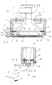
- FIG. 1 shows a device for withdrawing and shutting off a melt, in particular made of plastic, with the pourer 1, to which a plastic melt is fed via the feed line 2.
- the shut-off valve 3 is placed in the feed line 2.
- the caster 1 is surrounded by a heating chamber 4 which surrounds it in the manner of a ring, into which a heating liquid flows via the inlet 5 and flows out of the latter via the outlet 6.
- the temperature of the caster is continuously measured by means of the temperature sensor 7.
- the caster 1 is surrounded by the cross-hatched insulating jacket 8.
- the caster has the interior 9 filled with the melt, which widens accordingly in the direction of the subsequent nozzle plate 10.
- the temperature insulation layer 12 adjoins the flat end face 11 of the caster 1, which sealingly connects the end face 11 of the caster to the relevant side of the nozzle plate 10.
- the temperature insulation layer serves to prevent direct heat transfer from the caster 1 to the nozzle plate 10.
- the temperature insulation layer 12 is followed by the nozzle plate 10 which is penetrated by channels 13 which end in the nozzles 14. If the melt is drawn off, it flows through the interior 9 of the caster 1 through the channels 13 and emerges from the nozzles 14 on the underside of the nozzle plate 10.
- the nozzle plate 10 is connected via the inlet 15 and the outlet 16 to a heating or coolant flow for which channels running in the nozzle plate 10 are provided.
- the nozzle plate 10 is kept at the desired temperature level by means of the medium flowing through the channels 17.
- the representation in FIG. 1 is therefore the operating phase in which the flow of the melt is shut off.
- the cover 18 has the channel 20 which extends over its entire length and is connected to a flow of coolant via the inlet 21 into the outlet 22. With the help of this coolant, the cover 18 can be brought to a temperature substantially below the temperature of the nozzle plate 10.
- the cover 18 has been placed on the nozzle plate 10 together with the closure of the shut-off valve 3, so that only a remnant of melt can get into the recess 19 from the interior 9 of the caster 1.
- This melt residue solidifies due to the considerable cooling of the cover 18 with respect to the nozzle plate 10, so that a cake of solidified melt forms which essentially fills the space of the recess 19 and thus closes the nozzle orifices 23 securely and airtight. So that the cover 18 does not receive too much heat from the nozzle plate 10, it has been brought to a temperature just above the solidification temperature of the melt material.
- the melt material remaining within the channels 13 and the nozzles 14 cannot thus freeze, which would considerably delay a later process of removing the melt, since for this purpose the channels 13 and the nozzles 14 would first have to be cleaned of solidified melt material.
- the temperature level in caster 1 remains practically unchanged compared to the process of removing the melt.
- FIG. 2 shows a design of a caster modified compared to FIG. 1, namely a device with two rows of nozzles 14.
- the caster 24 is elongated here and is protected against temperature loss by the insulation jacket 25.
- the nozzle plate 26 is screwed here to the wall of the caster 24 by means of the screws 27. For the sake of simplifying the illustration, only one screw 27 is shown.
- the temperature of the nozzle plate 26 is measured by the temperature sensor 28.
- the nozzle plate 26 is provided with the channels 29 and the cover 30 with the channels 31, which ensure a corresponding temperature setting of the nozzle plate 26 and cover 30 in the manner described above.
- the heating of the caster 24 is omitted here for the sake of simplifying the illustration.
- the cover 30 has the recess embedded below the nozzles 14, which in the exemplary embodiment according to FIG. 1 serves to hold a remainder of the melt material when the melt flow is shut off, the melt cake solidifying in the recess 32 then reliably seals the nozzles 14.
- the figure shows how the cover 30 is brought up to the nozzle plate 26. This is done here by means of the joint 33, in which the arm 34 is mounted, to which the nozzle plate 30 is attached.
- the plunger 35 is inserted into the cover 30 and serves to push a cake, which is seated in the recess 32, out of solidified melt material. This is shown in FIG. 2 in the area of the dash-dotted representation of the cover 30, which shows the position of the cover 30 pivoted away from the nozzle plate 26.
- the plunger 35 is drawn here in an advanced position, brought about by the pin 36.
- the plunger 35 ejects the melt cake 37.
- some other heating medium e.g. B. an electric heater can be replaced.
- the heating would then have to be switched off completely, which may include basic cooling with a cooling medium.
Landscapes
- Engineering & Computer Science (AREA)
- Mechanical Engineering (AREA)
- Physics & Mathematics (AREA)
- Thermal Sciences (AREA)
- Manufacturing & Machinery (AREA)
- Textile Engineering (AREA)
- Coating Apparatus (AREA)
- Injection Moulding Of Plastics Or The Like (AREA)
- Processing And Handling Of Plastics And Other Materials For Molding In General (AREA)
- Extrusion Moulding Of Plastics Or The Like (AREA)
- Spinning Methods And Devices For Manufacturing Artificial Fibers (AREA)
- Gasification And Melting Of Waste (AREA)
- Processing Of Solid Wastes (AREA)
- Medicines That Contain Protein Lipid Enzymes And Other Medicines (AREA)
Abstract
Description
- Die Erfindung bezieht sich auf ein Verfahren und eine Vorrichtung zum Abziehen und Absperren einer Schmelze insbesondere aus Kunststoff mit einem als Schmelzeverteiler wirkenden mit einem Absperrventil versehenen beheizbaren Gießer, aus dem die Schmelze in eine Düsenplatte fließt, die Schmelze mittels Düsen in eine Mehrzahl von je einem Strang aufteilt, wobei die Temperatur von Gießer und Düsenplatte getrennt geregelt und zum Absperren der Schmelze das Absperrventil geschlossen und die Düsenplatte mit einem Deckel dicht abgeschlossen wird.
- Ein gattungsgemäßes Verfahren und eine gattungsgemäße Vorrichtung sind aus der DE-A-2 820 329 bekannt.
- Das Abschließen der Schmelze an den Düsenmündungen im Falle des Absperrens des Schmelzeflußes ist darum erforderlich, um von den Düsenmündungen her das Eindringen von Luft zu verhindern, das einen Oxydationsprozeß der Schmelze auslösen kann der zu einer unerwünschten chemischen Veränderung des Schmelzematerials führt. Der für dieses Abschließen verwendete Deckel wurde bisher üblicherweise an die Düsenplatte angeschraubt. Es ist dabei erforderlich, daß der Deckel mit erheblichem Druck an der Düsenplatte anliegt, um die erforderliche Dichtwirkung zu erzielen. Es hat sich dabei herausgestellt, daß offenbar aufgrund vorhandener Temperaturunterschiede ein Verziehen des Deckels unvermeidlich ist, was dazu führt, daß die Abdichtung der Düsenmündungen gegenüber dem Zutritt von Luft nur unvollständig erfolgt.
- Der Erfindung liegt die Aufgabe zugrunde, die Abdichtung der Düsenmündungen im Falle des Absperrens des Schmelzeflußes zu verbessern. Erfindungsgemäß geschieht dies dadurch, daß zum Abziehen der Schmelze bei geöffnetem Absperrventil die Temperatur des Gießers und der Düsenplatte im wesentlichen auf gleichem Niveau gehalten wird, zum Absperren der Schmelze bei geschlossenem Absperrventil die Düsenplatte auf eine gerade oberhalb der Erstarrungstemperatur des Schmelzematerials liegende Temperatur gebracht wird, und daß mit dem Schließen des Absperrventils der auf eine erheblich unter der Erstarrungstemperatur liegende Temperatur gekühlte Deckel an die Düsenplatte angelegt wird, in die ein Rest der Schmelze fließt und in erstarrtem Zustand die Düsenmündungen dichtend abschließt.
- Das während des Abziehens der Schmelze gleich gehaltene Temperaturniveau im Gießer und in der Düsenplatte wird beim Absperren des Schmelzeflußes so geändert, daß bei unverändert gehaltener Temperatur im Gießer demgegenüber das Temperaturniveau in der Düsenplatte abgesenkt wird, und zwar soweit, daß in der Düsenplatte eine gerade oberhalb der Erstarrungstemperatur des Schmelzematerials liegende Temperatur herrscht. Wenn dann der Schmelzematerial aufnehmende Deckel aufgrund seiner erheblichen Kühlung das Schmelzematerial in den erstarrten Zustand überführt, so kann das erstarrte Material die Düsenmündungen dichtend abschließen, und zwar auch dauerhaft, da wegen der erfolgten Absenkung der Temperatur in der Düsenplatte von dort her das vom Deckel gehaltene erstarrte Schmelzematerial nicht wieder zum Schmelzen gebracht werden kann. Es ergibt sich somit durch das erstarrte Schmelzematerial selbst ein sicherer Abschluß der Düsenmündungen, wodurch das Eintreten von Luft und damit von Sauerstoff in den Bereich der Schmelze mit Sicherheit vermieden wird. Diese Art der Abdichtung der Düsenplatte erlaubt es auch, den Deckel gewissermaßen nur an die Düsenplatte anzulegen, ohne das hierfür ein besonderer Druck erforderlich ist, da die erforderliche Abdichtung nicht vom Deckel selbst, sondern, wie gesagt, von dem erstarrten Schmelzematerial bewirkt wird.
- Die Vorrichtung zur Durchführung des vorstehend beschriebenen Verfahrens beruht auf einem als Schmelzeverteiler wirkenden, mit einem Absperrventil versehenen beheizbaren Gießer, an den eine die Schmelze mittels Düsen auf eine Mehrzahl von je einem Strang aufteilende Düsenplatte angeschlossen ist, die mit einem Deckel dicht abschließbar ist. Vorteilhaft gestaltet man diese Vorrichtung so, daß die Düsenplatte und der Deckel je mit einem getrennten und einzeln regelbaren Heiz- bzw. Kühlsystem versehen ist, wobei zwischen Gießer und Düsenplatte eine Gießer und Düsenplatte dichtend verbindende Temperaturisolationslage eingesetzt ist, und daß der Deckel eine sich über die Düsenmündungen erstreckende Aussparung als Auffangbehälter für vom Deckel abgekühlte Schmelze aufweist.
- Die Aussparung im Deckel, die als Auffangbehälter für die vom Deckel abgekühlte Schmelze dient, kann relativ flach ausgebildet sein, so daß sich eine relativ dünne Schicht von erstarrtem Schmelzematerial in der Aussparung ausbildet. Dies ist für den Effekt der Abdichtung völlig ausreichend. Dabei sorgt die zwischen Gießer und Düsenplatte vorgesehene Temperaturisolationslage dafür, daß die im Gießer herrschende Temperatur sich praktisch nicht auf die Temperatur in der demgegenüber abgekühlten Düsenplatte auswirken kann.
- Wenn aus der Vorrichtung Schmelze wieder abgezogen werden soll, wird der Deckel von der Düsenplatte abgenommen. Je nach dem verwendeten Schmelzematerial kann der Deckel dabei in seiner Aussparung die erstarrte Schmelzeschicht mitnehmen. Für diesen Fall kann man den Deckel im Bereich seiner Aussparung mit einem den Deckel durchsetzenden Stößel zum Ausstoßen von erstarrtem Schmelzematerial versehen. Bei abgenommenem Deckel wird dann der Stößel vorgestoßen, wodurch die erstarrte Schmelzeschicht aus der Aussparung des Deckels herausfällt.
- Den Deckel kann man von Hand anbringen bzw. abnehmen, es ist aber auch möglich, diesen Vorgang z. B. durch einen Schwenk- oder Schiebemechanismus auszuführen. Es ist dabei von besonderem Vorteil, daß der Deckel wegen seiner Kühlung für das Bedienungspersonal keine Gefahr bildet.
- In den Figuren sind Ausführungsbeispiele der Erfindung dargestellt.
Es zeigen - Figur 1 in Prinzipdarstellung einen Schnitt durch einen Gießer mit Düsenplatte und an der Düsenplatte anliegenden Deckel,
- Figur 2 eine abgewandelte Konstruktion mit einem gegenüber der Düsenplatte anschwenkbaren Deckel.
- Figur 1 zeigt eine Vorrichtung zum Abziehen und Absperren einer Schmelze insbesondere aus Kunststoff mit dem Gießer 1, dem über die Zuleitung 2 eine Kunststoffschmelze zugeführt wird. In die Zuleitung 2 ist das Absperrventil 3 gelegt. Der Gießer 1 wird von einem diesen ringartig umgebenden Heizraum 4 umfaßt, in den über den Einlaß 5 eine Heizflüssigkeit einströmt und aus diesem über den Auslaß 6 abströmt. Die Temperatur des Gießers wird mittels des Temperaturfühlers 7 laufend gemessen. Der Gießer 1 ist zwecks Verhinderung eines Wärmeverlustes durch den kreuzschraffiert gezeichneten Isoliermantel 8 umgeben. Der Gießer besitzt den von der Schmelze ausgefüllten Innenraum 9, der sich in Richtung auf die anschließende Düsenplatte 10 entsprechend aufweitet.
- An die ebene Stirnfläche 11 des Gießers 1 schließt sich die Temperaturisolationslage 12 an, die die Stirnseite 11 des Gießers mit der betreffenden Seite der Düsenplatte 10 dichtend verbindet. Die Temperaturisolationslage dient dazu, einen direkten Wärmeübergang vom Gießer 1 zur Düsenplatte 10 zu verhindern.
- An die Temperaturisolationslage 12 schließt sich die Düsenplatte 10 an, die von Kanälen 13 durchsetzt ist, die in den Düsen 14 enden. Im Falle des Abziehens der Schmelze fließt diese durch den Innenraum 9 des Gießers 1 durch die Kanäle 13 und tritt an der Unterseite der Düsenplatte 10 aus den Düsen 14 aus. Die Düsenplatte 10 ist über den Zulauf 15 und den Ablauf 16 mit einem Heiz- bzw. Kühlmittelstrom verbunden, für den in der Düsenplatte 10 ringartig verlaufende Kanäle vorgesehen sind. Mittels des die Kanäle 17 durchströmenden Mediums wird die Düsenplatte 10 auf dem gewünschten Temperaturniveau gehalten.
- An der Unterseite der Düsenplatte 10 liegt der Deckel 18 an, der sich mit seiner Aussparung 19 über alle Düsen 14 erstreckt. Bei der Darstellung in Figur 1 handelt es sich also um die Betriebsphase, in der Strom der Schmelze abgesperrt ist. Der Deckel 18 weist den sich über seine gesamte Länge erstreckenden Kanal 20 auf, der über den Einlaß 21 in den Auslaß 22 an einen Kühlmittelstrom angeschlossen ist. Mit Hilfe dieses Kühlmittels läßt sich der Deckel 18 auf einen wesentlich unterhalb der Temperatur der Düsenplatte 10 liegende Temperatur bringen.
- Gemäß den eingangs beschriebenen Verfahrensschritten ist der Deckel 18 an die Düsenplatte 10 zusammen mit der Schließung des Absperrventils 3 angelegt worden, so daß nur ein Schmelzerest aus dem Innenraum 9 des Gießers 1 in die Aussparung 19 gelangen kann. Dieser Schmelzerest erstarrt aufgrund der erheblichen Abkühlung des Deckels 18 gegenüber der Düsenplatte 10, so daß sich ein Kuchen aus erstarrter Schmelze bildet, der im wesentlichen den Raum der Aussparung 19 ausfüllt und damit die Düsenmündungen 23 sicher und luftdicht abschließt. Damit nun der Deckel 18 nicht zuviel Warme von der Düsenplatte 10 erhält, ist diese auf eine gerade oberhalb der Erstarrungstemperatur des Schmelzematerials liegende Temperatur gebracht worden. Das innerhalb der Kanäle 13 und der Düsen 14 verbliebene Schmelzematerial kann damit nicht einfrieren, was einen späteren Prozeß des Abziehens der Schmelze erheblich verzögern würde, da hierzu die Kanäle 13 und die Düsen 14 zunächst von erstarrtem Schmelzematerial gereinigt werden müßten. Das Temperaturniveau in Gießer 1 bleibt dabei gegenüber dem Vorgang des Abziehens der Schmelze praktisch unverändert.
- In der Figur 2 ist eine gegenüber der Figur 1 abgewandelte Gestaltung eines Gießers wiedergegeben, und zwar eine Vorrichtung mit zwei Reihen von Düsen 14. Der Gießer 24 ist hier langgestreckt ausgebildet und gegen Temperaturverlust durch den Isolationsmantel 25 geschützt. Die Düsenplatte 26 ist hier mittels der Schrauben 27 an die Wandung des Gießers 24 angeschraubt. Aus Gründen der Vereinfachung der Darstellung ist nur eine Schraube 27 eingezeichnet. Die Temperatur der Düsenplatte 26 wird durch den Temperaturfühler 28 gemessen. Die Düsenplatte 26 ist mit den Kanälen 29 und der Deckel 30 mit den Kanälen 31 versehen, die in der oben beschriebenen Weise für eine entsprechende Temperatureinstellung von Düsenplatte 26 und Deckel 30 sorgen. Die Beheizung des Gießers 24 ist hier aus Gründen der Vereinfachung der Darstellung weg gelassen.
- Der Deckel 30 besitzt die unterhalb der Düsen 14 eingelassene Aussparung, die hier im Ausführungsbeispiel gemäß Figur 1 zur Aufnahme eines Restes des Schmelzematerials bei abgesperrtem Schmelzefluß dient, der in der Aussparung 32 erstarrende Schmelzekuchen dichtet dann sicher die Düsen 14 ab.
- In der Figur wird dargestellt, wie der Deckel 30 an die Düsenplatte 26 herangeführt wird. Dies geschieht hier mittels des Gelenkes 33, in dem der Arm 34 gelagert ist, an dem die Düsenplatte 30 befestigt ist. In den Deckel 30 ist der Stößel 35 eingelassen, der dazu dient, einen in der Ausnehmung 32 sitzenden Kuchen aus erstarrtem Schmelzematerial heraus zu drücken. Dies ist in der Figur 2 im Bereich der strichpunktierten Darstellung des Deckels 30 gezeigt, die von der Düsenplatte 26 weggeschwenkte Lage des Deckels 30 zeigt. Der Stößel 35 ist hier in einer vorgeschobenen Position gezeichnet, bewirkt durch den Stift 36. Der Stößel 35 stößt dabei den Schmelzekuchen 37 aus.
- Es wird noch darauf hingewiesen, daß die in den Figuren 1 und 2 dargestellten Heiz- bzw. Kühlkanäle, letztere im Bereich des Deckels 18 bzw. 30, auch durch irgend ein anderes Heizmedium, z. B. eine elektrische Heizung ersetzt werden können Zum Zwecke der Kühlung müßte dann die Heizung ganz abgeschaltet werden, wozu gegebenenfalls noch eine Grundkühlung mit einem Kühlmedium gehört.
Claims (3)
- Verfahren zum Abziehen und Absperren einer Schmelze insbesondere aus Kunststoff mit einem als Schmelzeverteiler wirkenden, mit einem Absperrventil (3) versehenen, beheizbaren Gießer (1, 24) , aus dem die Schmelze in eine Düsenplatte (10, 26) fließt, die die Schmelze mittels Düsen (14) in eine Mehrzahl von je einem Strang aufteilt, wobei die Temperatur von Gießer (1, 24) und Düsenplatte (10, 26) getrennt geregelt und zum Absperren der Schmelze das Absperrventil (3) geschlossen und die Düsenplatte (10, 26) mit einem Deckel (18, 30) dicht abgeschlossen wird, dadurch gekennzeichnet, daß zum Abziehen der Schmelze bei geöffnetem Absperrventil (3) die Temperatur des Gießers (1) und der Düsenplatte (10, 26) im wesentlichen auf gleichem Niveau gehalten wird, zum Absperren der Schmelze bei geschlossenem Absperrventil (3) die Düsenplatte (10, 26) auf eine gerade oberhalb der Erstarrungstemperatur des Schmelzematerials liegende Temperatur gebracht wird, und daß mit dem Schließen des Absperrventils (3) der auf eine erheblich unter der Erstarrungstemperatur liegende Temperatur gekühlte Deckel (18, 30) an die Düsenplatte (10, 26) angelegt wird, in die ein Rest der Schmelze fließt und in erstarrtem Zustand die Düsenmündungen (23) dichtend abschließt.
- Vorrichtung zur Durchführung des Verfahrens nach Anspruch 1 mit einem als Schmelzeverteiler wirkenden, mit einem Absperrventil (3) versehenen beheizbaren Gießer (1, 24), an den eine die Schmelze mittels Düsen (14) auf eine Mehrzahl von je einem Strang aufteilende Düsenplatte (10, 26) angeschlossen ist, die mit einem Deckel (18, 30) dicht abschließbar ist, dadurch gekennzeichnet, daß die Düsenplatte (10, 26) und der Deckel (18, 30) je mit einem getrennten und einzeln regelbaren Heiz- bzw. Kühlsystem (4, 17, 20, 29, 31) versehen ist, wobei zwischen Gießer (1, 24) und Düsenplatte (10, 26) eine Gießer (1, 24) und Düsenplatte (10, 26) dichtend verbindende Temperaturisolationslage (12) eingesetzt ist, und daß der Deckel (18, 30) eine sich über die Düsenmündungen (23) erstreckende Aussparung (19, 32) als Auffangbehälter für vom Deckel (18, 30) abgekühlte Schmelze aufweist.
- Vorrichtung nach Anspruch 2, dadurch gekennzeichnet, daß der Deckel (18, 30) im Bereich seiner Aussparung (19, 32) mit einem den Deckel (18, 30) durchsetzenden Stößel (35) zum Ausstoßen von erstarrtem Schmelzematerial versehen ist.
Applications Claiming Priority (3)
| Application Number | Priority Date | Filing Date | Title |
|---|---|---|---|
| DE4000218A DE4000218C1 (de) | 1990-01-05 | 1990-01-05 | |
| DE4000218 | 1990-01-05 | ||
| PCT/EP1990/002246 WO1991009997A1 (de) | 1990-01-05 | 1990-12-19 | Verfahren und vorrichtung zum abziehen und absperren einer schmelze insbesondere aus kunststoff |
Publications (2)
| Publication Number | Publication Date |
|---|---|
| EP0509010A1 EP0509010A1 (de) | 1992-10-21 |
| EP0509010B1 true EP0509010B1 (de) | 1994-08-31 |
Family
ID=6397665
Family Applications (1)
| Application Number | Title | Priority Date | Filing Date |
|---|---|---|---|
| EP91901773A Expired - Lifetime EP0509010B1 (de) | 1990-01-05 | 1990-12-19 | Verfahren und vorrichtung zum abziehen und absperren einer schmelze insbesondere aus kunststoff |
Country Status (8)
| Country | Link |
|---|---|
| US (1) | US5268132A (de) |
| EP (1) | EP0509010B1 (de) |
| JP (1) | JPH0660445B2 (de) |
| KR (1) | KR950007804B1 (de) |
| CA (1) | CA2072354C (de) |
| DE (2) | DE4000218C1 (de) |
| ES (1) | ES2059110T3 (de) |
| WO (1) | WO1991009997A1 (de) |
Families Citing this family (7)
| Publication number | Priority date | Publication date | Assignee | Title |
|---|---|---|---|---|
| DE19501904C2 (de) * | 1995-01-23 | 1997-02-06 | Rieter Automatik Gmbh | Vorrichtung zum Stranggießen und Granulieren von Kunststoffsträngen |
| DE19525540C1 (de) * | 1995-07-13 | 1996-06-27 | Rieter Automatik Gmbh | Vorrichtung zum Absperren einer Schmelze insbesondere aus Kunststoff |
| US6060636A (en) * | 1996-09-04 | 2000-05-09 | Kimberly-Clark Worldwide, Inc. | Treatment of materials to improve handling of viscoelastic fluids |
| JP3672470B2 (ja) | 1999-12-24 | 2005-07-20 | 株式会社神戸製鋼所 | 樹脂ペレット製造用ダイス |
| DE10258261A1 (de) * | 2002-12-13 | 2004-06-24 | Saurer Gmbh & Co. Kg | Spinnbalken |
| US7252493B1 (en) * | 2002-10-02 | 2007-08-07 | Hills, Inc. | Temperature control system to independently maintain separate molten polymer streams at selected temperatures during fiber extrusion |
| US7648358B1 (en) * | 2008-10-08 | 2010-01-19 | Holon Seiko Co., Ltd. | Plastic pellet forming apparatus |
Family Cites Families (14)
| Publication number | Priority date | Publication date | Assignee | Title |
|---|---|---|---|---|
| NL265727A (de) * | 1960-06-11 | |||
| US3436789A (en) * | 1966-10-06 | 1969-04-08 | Du Pont | Spinneret cleaning apparatus |
| GB1181075A (en) * | 1967-02-21 | 1970-02-11 | Peter Gabor Kalman | Filtering Process and Apparatus |
| US3651194A (en) * | 1968-12-04 | 1972-03-21 | Celanese Corp | Process and apparatus for start-up of fiber-spinning solutions |
| US3836313A (en) * | 1973-04-23 | 1974-09-17 | Beloit Corp | Flat film extrusion die |
| IT1017448B (it) * | 1973-08-02 | 1977-07-20 | Scheer & Cie C F | Dsipositivo per la filtrazione di materia plstica fusa nonche per l estrusione di cordoni di materia plastica |
| SE389055B (sv) * | 1973-12-05 | 1976-10-25 | Akerlund & Rausing Ab | Forfarande for forhindrande av spill vid igangsettning, avstengning resp. tillfelliga avbrott vid extrudering av plastmaterial |
| US4108588A (en) * | 1974-09-14 | 1978-08-22 | C.F. Scheer & Cie. | Apparatus for processing molten liquid plastics, particularly for extrusion of plastics |
| DE2820329C2 (de) * | 1978-05-10 | 1983-01-13 | Hans-Benno Dipl.-Phys.Dr. 8752 Hösbach Ricke | Extrusionsdüse für schmelzflüssige, thermoplastische Kunststoffe |
| DE2825356C2 (de) * | 1978-06-09 | 1985-08-14 | Akzo Gmbh, 5600 Wuppertal | Vorrichtung zum Reinigen von Spinndüsen |
| DE3113495C2 (de) * | 1981-04-03 | 1989-11-02 | Davy McKee AG, 6000 Frankfurt | Spinnbalken für Schmelzspinnanlagen für synthetische Hochpolymere |
| DE8212640U1 (de) * | 1982-05-03 | 1982-09-16 | Basf Ag, 6700 Ludwigshafen | Verschliessbare austragsduese fuer thermoplastische kunststoffe |
| JPS6155207A (ja) * | 1984-08-22 | 1986-03-19 | Toray Ind Inc | 溶融紡糸口金面の清浄化方法 |
| JPH0325948Y2 (de) * | 1985-09-09 | 1991-06-05 |
-
1990
- 1990-01-05 DE DE4000218A patent/DE4000218C1/de not_active Expired - Fee Related
- 1990-12-19 JP JP3502209A patent/JPH0660445B2/ja not_active Expired - Fee Related
- 1990-12-19 CA CA002072354A patent/CA2072354C/en not_active Expired - Lifetime
- 1990-12-19 EP EP91901773A patent/EP0509010B1/de not_active Expired - Lifetime
- 1990-12-19 KR KR1019920701581A patent/KR950007804B1/ko not_active Expired - Fee Related
- 1990-12-19 US US07/867,193 patent/US5268132A/en not_active Expired - Lifetime
- 1990-12-19 WO PCT/EP1990/002246 patent/WO1991009997A1/de not_active Ceased
- 1990-12-19 ES ES91901773T patent/ES2059110T3/es not_active Expired - Lifetime
- 1990-12-19 DE DE59006999T patent/DE59006999D1/de not_active Expired - Fee Related
Also Published As
| Publication number | Publication date |
|---|---|
| CA2072354A1 (en) | 1991-07-06 |
| DE59006999D1 (de) | 1994-10-06 |
| WO1991009997A1 (de) | 1991-07-11 |
| KR920703888A (ko) | 1992-12-18 |
| EP0509010A1 (de) | 1992-10-21 |
| DE4000218C1 (de) | 1990-12-06 |
| JPH05506274A (ja) | 1993-09-16 |
| US5268132A (en) | 1993-12-07 |
| ES2059110T3 (es) | 1994-11-01 |
| JPH0660445B2 (ja) | 1994-08-10 |
| CA2072354C (en) | 1996-11-12 |
| KR950007804B1 (ko) | 1995-07-20 |
Similar Documents
| Publication | Publication Date | Title |
|---|---|---|
| EP2352608B1 (de) | VERFAHREN ZUM GIEßEN EINES GUSSTEILS AUS EINER METALLSCHMELZE | |
| EP1201335B1 (de) | Einrichtung zur Herstellung von Metall-Druckgussteilen, insbesondere aus NE-Metallen | |
| DE3227910A1 (de) | Vorrichtung zum schmelzen und zum abgeben von thermoplastischem material | |
| DE69414285T2 (de) | Giessvorrichtungen | |
| DE4137664B4 (de) | Spritzgießvorrichtung mit gesondertem Heizelement im den Formhohlraum bildenden Einsatz | |
| DE2816014A1 (de) | Ventilnadel fuer spritzgiesswerkzeug | |
| DE2842505B1 (de) | Verfahren zum chargenweisen Ablassen einer Borosilikatglasschmelze aus einem keramischen Glasschmelzofen mit beheiztem Bodenauslauf und Einrichtung zur Durchfuehrung des Verfahrens | |
| DE1935401B2 (de) | Schiebeverschluss fuer mit einer Bodenausgussoeffnung versehene Giesspfannen oder dergleichen Behaelter zum Giessen von fluessigen Metallen,insbesondere Stahl | |
| DE3509932A1 (de) | Verfahren zum anfahren einer stranggiessanlage | |
| DE4000218C1 (de) | ||
| DE3546148A1 (de) | Vorrichtung zur herstellung von verbundwerkstoff | |
| EP2205419A1 (de) | Angussadapter sowie angusssystem für einen angussadapter | |
| DE3319009A1 (de) | Ventil fuer einen geschmolzenes material enthaltenden behaelter | |
| EP3423215B1 (de) | Druckgussdüsensystem | |
| DE60017080T2 (de) | Verfahren und vorrichtung zum ablassen eines geschmolzenen materials aus einem hafen | |
| DD141276A5 (de) | Verfahren und anlage fuer den strangguss roehrenfoermiger erzeugnisse | |
| EP1940573A1 (de) | Druckgiessverfahren und vorrichtung zum druckgiessen | |
| DE3116313A1 (de) | Heisskanal-spritzgiessvorrichtung mit feststehender nadel | |
| DE2542875A1 (de) | Verfahren zum angusslosen spritzen von thermoplastteilen | |
| EP0625381A1 (de) | Verfahren und Vorrichtung zum Reinigen von Teilen von Kunststoffverarbeitungsmaschinen | |
| EP0367800B1 (de) | Verfahren zum einführen von gas in eine ausgussöffnung eines metallschmelze, insbesondere stahlschmelze enthaltenden behälters sowie ausgusshülse zur durchführung des verfahrens | |
| DE2300621C3 (de) | Verfahren zum Unterbrechen des Schmelzenflusses bei einer Anlage zum Giessen und Vorrichtung zur Durchführung des Verfahrens | |
| DE102004009184A1 (de) | Verfahren und Vorrichtung zum Entfernen von Schmelze aus einer Schmelzerückstände-Stauzone angrenzend einer Ventilnadel in einer Spritzgießvorrichtung | |
| DE2239531C3 (de) | Verfahren und Vorrichtung zum halbkontinuierlichen Stranggießen von Metall | |
| EP0033901B1 (de) | Verfahren und Vorrichtung zum Druckgiessen von schmelzflüssigem Metall |
Legal Events
| Date | Code | Title | Description |
|---|---|---|---|
| PUAI | Public reference made under article 153(3) epc to a published international application that has entered the european phase |
Free format text: ORIGINAL CODE: 0009012 |
|
| 17P | Request for examination filed |
Effective date: 19920610 |
|
| AK | Designated contracting states |
Kind code of ref document: A1 Designated state(s): BE CH DE ES FR GB IT LI LU NL |
|
| 17Q | First examination report despatched |
Effective date: 19931119 |
|
| GRAA | (expected) grant |
Free format text: ORIGINAL CODE: 0009210 |
|
| RAP1 | Party data changed (applicant data changed or rights of an application transferred) |
Owner name: RIETER AUTOMATIK GMBH |
|
| AK | Designated contracting states |
Kind code of ref document: B1 Designated state(s): BE CH DE ES FR GB IT LI LU NL |
|
| ITF | It: translation for a ep patent filed | ||
| REF | Corresponds to: |
Ref document number: 59006999 Country of ref document: DE Date of ref document: 19941006 |
|
| GBT | Gb: translation of ep patent filed (gb section 77(6)(a)/1977) |
Effective date: 19940909 |
|
| REG | Reference to a national code |
Ref country code: ES Ref legal event code: FG2A Ref document number: 2059110 Country of ref document: ES Kind code of ref document: T3 |
|
| ET | Fr: translation filed | ||
| PLBE | No opposition filed within time limit |
Free format text: ORIGINAL CODE: 0009261 |
|
| STAA | Information on the status of an ep patent application or granted ep patent |
Free format text: STATUS: NO OPPOSITION FILED WITHIN TIME LIMIT |
|
| 26N | No opposition filed | ||
| PGFP | Annual fee paid to national office [announced via postgrant information from national office to epo] |
Ref country code: LU Payment date: 19961201 Year of fee payment: 7 |
|
| PG25 | Lapsed in a contracting state [announced via postgrant information from national office to epo] |
Ref country code: LU Free format text: LAPSE BECAUSE OF NON-PAYMENT OF DUE FEES Effective date: 19971219 |
|
| REG | Reference to a national code |
Ref country code: GB Ref legal event code: IF02 |
|
| REG | Reference to a national code |
Ref country code: CH Ref legal event code: PFA Owner name: RIETER AUTOMATIK GMBH Free format text: RIETER AUTOMATIK GMBH#OSTRING 19 POSTFACH 1260#D-63762 GROSSOSTHEIM 2 (DE) -TRANSFER TO- RIETER AUTOMATIK GMBH#OSTRING 19 POSTFACH 1260#D-63762 GROSSOSTHEIM 2 (DE) |
|
| PGFP | Annual fee paid to national office [announced via postgrant information from national office to epo] |
Ref country code: NL Payment date: 20081216 Year of fee payment: 19 Ref country code: CH Payment date: 20081215 Year of fee payment: 19 |
|
| PGFP | Annual fee paid to national office [announced via postgrant information from national office to epo] |
Ref country code: ES Payment date: 20081217 Year of fee payment: 19 |
|
| PGFP | Annual fee paid to national office [announced via postgrant information from national office to epo] |
Ref country code: IT Payment date: 20081223 Year of fee payment: 19 |
|
| PGFP | Annual fee paid to national office [announced via postgrant information from national office to epo] |
Ref country code: FR Payment date: 20081212 Year of fee payment: 19 |
|
| PGFP | Annual fee paid to national office [announced via postgrant information from national office to epo] |
Ref country code: DE Payment date: 20081219 Year of fee payment: 19 |
|
| PGFP | Annual fee paid to national office [announced via postgrant information from national office to epo] |
Ref country code: GB Payment date: 20081216 Year of fee payment: 19 |
|
| PGFP | Annual fee paid to national office [announced via postgrant information from national office to epo] |
Ref country code: BE Payment date: 20090130 Year of fee payment: 19 |
|
| BERE | Be: lapsed |
Owner name: *RIETER AUTOMATIK G.M.B.H. Effective date: 20091231 |
|
| REG | Reference to a national code |
Ref country code: NL Ref legal event code: V1 Effective date: 20100701 |
|
| REG | Reference to a national code |
Ref country code: CH Ref legal event code: PL |
|
| GBPC | Gb: european patent ceased through non-payment of renewal fee |
Effective date: 20091219 |
|
| REG | Reference to a national code |
Ref country code: FR Ref legal event code: ST Effective date: 20100831 |
|
| PG25 | Lapsed in a contracting state [announced via postgrant information from national office to epo] |
Ref country code: LI Free format text: LAPSE BECAUSE OF NON-PAYMENT OF DUE FEES Effective date: 20091231 Ref country code: NL Free format text: LAPSE BECAUSE OF NON-PAYMENT OF DUE FEES Effective date: 20100701 Ref country code: BE Free format text: LAPSE BECAUSE OF NON-PAYMENT OF DUE FEES Effective date: 20091231 Ref country code: CH Free format text: LAPSE BECAUSE OF NON-PAYMENT OF DUE FEES Effective date: 20091231 Ref country code: FR Free format text: LAPSE BECAUSE OF NON-PAYMENT OF DUE FEES Effective date: 20091231 |
|
| PG25 | Lapsed in a contracting state [announced via postgrant information from national office to epo] |
Ref country code: DE Free format text: LAPSE BECAUSE OF NON-PAYMENT OF DUE FEES Effective date: 20100701 |
|
| PG25 | Lapsed in a contracting state [announced via postgrant information from national office to epo] |
Ref country code: GB Free format text: LAPSE BECAUSE OF NON-PAYMENT OF DUE FEES Effective date: 20091219 |
|
| PG25 | Lapsed in a contracting state [announced via postgrant information from national office to epo] |
Ref country code: IT Free format text: LAPSE BECAUSE OF NON-PAYMENT OF DUE FEES Effective date: 20091219 |
|
| REG | Reference to a national code |
Ref country code: ES Ref legal event code: FD2A Effective date: 20110408 |
|
| PG25 | Lapsed in a contracting state [announced via postgrant information from national office to epo] |
Ref country code: ES Free format text: LAPSE BECAUSE OF NON-PAYMENT OF DUE FEES Effective date: 20110324 |
|
| PG25 | Lapsed in a contracting state [announced via postgrant information from national office to epo] |
Ref country code: ES Free format text: LAPSE BECAUSE OF NON-PAYMENT OF DUE FEES Effective date: 20091220 |