EP0508317A1 - Glissière à billes - Google Patents
Glissière à billes Download PDFInfo
- Publication number
- EP0508317A1 EP0508317A1 EP92105773A EP92105773A EP0508317A1 EP 0508317 A1 EP0508317 A1 EP 0508317A1 EP 92105773 A EP92105773 A EP 92105773A EP 92105773 A EP92105773 A EP 92105773A EP 0508317 A1 EP0508317 A1 EP 0508317A1
- Authority
- EP
- European Patent Office
- Prior art keywords
- ball guide
- powder
- coated
- balls
- ball
- Prior art date
- Legal status (The legal status is an assumption and is not a legal conclusion. Google has not performed a legal analysis and makes no representation as to the accuracy of the status listed.)
- Pending
Links
- 239000000843 powder Substances 0.000 claims abstract description 44
- 238000000576 coating method Methods 0.000 claims abstract description 26
- 239000011248 coating agent Substances 0.000 claims abstract description 21
- 238000005096 rolling process Methods 0.000 claims abstract description 5
- 230000003134 recirculating effect Effects 0.000 claims description 17
- 239000004593 Epoxy Substances 0.000 claims description 5
- 229920000728 polyester Polymers 0.000 claims description 4
- 239000004814 polyurethane Substances 0.000 claims description 3
- 229920002635 polyurethane Polymers 0.000 claims description 3
- 239000004925 Acrylic resin Substances 0.000 claims description 2
- 238000009503 electrostatic coating Methods 0.000 claims description 2
- 229920001187 thermosetting polymer Polymers 0.000 claims description 2
- 238000004140 cleaning Methods 0.000 claims 1
- 239000003973 paint Substances 0.000 claims 1
- 238000005260 corrosion Methods 0.000 abstract description 5
- 230000007797 corrosion Effects 0.000 abstract description 5
- 239000000463 material Substances 0.000 description 10
- PXHVJJICTQNCMI-UHFFFAOYSA-N Nickel Chemical compound [Ni] PXHVJJICTQNCMI-UHFFFAOYSA-N 0.000 description 4
- 230000005684 electric field Effects 0.000 description 3
- 238000009434 installation Methods 0.000 description 3
- 239000007921 spray Substances 0.000 description 3
- 229910000831 Steel Inorganic materials 0.000 description 2
- 229910052759 nickel Inorganic materials 0.000 description 2
- 239000007858 starting material Substances 0.000 description 2
- 239000010959 steel Substances 0.000 description 2
- 229910001369 Brass Inorganic materials 0.000 description 1
- 229910000669 Chrome steel Inorganic materials 0.000 description 1
- VYZAMTAEIAYCRO-UHFFFAOYSA-N Chromium Chemical compound [Cr] VYZAMTAEIAYCRO-UHFFFAOYSA-N 0.000 description 1
- RYGMFSIKBFXOCR-UHFFFAOYSA-N Copper Chemical compound [Cu] RYGMFSIKBFXOCR-UHFFFAOYSA-N 0.000 description 1
- 229910001208 Crucible steel Inorganic materials 0.000 description 1
- 241001295925 Gegenes Species 0.000 description 1
- 206010020751 Hypersensitivity Diseases 0.000 description 1
- ATJFFYVFTNAWJD-UHFFFAOYSA-N Tin Chemical compound [Sn] ATJFFYVFTNAWJD-UHFFFAOYSA-N 0.000 description 1
- HCHKCACWOHOZIP-UHFFFAOYSA-N Zinc Chemical compound [Zn] HCHKCACWOHOZIP-UHFFFAOYSA-N 0.000 description 1
- 238000005299 abrasion Methods 0.000 description 1
- 239000002253 acid Substances 0.000 description 1
- 150000007513 acids Chemical class 0.000 description 1
- 239000000654 additive Substances 0.000 description 1
- 229910052782 aluminium Inorganic materials 0.000 description 1
- XAGFODPZIPBFFR-UHFFFAOYSA-N aluminium Chemical compound [Al] XAGFODPZIPBFFR-UHFFFAOYSA-N 0.000 description 1
- 239000010951 brass Substances 0.000 description 1
- 229910052804 chromium Inorganic materials 0.000 description 1
- 239000011651 chromium Substances 0.000 description 1
- VNTLIPZTSJSULJ-UHFFFAOYSA-N chromium molybdenum Chemical compound [Cr].[Mo] VNTLIPZTSJSULJ-UHFFFAOYSA-N 0.000 description 1
- 239000008199 coating composition Substances 0.000 description 1
- 239000011247 coating layer Substances 0.000 description 1
- 239000003086 colorant Substances 0.000 description 1
- 238000010276 construction Methods 0.000 description 1
- 229910052802 copper Inorganic materials 0.000 description 1
- 239000010949 copper Substances 0.000 description 1
- 238000013016 damping Methods 0.000 description 1
- 238000011161 development Methods 0.000 description 1
- 230000018109 developmental process Effects 0.000 description 1
- 239000000975 dye Substances 0.000 description 1
- 230000000694 effects Effects 0.000 description 1
- 239000008240 homogeneous mixture Substances 0.000 description 1
- 239000010410 layer Substances 0.000 description 1
- 239000000314 lubricant Substances 0.000 description 1
- 238000004519 manufacturing process Methods 0.000 description 1
- 229910052751 metal Inorganic materials 0.000 description 1
- 239000002184 metal Substances 0.000 description 1
- 238000000034 method Methods 0.000 description 1
- 239000000203 mixture Substances 0.000 description 1
- 239000002245 particle Substances 0.000 description 1
- 239000000049 pigment Substances 0.000 description 1
- 239000004033 plastic Substances 0.000 description 1
- 229920003023 plastic Polymers 0.000 description 1
- 239000006223 plastic coating Substances 0.000 description 1
- 239000004645 polyester resin Substances 0.000 description 1
- 239000004848 polyfunctional curative Substances 0.000 description 1
- 230000036316 preload Effects 0.000 description 1
- 239000011347 resin Substances 0.000 description 1
- 229920005989 resin Polymers 0.000 description 1
- 239000002904 solvent Substances 0.000 description 1
- 239000000126 substance Substances 0.000 description 1
- 239000011135 tin Substances 0.000 description 1
- 229910052718 tin Inorganic materials 0.000 description 1
- 231100000331 toxic Toxicity 0.000 description 1
- 230000002588 toxic effect Effects 0.000 description 1
- 239000002699 waste material Substances 0.000 description 1
- 229910052725 zinc Inorganic materials 0.000 description 1
- 239000011701 zinc Substances 0.000 description 1
Images


Classifications
-
- F—MECHANICAL ENGINEERING; LIGHTING; HEATING; WEAPONS; BLASTING
- F16—ENGINEERING ELEMENTS AND UNITS; GENERAL MEASURES FOR PRODUCING AND MAINTAINING EFFECTIVE FUNCTIONING OF MACHINES OR INSTALLATIONS; THERMAL INSULATION IN GENERAL
- F16C—SHAFTS; FLEXIBLE SHAFTS; ELEMENTS OR CRANKSHAFT MECHANISMS; ROTARY BODIES OTHER THAN GEARING ELEMENTS; BEARINGS
- F16C29/00—Bearings for parts moving only linearly
- F16C29/04—Ball or roller bearings
- F16C29/06—Ball or roller bearings in which the rolling bodies circulate partly without carrying load
- F16C29/0614—Ball or roller bearings in which the rolling bodies circulate partly without carrying load with a shoe type bearing body, e.g. a body facing one side of the guide rail or track only
- F16C29/0621—Ball or roller bearings in which the rolling bodies circulate partly without carrying load with a shoe type bearing body, e.g. a body facing one side of the guide rail or track only for supporting load in essentially two directions, e.g. by multiple points of contact or two rows of rolling elements
- F16C29/0623—Ball or roller bearings in which the rolling bodies circulate partly without carrying load with a shoe type bearing body, e.g. a body facing one side of the guide rail or track only for supporting load in essentially two directions, e.g. by multiple points of contact or two rows of rolling elements with balls
-
- F—MECHANICAL ENGINEERING; LIGHTING; HEATING; WEAPONS; BLASTING
- F16—ENGINEERING ELEMENTS AND UNITS; GENERAL MEASURES FOR PRODUCING AND MAINTAINING EFFECTIVE FUNCTIONING OF MACHINES OR INSTALLATIONS; THERMAL INSULATION IN GENERAL
- F16C—SHAFTS; FLEXIBLE SHAFTS; ELEMENTS OR CRANKSHAFT MECHANISMS; ROTARY BODIES OTHER THAN GEARING ELEMENTS; BEARINGS
- F16C29/00—Bearings for parts moving only linearly
- F16C29/005—Guide rails or tracks for a linear bearing, i.e. adapted for movement of a carriage or bearing body there along
-
- F—MECHANICAL ENGINEERING; LIGHTING; HEATING; WEAPONS; BLASTING
- F16—ENGINEERING ELEMENTS AND UNITS; GENERAL MEASURES FOR PRODUCING AND MAINTAINING EFFECTIVE FUNCTIONING OF MACHINES OR INSTALLATIONS; THERMAL INSULATION IN GENERAL
- F16C—SHAFTS; FLEXIBLE SHAFTS; ELEMENTS OR CRANKSHAFT MECHANISMS; ROTARY BODIES OTHER THAN GEARING ELEMENTS; BEARINGS
- F16C29/00—Bearings for parts moving only linearly
- F16C29/04—Ball or roller bearings
- F16C29/06—Ball or roller bearings in which the rolling bodies circulate partly without carrying load
- F16C29/063—Ball or roller bearings in which the rolling bodies circulate partly without carrying load with a bearing body, e.g. a carriage or part thereof, provided between the legs of a U-shaped guide rail or track
-
- F—MECHANICAL ENGINEERING; LIGHTING; HEATING; WEAPONS; BLASTING
- F16—ENGINEERING ELEMENTS AND UNITS; GENERAL MEASURES FOR PRODUCING AND MAINTAINING EFFECTIVE FUNCTIONING OF MACHINES OR INSTALLATIONS; THERMAL INSULATION IN GENERAL
- F16C—SHAFTS; FLEXIBLE SHAFTS; ELEMENTS OR CRANKSHAFT MECHANISMS; ROTARY BODIES OTHER THAN GEARING ELEMENTS; BEARINGS
- F16C29/00—Bearings for parts moving only linearly
- F16C29/04—Ball or roller bearings
- F16C29/06—Ball or roller bearings in which the rolling bodies circulate partly without carrying load
- F16C29/0633—Ball or roller bearings in which the rolling bodies circulate partly without carrying load with a bearing body defining a U-shaped carriage, i.e. surrounding a guide rail or track on three sides
- F16C29/0669—Ball or roller bearings in which the rolling bodies circulate partly without carrying load with a bearing body defining a U-shaped carriage, i.e. surrounding a guide rail or track on three sides whereby the main body of the U-shaped carriage is an assembly of at least three major parts, e.g. an assembly of a top plate with two separate legs attached thereto in the form of bearing shoes
- F16C29/0671—Ball or roller bearings in which the rolling bodies circulate partly without carrying load with a bearing body defining a U-shaped carriage, i.e. surrounding a guide rail or track on three sides whereby the main body of the U-shaped carriage is an assembly of at least three major parts, e.g. an assembly of a top plate with two separate legs attached thereto in the form of bearing shoes with balls
-
- F—MECHANICAL ENGINEERING; LIGHTING; HEATING; WEAPONS; BLASTING
- F16—ENGINEERING ELEMENTS AND UNITS; GENERAL MEASURES FOR PRODUCING AND MAINTAINING EFFECTIVE FUNCTIONING OF MACHINES OR INSTALLATIONS; THERMAL INSULATION IN GENERAL
- F16C—SHAFTS; FLEXIBLE SHAFTS; ELEMENTS OR CRANKSHAFT MECHANISMS; ROTARY BODIES OTHER THAN GEARING ELEMENTS; BEARINGS
- F16C33/00—Parts of bearings; Special methods for making bearings or parts thereof
- F16C33/30—Parts of ball or roller bearings
- F16C33/58—Raceways; Race rings
- F16C33/64—Special methods of manufacture
Definitions
- the invention relates to a ball guide with a base body having at least one groove-shaped running groove adapted for rolling the balls and with at least one ball guide housing.
- Ball guides for unlimited and limited sliding paths are known from the prior art, which allow the linear movement of machine parts, e.g. of slides on machine tools.
- the special advantage of the ball guides is their low friction and their low wear, in addition they offer a high level of guidance accuracy due to low clearance, often also adjustment options for the guidance clearance.
- the ball guide is a special case of the rolling bearing, in contrast to which it has the advantage that even with small angular deviations of the contact surfaces of a rail running groove, the linear contact with the balls does not cancel out, which has a wear-reducing effect.
- ball guides for limited sliding paths consisting of an inner shaft, the ball cage with the balls and the outer tube.
- the ball rolls on the corrugated groove and the inner surface of the outer tube, the cage tube always covering half the way of the desired full sliding length.
- the inner shaft has several, evenly distributed over the circumference, ground axially ground grooves for the balls, the grooves providing the balls with a linear contact and ensuring a high load capacity of the guide.
- the prior art also includes recirculating ball shoes for unlimited sliding paths, with those arranged around an inner segment Balls are enclosed in a housing which is open on the long side, the balls being prevented from falling out by a web connected to the housing.
- the inner segment can be adjusted by means of an adjusting eccentric or by means of adjusting screws, so that the balls can roll, for example, in a groove-shaped running groove of a rail as the base body. If no adjustment eccentric is provided, the play of the balls can be adjusted by the distance of the ball guide housing from the running rail. This is also used in so-called double ball guide shoes, in which the ball slide in and out on both long sides, where the housing is opened accordingly.
- the ball guides mentioned in the invention also include such constructions in which the ball circulation is initiated by webs in two pipe deflection bends which are connected to a straight piece of pipe.
- the guide for both ball revolutions form two guide grooves, preferably prism-like guide grooves, on a running rail.
- transfer tables which are detachably connected to at least two recirculating ball shoes, the balls of which roll in a running groove of a running rail.
- transfer rails in the form of cross tables can also be created by running rails arranged vertically to one another, with which the setting of any desired position in a predetermined plane is possible.
- Hardenable steels for example chrome steels or chromium-molybdenum steels or also aluminum or brass, are regularly used as the material for the base bodies mentioned, namely running rails and shafts, as well as ball guide housings and the tables.
- the materials mentioned are often exposed to a corrosive atmosphere, which is why it has already been proposed to provide the surfaces with a coating metal, for example zinc, nickel, chromium, copper or tin.
- a coating metal for example zinc, nickel, chromium, copper or tin.
- these coatings have the disadvantage of high production costs with only limited corrosion protection, and nickel, for example, is known as a toxic material which is incompatible with foodstuffs and often leads to allergic reactions on the part of the operating personnel in the event of contact.
- the particular advantage of powder coating is its corrosion resistance, for example against acids, alkalis or other chemically aggressive substances, some of which are also contained in lubricants.
- the plastic coating also leads to a damping of the vibrations which were previously found to be disadvantageous, ie a higher smoothness of the ball guides can be achieved.
- All surfaces that are exposed to the outside atmosphere are preferably coated are, in particular, those surfaces can be excluded that are firmly screwed to other surfaces in the installed state and in which no material can penetrate between the surfaces.
- the track groove remains uncoated only under extremely high loads between the balls and the ball guide grooves.
- Another advantage of a powder coating is that practically all RAL colors can be painted on and thus the respective components can be color-coded, for example, to facilitate mutual assignment.
- the base body is a running rail, the at least one long, narrow side surface of which has a running groove, preferably surface-hardened prism running groove, the large-area top and bottom sides of the running rail and, if appropriate, the end faces, provided that no stops or the like are attached thereto, powder-coated are.
- the recirculating ball shoe housing including its bridge are powder-coated.
- transfer table arrangements can be assembled from the above-mentioned parts, in which the table can be displaced along the longitudinal axis of the running rail via the recirculating ball shoes. If the table mentioned is not screwed onto other machine parts, its exposed surfaces are also powder-coated.
- Ball guides are also known for limited sliding paths, the base body of which is a shaft which has a plurality of grooves on its outer surface, in which the balls arranged in a ball cage roll between the inner shaft mentioned and the inner surface of an outer tube as a ball guide housing.
- the inner shaft and the outer tube are also powder-coated, provided that these parts are not frictionally connected to other parts via a press or screw connection.
- the outer tube can serve as a support for a trestle, which is preferably also powder-coated.
- the selection of the powder coating depends essentially on the required hardness and abrasion resistance, so that preferably a thermoset based on epoxy, epoxy polyester and acrylate resin.
- the powder coating is preferably applied by means of the electrostatic powder coating known in principle according to the prior art.
- the powder particles move under the influence of the electric field to the grounded workpiece and settle there.
- the powder applied is applied at temperatures between 160 ° C. and 220 ° C., preferably with a thickness between 30 to 300 ⁇ m or 50 to 100 ⁇ m, and then baked on the workpiece in convection chamber ovens or continuous ovens.
- the burn-in time should not exceed 10 minutes.
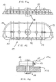
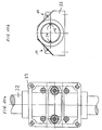
- the circulating ball shoe 10 shown in FIGS. 1a, b has an inner segment 11, around which balls 12 are arranged, which are enclosed by a housing 13.
- This housing 13 is on the Longitudinal side 14 opened, the balls 12 being prevented from falling out by a web 15 connected to the housing.
- the inner segment 11 can be adjusted by the adjusting eccentric 16 against a prism rail 17 (see FIG. 1c) with the desired accuracy.
- the recirculating ball shoe or the prism rail 17 can now move in length over the rolling balls 12 indefinitely.
- the housing 13 including webs 15 and the top and bottom 17a, b of the prism rail 17 are coated with a powder coating.
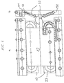
- Fig. 2 shows the revolving shoe 10 in question in an embodiment in which both longitudinal sides 14a and 14b are open, so that the balls 12 are accessible from the outside from both longitudinal sides and are each held against falling out by a web 15a, b.
- Fig. 2c shows the contact of a row of balls 12 on a prismatic track 17, which is also used for adjustment instead of the eccentric provided in Fig. 1a to c.
- the recirculating ball shoe has retaining screws 18.
- the housing 13, the webs 15a, b and the prismatic track 17 are coated over their entire area with powder coating.
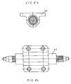
- Fig. 3 shows a double-sided ground prism rail 17, the groove-shaped grooves 19 are ground in each case on the narrow longitudinal sides 20.
- the prismatic track 17 contains one or more bores 21 - as required for fastening further components (not shown) and is coated on its surfaces 17a, b with a powder coating layer.
- the transfer table arrangement shown in FIGS. 4a and b essentially consists of a table 22 and ball circulation shoes 10 attached to it, which can be moved linearly along the longitudinal axis of a powder-coated prismatic track 17 together with the table 22.
- the preload or the contact pressure of the balls 12 can, as explained, be carried out via the adjusting eccentric 16.
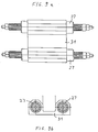
- 5a, b, 6a and 6b each show recirculating ball shoes 20 in which the recirculating ball is introduced by webs into two pipe deflection bends 23 which are connected to a straight piece of pipe.
- the recirculating ball shoes are arranged obliquely in such a way that the balls which are exposed on one long side lie in the running grooves 19 of a prism running rail 17 arranged in the center. Further correspondingly clamped rails 171 and 172 are provided on the opposite sides in each case (FIG. 6b).
- Fig. 7 shows a ball guide for a limited sliding path.
- This ball guide 24 consists of an inner shaft 25, the ball cage 26 with the balls 12 and the outer tube 27.
- the balls 12 roll on the corrugated groove 28 and the inner surface 29 of the outer tube 27.
- the tube 27 always covers half the way of the desired entire sliding length.
- the inner shaft has twelve raceways 28 for the balls, which are evenly distributed over the circumference and ground in the axial direction.
- the inner shaft and the outer tube have a hardness of RC 60 to 62 and are powder-coated.
- FIGS. 8a and b An installation example for the ball guide according to FIG. 7 is shown in FIGS. 8a and b.
- the outer tube 27 serves as a support for a likewise powder-coated bearing block 30, in the bore of which the shaft 27 is embedded.
- 9a and 9b show a corresponding arrangement of a double bearing block 31, the carrier of which are two outer tubes 27.
- 10a and 10b again show a ball guide for unlimited sliding paths, in which running on a round shaft 32 at least two recirculating ball shoes 10 are arranged in a housing 33, which can consist, for example, of a cast steel.
- the shaft 32 has two opposed hardened and ground grooves 34, in which the balls 12 roll.
- a torque can be transmitted from the housing 33 to the shaft 32 or vice versa by the running grooves 32 in the recirculating ball shoes 10.
- the housing 33 and the shaft 32 therefore form an accurate table guide.
- the housing 13, including the web 15, the prism rail 17, the table 22, the tube deflection bends 23, the outer tube 27, the shaft 25, the bearing blocks 30, 31 and the shafts 27, 32 or the housing 33 are at least powder-coated in the area freely accessible to the outside atmosphere, for which purpose commercially available powder-coating formulations can be used.
- the thickness of the powder coating is in each case 50 to 100 ⁇ m
- the material of the powder coating used is an epoxy polyester and / or polyurethane material which has been applied to the grounded workpiece by means of an electrostatic coating process.
- the powder coating was baked at baking temperatures between 160 and 200 ° C within a maximum of 10 minutes after the object temperature had been reached.
- the thickness of the powder coating applied depends on the time over which the electric field is applied.
- the advantage of the powder coatings used is that the starting materials used do not contain any solvents and therefore no waste is generated.
- the material is loaded using a spray gun and applied to the workpiece.
- the material can also be applied in places that are difficult to access because the electric field completely surrounds the workpiece.
- Material that is not applied to the workpiece is produced from the Spray chamber vacuumed and can be used again the next time you spray.
- the powder starting material will be supplied in a suitable mixture of resin, hardener, pigment and additives, in particular dyes, in a suitable homogeneous mixture and is commercially available.
Landscapes
- Engineering & Computer Science (AREA)
- General Engineering & Computer Science (AREA)
- Mechanical Engineering (AREA)
- Manufacturing & Machinery (AREA)
- Bearings For Parts Moving Linearly (AREA)
Applications Claiming Priority (2)
| Application Number | Priority Date | Filing Date | Title |
|---|---|---|---|
| DE4111544 | 1991-04-09 | ||
| DE19914111544 DE4111544A1 (de) | 1991-04-09 | 1991-04-09 | Kugelfuehrung |
Publications (1)
| Publication Number | Publication Date |
|---|---|
| EP0508317A1 true EP0508317A1 (fr) | 1992-10-14 |
Family
ID=6429186
Family Applications (1)
| Application Number | Title | Priority Date | Filing Date |
|---|---|---|---|
| EP92105773A Pending EP0508317A1 (fr) | 1991-04-09 | 1992-04-03 | Glissière à billes |
Country Status (2)
| Country | Link |
|---|---|
| EP (1) | EP0508317A1 (fr) |
| DE (1) | DE4111544A1 (fr) |
Cited By (2)
| Publication number | Priority date | Publication date | Assignee | Title |
|---|---|---|---|---|
| DE102006041116A1 (de) * | 2006-09-01 | 2008-03-20 | Bahr Modultechnik Gmbh | Positioniervorrichtung mit umhülltem Hohlprofil |
| EP1617092A3 (fr) * | 2004-07-14 | 2011-03-23 | Nsk Ltd. | Palier à guide linéaire |
Families Citing this family (2)
| Publication number | Priority date | Publication date | Assignee | Title |
|---|---|---|---|---|
| DE19843668A1 (de) * | 1998-09-23 | 2000-04-13 | Crown Simplimatic Maschinentec | Bewegungsvorrichtung mit M-Profil-Träger |
| DE102012221207A1 (de) * | 2012-11-20 | 2014-06-05 | Schaeffler Technologies Gmbh & Co. Kg | Profilschienenführung |
Citations (10)
| Publication number | Priority date | Publication date | Assignee | Title |
|---|---|---|---|---|
| US4005913A (en) * | 1975-01-08 | 1977-02-01 | Thomson Industries, Inc. | Linear motion bearing block |
| DE2656822A1 (de) * | 1976-12-15 | 1978-06-22 | Markus Spoetzl | Waelzlagerung |
| JPS57153767A (en) * | 1981-03-17 | 1982-09-22 | Ntn Toyo Bearing Co Ltd | Formation of lining layer on slide surface |
| WO1982003190A1 (fr) * | 1981-03-13 | 1982-09-30 | Linck Werner | Revetement combine et son procede de preparation |
| EP0218836A1 (fr) * | 1985-09-06 | 1987-04-22 | Gebrüder Honsberg GmbH | Guidage des chariots |
| JPH01242823A (ja) * | 1988-03-23 | 1989-09-27 | Yobea Rulon Kogyo Kk | 電蝕防止型転がり軸受 |
| EP0349918A2 (fr) * | 1988-07-02 | 1990-01-10 | E.A. Storz Gmbh & Co. Kg | Disposition de glissière, en particulier pour siège de voiture |
| DD282958A5 (de) * | 1989-05-02 | 1990-09-26 | Werkzeugmaschinenbau Fz | Gleitschiene aus haertbarem stahl zum gleitenden verschieben prismatischer werkstuecke |
| EP0391072A1 (fr) * | 1989-04-01 | 1990-10-10 | INA Wälzlager Schaeffler KG | Unité de guidage rectiligne à contact de roulement |
| JPH02261924A (ja) * | 1989-03-31 | 1990-10-24 | Nippon Seiko Kk | フィードユニット装置用ガイドレール |
-
1991
- 1991-04-09 DE DE19914111544 patent/DE4111544A1/de not_active Withdrawn
-
1992
- 1992-04-03 EP EP92105773A patent/EP0508317A1/fr active Pending
Patent Citations (10)
| Publication number | Priority date | Publication date | Assignee | Title |
|---|---|---|---|---|
| US4005913A (en) * | 1975-01-08 | 1977-02-01 | Thomson Industries, Inc. | Linear motion bearing block |
| DE2656822A1 (de) * | 1976-12-15 | 1978-06-22 | Markus Spoetzl | Waelzlagerung |
| WO1982003190A1 (fr) * | 1981-03-13 | 1982-09-30 | Linck Werner | Revetement combine et son procede de preparation |
| JPS57153767A (en) * | 1981-03-17 | 1982-09-22 | Ntn Toyo Bearing Co Ltd | Formation of lining layer on slide surface |
| EP0218836A1 (fr) * | 1985-09-06 | 1987-04-22 | Gebrüder Honsberg GmbH | Guidage des chariots |
| JPH01242823A (ja) * | 1988-03-23 | 1989-09-27 | Yobea Rulon Kogyo Kk | 電蝕防止型転がり軸受 |
| EP0349918A2 (fr) * | 1988-07-02 | 1990-01-10 | E.A. Storz Gmbh & Co. Kg | Disposition de glissière, en particulier pour siège de voiture |
| JPH02261924A (ja) * | 1989-03-31 | 1990-10-24 | Nippon Seiko Kk | フィードユニット装置用ガイドレール |
| EP0391072A1 (fr) * | 1989-04-01 | 1990-10-10 | INA Wälzlager Schaeffler KG | Unité de guidage rectiligne à contact de roulement |
| DD282958A5 (de) * | 1989-05-02 | 1990-09-26 | Werkzeugmaschinenbau Fz | Gleitschiene aus haertbarem stahl zum gleitenden verschieben prismatischer werkstuecke |
Non-Patent Citations (4)
| Title |
|---|
| PATENT ABSTRACTS OF JAPAN vol. 13, no. 577 (M-910)(3925) 20. Dezember 1989 & JP-A-1 242 823 ( YOBEA RULON KOGYO ) 27. September 1989 * |
| PATENT ABSTRACTS OF JAPAN vol. 15, no. 010 (M-1068)10. Januar 1991 & JP-A-2 261 924 ( NIPPON SEIKO ) 24. Oktober 1990 * |
| PATENT ABSTRACTS OF JAPAN vol. 6, no. 261 (C-141)21. Dezember 1982 & JP-A-57 153 767 ( NTN TOYO BEARING ) 22. September 1982 * |
| WORLD PATENTS INDEX LATEST Section Ch, Week 9109, Derwent Publications Ltd., London, GB; Class M, AN 91-058676 & DD-A-282 958 (FORSCH WERKZ MARX) 26. September 1990 * |
Cited By (3)
| Publication number | Priority date | Publication date | Assignee | Title |
|---|---|---|---|---|
| EP1617092A3 (fr) * | 2004-07-14 | 2011-03-23 | Nsk Ltd. | Palier à guide linéaire |
| DE102006041116A1 (de) * | 2006-09-01 | 2008-03-20 | Bahr Modultechnik Gmbh | Positioniervorrichtung mit umhülltem Hohlprofil |
| DE102006041116B4 (de) * | 2006-09-01 | 2012-05-03 | Bahr Modultechnik Gmbh | Positioniervorrichtung mit umhülltem Hohlprofil |
Also Published As
| Publication number | Publication date |
|---|---|
| DE4111544A1 (de) | 1992-10-15 |
Similar Documents
| Publication | Publication Date | Title |
|---|---|---|
| DE19542453A1 (de) | Vorrichtung zur Umwandlung einer Drehbewegung in eine Axialbewegung | |
| DE2941565C2 (de) | Kugelgewindetrieb | |
| EP1022478A1 (fr) | Guidage linéaire à éléments roulants | |
| DE69502774T2 (de) | Hochgeschwindigkeitslinearführung | |
| DE2729354A1 (de) | Kugellaufbahn | |
| EP0508317A1 (fr) | Glissière à billes | |
| DE69712000T2 (de) | Linearlagereinheit für eine kurvenförmige Bewegung | |
| EP0171700B1 (fr) | Palier à rouleaux ajustable | |
| DE4015205C1 (en) | Method of reinforcing gas turbine rotor - has balls forced against base surface of slot in rotor to compress it | |
| DE19619449A1 (de) | Linearführung | |
| DE19581261C1 (de) | Spieleinstellbares Linearlager | |
| EP1123164B1 (fr) | Dispositif pour appliquer et/ou repartir des substances liquides ou pateuses pour recouvrir des surfaces | |
| EP0622134B1 (fr) | Dispositif pour le graissage de pièces en forme de bandes ou de plaques | |
| DE102004051829A1 (de) | Linearführungs-Vorschubmodul mit Führungskörper sowie Ausleger hierfür | |
| DE102020211039A1 (de) | Lageranordnung | |
| EP0984181B1 (fr) | Rouleau à réglage de la flexion | |
| DE3817973C2 (fr) | ||
| DE2934365A1 (de) | Staurollenbahn. | |
| DE2332195A1 (de) | Stangenkopflagereinrichtung | |
| DE2454525A1 (de) | Radial verstellbare kugelbuechse | |
| EP0676553B1 (fr) | Palier linéaire à roulement | |
| DE4324838A1 (de) | Wälzringgewindetrieb | |
| DE2558196A1 (de) | Vorrichtung zur axialen fuehrung durch kugelberuehrung | |
| DE9407424U1 (de) | Linearführungseinrichtung | |
| DE102011017759A1 (de) | Abdeckung zur Aufnahme eines Profilschienenwagens |
Legal Events
| Date | Code | Title | Description |
|---|---|---|---|
| PUAI | Public reference made under article 153(3) epc to a published international application that has entered the european phase |
Free format text: ORIGINAL CODE: 0009012 |
|
| STAA | Information on the status of an ep patent application or granted ep patent |
Free format text: STATUS: THE APPLICATION HAS BEEN PUBLISHED |
|
| AK | Designated contracting states |
Kind code of ref document: A1 Designated state(s): PT |