EP0508142A2 - Lampe pouvant tourner - Google Patents
Lampe pouvant tourner Download PDFInfo
- Publication number
- EP0508142A2 EP0508142A2 EP92104248A EP92104248A EP0508142A2 EP 0508142 A2 EP0508142 A2 EP 0508142A2 EP 92104248 A EP92104248 A EP 92104248A EP 92104248 A EP92104248 A EP 92104248A EP 0508142 A2 EP0508142 A2 EP 0508142A2
- Authority
- EP
- European Patent Office
- Prior art keywords
- ring
- stop
- stop part
- end stop
- Prior art date
- Legal status (The legal status is an assumption and is not a legal conclusion. Google has not performed a legal analysis and makes no representation as to the accuracy of the status listed.)
- Withdrawn
Links
Images
Classifications
-
- F—MECHANICAL ENGINEERING; LIGHTING; HEATING; WEAPONS; BLASTING
- F21—LIGHTING
- F21V—FUNCTIONAL FEATURES OR DETAILS OF LIGHTING DEVICES OR SYSTEMS THEREOF; STRUCTURAL COMBINATIONS OF LIGHTING DEVICES WITH OTHER ARTICLES, NOT OTHERWISE PROVIDED FOR
- F21V17/00—Fastening of component parts of lighting devices, e.g. shades, globes, refractors, reflectors, filters, screens, grids or protective cages
- F21V17/10—Fastening of component parts of lighting devices, e.g. shades, globes, refractors, reflectors, filters, screens, grids or protective cages characterised by specific fastening means or way of fastening
- F21V17/18—Latch-type fastening, e.g. with rotary action
-
- F—MECHANICAL ENGINEERING; LIGHTING; HEATING; WEAPONS; BLASTING
- F21—LIGHTING
- F21S—NON-PORTABLE LIGHTING DEVICES; SYSTEMS THEREOF; VEHICLE LIGHTING DEVICES SPECIALLY ADAPTED FOR VEHICLE EXTERIORS
- F21S8/00—Lighting devices intended for fixed installation
- F21S8/02—Lighting devices intended for fixed installation of recess-mounted type, e.g. downlighters
-
- F—MECHANICAL ENGINEERING; LIGHTING; HEATING; WEAPONS; BLASTING
- F21—LIGHTING
- F21V—FUNCTIONAL FEATURES OR DETAILS OF LIGHTING DEVICES OR SYSTEMS THEREOF; STRUCTURAL COMBINATIONS OF LIGHTING DEVICES WITH OTHER ARTICLES, NOT OTHERWISE PROVIDED FOR
- F21V21/00—Supporting, suspending, or attaching arrangements for lighting devices; Hand grips
- F21V21/14—Adjustable mountings
- F21V21/30—Pivoted housings or frames
-
- F—MECHANICAL ENGINEERING; LIGHTING; HEATING; WEAPONS; BLASTING
- F21—LIGHTING
- F21V—FUNCTIONAL FEATURES OR DETAILS OF LIGHTING DEVICES OR SYSTEMS THEREOF; STRUCTURAL COMBINATIONS OF LIGHTING DEVICES WITH OTHER ARTICLES, NOT OTHERWISE PROVIDED FOR
- F21V21/00—Supporting, suspending, or attaching arrangements for lighting devices; Hand grips
- F21V21/02—Wall, ceiling, or floor bases; Fixing pendants or arms to the bases
- F21V21/04—Recessed bases
-
- F—MECHANICAL ENGINEERING; LIGHTING; HEATING; WEAPONS; BLASTING
- F21—LIGHTING
- F21V—FUNCTIONAL FEATURES OR DETAILS OF LIGHTING DEVICES OR SYSTEMS THEREOF; STRUCTURAL COMBINATIONS OF LIGHTING DEVICES WITH OTHER ARTICLES, NOT OTHERWISE PROVIDED FOR
- F21V27/00—Cable-stowing arrangements structurally associated with lighting devices, e.g. reels
Definitions
- the invention relates to a lamp with a retaining ring in which a rotating ring carrying a lamp holder can be rotated.
- Luminaires that allow light to be emitted in different directions are often equipped with a rotating ring to which the lamp holder is attached. Depending on the rotational position of the rotating ring, the light can be emitted in different directions.
- Typical examples of such rotatable luminaires are recessed spotlights that are built into ceilings or walls and are designed so that they do not radiate the light axially, but at an angle to the axial direction. The direction of radiation can be varied by rotating around the luminaire axis.
- Rotatable lights require a rotation limit in order to prevent the cables leading to the lamp holder from winding up and finally breaking or tearing when the rotation is unlimited. If a stop device is provided to prevent rotation, two cooperating stops must be provided for this. Each of these stops extends over a certain angular range, so that a rotation of the rotating ring or the lamp holder by 360 ° is no longer guaranteed. The sum of the circumferential angular extents of the two interacting stops must be subtracted from 360 °. If it is no longer possible to adjust the lamp over the range of a full revolution (360 °), the case may arise that the lamp is to be adjusted to an object that cannot be reached due to the rotation limit. With simple stops to limit the rotation, there is always a blind spot to which the lamp cannot be adjusted and which affects the applicability of the lamp, even if it is small.
- the invention has for its object to provide a rotatable lamp in which there is a rotation limit, but which allows a full rotation through 360 °.
- one of the rings of the retaining ring and rotating ring is provided with a rigid end stop, while the other ring has a flexible stop device, the stop part of which can assume two stable tilt positions.
- a tip of the sling interacts with the fixed end stop. Depending on the respective direction of rotation, this tip always assumes a trailing position, so that the ring which carries the stop part can be moved further in the direction of rotation than would be possible with the tip pointing forward.
- the fact that the tip of the stop member points upstream, ie against the direction of rotation of the ring in question, means that the ring can be rotated further by a certain amount.
- the end stop usually consists of a projection on one ring. However, it is also possible to provide a recess as an end stop.
- the invention enables a full 360 ° rotation to be achieved with simple means, with the formation of overlap areas for right and left rotation, these overlap areas representing the blind spot cover up.
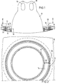
- the lamp shown has a retaining ring 11 to be installed in an opening of a suspended ceiling 10, which is mounted with clamping devices 12 in the ceiling opening.
- the retaining ring 11 is with a Provided inner flange 13 on which the rotary ring 14 is suspended.
- This rotary ring 14 is provided with pivotable slides 15 which overlap the flange 13 from the inside and secure the rotary ring 14 on the retaining ring 11 in the axial direction, although they allow the rotary ring 14 to rotate about its longitudinal axis.
- a bezel ring 16 is clamped under the rotating ring 14 and covers the rotating ring and the retaining ring on the visible side.
- the lamp holder 17 is fastened to the rotating ring 14. This consists of a reflector housing in which the lamps 18 are fastened. The attachment of the lamp holder 17 to the rotating ring 14 is not shown for reasons of clarity. However, the lamp holder 17 can be pivoted about the pivot axis 19 running parallel to the ring axis in order to be able to emit light not only in the axial direction but also at an angle to the axial direction. In order to direct the light in the desired spatial direction, the lamp holder 17 can also be rotated together with the rotating ring 14 around the ring axis. So that the wires leading to the lamp holders do not twist endlessly during this rotation, a rotation limiting device 20 is provided which is effective between the holding ring 11 and the rotating ring 14.
- the retaining ring 11 has a cylindrical ring wall 21, from which the inner flange 13 protrudes.
- This ring wall 21 encloses the ring wall 22 of the rotary ring 14.
- the axially projecting end stop 23 is provided as a projection under the flange 13.
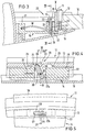
- the end stop 23 protrudes accordingly Fig. 4 from a depression 24 in front.
- the depression 24 merges at both ends through a transition 25 into the guide edge 26, which forms a guide surface for abutting the end of the ring wall 22 of the rotary ring 14.
- a pocket 36 is formed at one point in the annular wall 22, which is delimited radially on the outside and inside by the annular wall 22 and which is open at the top and bottom.
- the pocket 36 is delimited in the circumferential direction by the two end walls 27a and 27.
- the movable stop part 28 which is designed as an elongated flat slide which can move in the plane of the pocket 36 and which projects from the pocket 36 towards the flange 13 with a tip 29 at one end .
- a spring 30 acts on the stop part 28, which spring is designed here as a spiral spring and one end of which is fastened in a hole in the stop part 28. The other end of the spring 30 is firmly clamped in an inner ring wall 31 (FIG. 3) of the rotary ring 14.
- the spring 30 projects through an opening 32 in the outer ring wall 22 into the pocket 36. Their pretension is such that they endeavor to press the stop part 28 with the tip 29 against the guide edge 26 or against the flange 13.
- the stop part 28 can be rotated on the spring 30 or the spring 30 is torsional so that it allows the pivoting or rotation of the stop part 28 within a limited angular range.
- FIG. 4 shows the state that the rotary ring 14 reaches its end position when rotated in the direction of arrow 33.
- the crest 29 of the stop part 28 is pressed by the spring 30 into the depression 24 and there the crest 29 abuts the left flank of the fixed one End stop 23 of the retaining ring 11.
- the reference line 34 passing through the center of the pocket 36 is the 0 ° line of the rotating ring 14.
- the reference line 35 passing through the center of the end stop 23 is the 0 ° line of the retaining ring 11. It can be seen that in the state according to FIG. 4 the two reference lines 34 and 35 coincide.
- the crest 29 is clamped between the end stop 23 and the end wall 27 of the pocket 36, whereby it protrudes upward from the pocket.
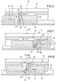
- Fig. 6 shows the state that the rotary ring 14 is rotated in the direction of arrow 37, that is in the opposite direction to arrow 33 of Fig. 4.
- the stop part 28 maintains its left inclined position until the crest 29 abuts the transition 25.
- the crest 29 is held in place and, when the rotary ring 14 is turned further, is pivoted into the right end position.
- the point of application of the spring 30 on the stop part 28 then shifts to the left in the pocket 36.
- the tip 29 now slides along the guide edge 26.
- FIG. 7 shows this state just before the rotary ring 14 has completed its full rotation and the stop member 28 penetrates into the depression 24 under the action of the spring 30.
- the crest 29 slides into the depression 24 and abuts there against the right flank of the fixed end stop 23, while it is in contact with the right end wall 27a of the pocket 36.
- the lower end of the stop part 28 is then in the vicinity of the left end wall 27.
- This final state which is reached after a complete 360 ° rotation of the rotary ring 14, is shown in FIG. 8. It can be seen that the reference line 34 of the rotary ring 14 then again coincides with the reference line 35 of the retaining ring 11, such as this was the case in the starting position according to FIG. 4.
- the stop part 28 is not rotatable about a fixed axis, but it adjusts itself freely together with the spring 30 in the pocket 36.
- the spring 30 only pushes the stop part upwards, that is in the direction of the guide edge 26.
- the guide edge 26 can serve as a slide bar for the ring wall 22, as is the case in the exemplary embodiment described. However, such a guide edge is not absolutely necessary.
- the end stop 23 can protrude from the flange 13 as the only elevation. In this case, the transitions 25 and 26 are not present. Starting from the position shown in FIG. 4, the stop part 28 would then remain in the inclined position shown there until, shortly before reaching the position shown in FIG. 8, it only swivels into the right tilt position after the tip 29 has hit the end stop 23 .
Landscapes
- Engineering & Computer Science (AREA)
- General Engineering & Computer Science (AREA)
- Non-Portable Lighting Devices Or Systems Thereof (AREA)
Applications Claiming Priority (2)
| Application Number | Priority Date | Filing Date | Title |
|---|---|---|---|
| DE19914111600 DE4111600C1 (fr) | 1991-04-10 | 1991-04-10 | |
| DE4111600 | 1991-04-10 |
Publications (2)
| Publication Number | Publication Date |
|---|---|
| EP0508142A2 true EP0508142A2 (fr) | 1992-10-14 |
| EP0508142A3 EP0508142A3 (en) | 1992-12-23 |
Family
ID=6429224
Family Applications (1)
| Application Number | Title | Priority Date | Filing Date |
|---|---|---|---|
| EP19920104248 Withdrawn EP0508142A3 (en) | 1991-04-10 | 1992-03-12 | Rotatable lamp |
Country Status (2)
| Country | Link |
|---|---|
| EP (1) | EP0508142A3 (fr) |
| DE (1) | DE4111600C1 (fr) |
Cited By (3)
| Publication number | Priority date | Publication date | Assignee | Title |
|---|---|---|---|---|
| EP2749815A1 (fr) * | 2012-12-28 | 2014-07-02 | Toshiba Lighting & Technology Corporation | Dispositif d'éclairage |
| EP2749814A1 (fr) * | 2012-12-28 | 2014-07-02 | Toshiba Lighting & Technology Corporation | Dispositif d'éclairage |
| WO2015101967A1 (fr) * | 2014-01-06 | 2015-07-09 | Koninklijke Philips N.V. | Mecanisme d'arrêt pour dispositif rotatif |
Families Citing this family (1)
| Publication number | Priority date | Publication date | Assignee | Title |
|---|---|---|---|---|
| DE202017105754U1 (de) * | 2017-09-22 | 2019-01-08 | Zumtobel Lighting Gmbh | Leuchte mit Anschlag |
Family Cites Families (4)
| Publication number | Priority date | Publication date | Assignee | Title |
|---|---|---|---|---|
| US2499250A (en) * | 1948-05-26 | 1950-02-28 | Kasher Sam | Electric lighting fixture |
| US2859333A (en) * | 1956-03-07 | 1958-11-04 | Rambusch Decorating Company | Lighting fixtures |
| DE7831828U1 (de) * | 1978-10-26 | 1979-02-15 | Hoffmeister-Leuchten Gmbh & Co Kg, 5880 Luedenscheid | Deckeneinbauleuchte |
| US4475147A (en) * | 1982-08-19 | 1984-10-02 | Mcgraw-Edison Company | Adjustable wall wash reflector assembly for a recess mounted lighting fixture |
-
1991
- 1991-04-10 DE DE19914111600 patent/DE4111600C1/de not_active Expired - Lifetime
-
1992
- 1992-03-12 EP EP19920104248 patent/EP0508142A3/de not_active Withdrawn
Cited By (6)
| Publication number | Priority date | Publication date | Assignee | Title |
|---|---|---|---|---|
| EP2749815A1 (fr) * | 2012-12-28 | 2014-07-02 | Toshiba Lighting & Technology Corporation | Dispositif d'éclairage |
| EP2749814A1 (fr) * | 2012-12-28 | 2014-07-02 | Toshiba Lighting & Technology Corporation | Dispositif d'éclairage |
| WO2015101967A1 (fr) * | 2014-01-06 | 2015-07-09 | Koninklijke Philips N.V. | Mecanisme d'arrêt pour dispositif rotatif |
| CN105980761A (zh) * | 2014-01-06 | 2016-09-28 | 飞利浦灯具控股公司 | 用于旋转设备的停止机构 |
| US10066778B2 (en) | 2014-01-06 | 2018-09-04 | Philips Lighting Holdingb.V. | Stop mechanism for a rotary device |
| CN105980761B (zh) * | 2014-01-06 | 2019-05-03 | 飞利浦灯具控股公司 | 用于旋转设备的停止机构 |
Also Published As
| Publication number | Publication date |
|---|---|
| EP0508142A3 (en) | 1992-12-23 |
| DE4111600C1 (fr) | 1992-09-10 |
Similar Documents
| Publication | Publication Date | Title |
|---|---|---|
| DE60129048T2 (de) | Beleuchtungskörper | |
| DE3809333C2 (fr) | ||
| DE19621432A1 (de) | Baugruppe zur Verbindung eines Betätigungsorgans mit einem Drehabsperrorgan | |
| DE3826676C2 (fr) | ||
| DE19733713C1 (de) | Leuchtengelenk | |
| DE3230414C2 (de) | Stößelschalter | |
| EP0508142A2 (fr) | Lampe pouvant tourner | |
| DE4228891A1 (de) | Einrichtung mit wenigstens zwei über eine Verstellschraube zueinander verstellbaren Bauteilen | |
| DE2618918C3 (de) | Vorrichtung zum Verändern der Lichtintensität einer Leuchte | |
| DE102005034436A1 (de) | Ringleuchte | |
| DE19546271A1 (de) | Scheinwerfer für Fahrzeuge | |
| DE3249401A1 (de) | Decken-einbauleuchte | |
| DE4421355C2 (de) | Verstellanordnung für einen Reflektor für einen Fahrzeugscheinwerfer | |
| EP0521267A2 (fr) | Lampe à distance réglable entre le réflecteur et la douille d'ampoule | |
| DE102005031173B4 (de) | Leuchte mit Schwenkvorrichtung | |
| EP0195980B1 (fr) | Dispositif de fixation pour support de lampe | |
| DE4342882C1 (de) | Einstellanordnung für einen oder mehrere Reflektoren für eine Kraftfahrzeug-Scheinwerfereinheit | |
| DE10015186B4 (de) | Objektivfassung | |
| EP1085257A1 (fr) | Projecteur d'éclairage avec verrouillage de l'articulation | |
| DE3432453C2 (fr) | ||
| DE102008017462B3 (de) | Langgestreckte Hängeleuchte | |
| DE4431444C1 (de) | Haltevorrichtung für eine lichtformende Vorsatzeinrichtung | |
| DE2516142C3 (de) | Drehkippgelenk für Leuchten | |
| DE2200540B2 (de) | Einrichtung zur Tempierung eines Geschoßzeitzünders | |
| DE2647422A1 (de) | Tragbare lampe, insbesondere gaslampe |
Legal Events
| Date | Code | Title | Description |
|---|---|---|---|
| PUAI | Public reference made under article 153(3) epc to a published international application that has entered the european phase |
Free format text: ORIGINAL CODE: 0009012 |
|
| AK | Designated contracting states |
Kind code of ref document: A2 Designated state(s): AT FR GB NL |
|
| PUAL | Search report despatched |
Free format text: ORIGINAL CODE: 0009013 |
|
| AK | Designated contracting states |
Kind code of ref document: A3 Designated state(s): AT FR GB NL |
|
| 17P | Request for examination filed |
Effective date: 19930204 |
|
| STAA | Information on the status of an ep patent application or granted ep patent |
Free format text: STATUS: THE APPLICATION HAS BEEN WITHDRAWN |
|
| 17Q | First examination report despatched |
Effective date: 19940411 |
|
| 18W | Application withdrawn |
Withdrawal date: 19940517 |