EP0507640A1 - Automatic machine for harvesting fruits - Google Patents
Automatic machine for harvesting fruits Download PDFInfo
- Publication number
- EP0507640A1 EP0507640A1 EP92400216A EP92400216A EP0507640A1 EP 0507640 A1 EP0507640 A1 EP 0507640A1 EP 92400216 A EP92400216 A EP 92400216A EP 92400216 A EP92400216 A EP 92400216A EP 0507640 A1 EP0507640 A1 EP 0507640A1
- Authority
- EP
- European Patent Office
- Prior art keywords
- tractor
- fruit
- tree
- trunk
- arm
- Prior art date
- Legal status (The legal status is an assumption and is not a legal conclusion. Google has not performed a legal analysis and makes no representation as to the accuracy of the status listed.)
- Withdrawn
Links
Images


Classifications
-
- A—HUMAN NECESSITIES
- A01—AGRICULTURE; FORESTRY; ANIMAL HUSBANDRY; HUNTING; TRAPPING; FISHING
- A01D—HARVESTING; MOWING
- A01D46/00—Picking of fruits, vegetables, hops, or the like; Devices for shaking trees or shrubs
- A01D46/26—Devices for shaking trees or shrubs; Fruit catching devices to be used therewith
- A01D2046/262—Collecting surfaces extended around a tree in order to catch the fruit
Definitions
- the present invention relates to an automatic machine intended for harvesting and collecting fruit from fruit trees, in particular plums.
- This machine is designed to be mounted on a tractor to collect fruit as the tractor advances continuously.
- the tractor carrying the automatic machine for dropping and collecting the fruit is associated with a second tractor moving along a trajectory parallel to its trajectory, on the other side of the row of trees, this second tractor being provided a conveyor belt and conveyor belts similar to those of the first tractor.
- the telescopic arm carrying the gripper element in the form of a clamp is moved in an angular movement by means of a scanning cylinder and it comprises a locking brake system which is released automatically. when tightening the clamp on the tree trunk.
- a horizontal conveyor belt with two directions of movement arranged on the lower edge of the reception mat and two lateral conveyor belts inclined to the horizontal bringing up the fruits harvested on the reception belts and transported by the horizontal belt, towards the receiving pallets provided on each of said tractors.
- the invention further provides on each tractor a sealing device mounted on one of the lateral edges of the horizontal conveyor belt, these devices coming to fall against the trunk of the tree enclosed by said gripping element in the form of pliers for ensure the continuity of the fruit receiving surface between the tractors.
- the machine which is the subject of the present invention is intended to ensure the harvesting of fruit is mounted on a tractor T1, this machine being designed so as to drop the fruits from a tree and to harvest them while by moving along a path that is parallel to the row of trees.
- This machine comprises a gripping element designated as a whole by the reference 10 which has the general shape of a clamp intended to grip the trunk 12 of the tree from which the fruit is to be harvested.
- This gripping element 10 is mounted at the end of a telescopic arm 14, the other end of which is fixed to the chassis of the tractor T1 by means of a hinge 16.
- the telescopic arm 14 is maneuvered from a cylinder 18 whose cylinder is articulated on the chassis of the tractor T1 as shown clearly seen in Figure 3. In the following description this cylinder 18 will be called a scanning cylinder.
- the gripping element 10 is mounted on a support 102 in the shape of a turret, the latter is guided in rotation by means of a bearing 104, the whole, substantially horizontal, is hung by a sleeve 111 from an axis 112 thus ensuring the angular scanning and the axial displacement of said gripping element, said support is fixed by known means to a set of telescopic arms 14, 14 ′, 18 which bear on one side of the chassis of the tractor, and on the other, to a frame having wheels 100 or tracks 101.
- the latter are optionally driving, the traction force being provided by a hydraulic unit coupled to one of the tractor PTOs.
- the telescopic arm 14 carries the gripping element 10 which consists of a fixed arm 20 mounted at the mobile end of the telescopic arm 14 and on which a mobile arm 22 is articulated.
- This mobile arm 22 is moved around its axis articulation 24 by means of a control cylinder 26.
- FIG. 3 clearly shows the manner in which the operation of the cylinder 26 makes it possible to move the moving element 22 apart or closer to it fixed 20 in order to grip the trunk 12 of the tree from which the fruit is to be harvested.
- the gripping element 10 is shown in the position in which it encloses the trunk 12 and in Figure 4 this element 10 is shown in the position in which the clamp consisting of the arms 20 and 22 is open.
- the invention provides protection means which, in this nonlimiting embodiment have been produced in the form of pneumatic wheels with axes vertical carried respectively by the movable arm 22 of the clamp (wheel 27) and by the fixed arm 20 (wheel 28-30).
- the gripping element 10 is mounted on a support 32 carried by a mobile assembly.
- the telescopic arm 14 is provided with a blocking brake system designated as a whole by the reference 38, this blocking brake being designed so as to be automatically released when the gripping element 10 in the form of a clamp grips the trunk 12 of the tree ( Figure 3).
- this blocking brake system 38 comprises an eccentric 40 bearing on a spring 42 whose opposite end of the telescopic arm 14 carries a friction surface 44, this eccentric 40 being mounted at the end of a rod 46 which is connected by a rod 48 to the movable arm 22 of the gripping element 10.
- the invention provides a vibrating system designated as a whole by the reference 50 and which is mounted on the arm fixed 20 of the gripping element 10 as clearly seen in Figure 3.
- this vibrating element is constituted by a disc 52 carrying an eccentric mass 54 constituting an unbalance, this disc being driven in rotation by means of a motor, for example a hydraulic pump 56.
- a rod-crank type system is preferred, the rod 105 being connected to the fixed and mobile arm 20 configuring the clamp, the other end of said connecting rod is fixed to crank 107 by means of axes 106, the latter have different radial anchoring points in order to vary the stroke of the connecting rod and therefore the amplitude of the shaking of the gripping element.
- the crank 107 is driven in a rotational movement thanks for example to a hydraulic group.
- the technology of the jacks 18 of angular positioning takes care of the correct indexing of the gripping element.
- the machine also includes means for collecting the fruits which fall from the tree when the trunk of the latter is rotated by the vibrating system 50.
- these means for collecting the fruit consist of at least one receiving mat 58 carried by a frame designated as a whole by the reference 60, this frame being mounted, at its lower part, on telescopic arms. such as 62 articulated on the chassis of the tractor and, at its upper part on arms such as 64 and 66.
- the receiving belt 58 comes to be positioned under the tree from which the fruit is to be collected.
- a second mat 58 ′ similar to the mat 58 which is mounted in the manner described above on a second tractor T2, associated according to the invention with the tractor T1 and which moves parallel to the path of the first tractor T1 on the other side of the row of trees as seen in Figure 2.
- each receiving mat 58 or 58 ′ comprises a horizontal conveyor belt 70, provided along its lower edge and which can be driven by an alternative translational movement and two lateral conveyor belts 72, 72 ′ inclined by relative to the horizontal so as to ensure the ascent of the fruits which are conveyed by the horizontal conveyor 70 and to bring them into the pallets such as 68.
- the assembly which is constituted by the receiving belts such as 58 and the conveyor belts 72, 72 ′ is mounted on the idler wheels 74, 74 ′.
- This assembly can be raised using jacks such as 76 which act on the arms 64 and 66 at the end of which is mounted the frame 60 supporting said assembly.
- jacks such as 76 which act on the arms 64 and 66 at the end of which is mounted the frame 60 supporting said assembly.
- Figure 1 there is shown in broken lines the raised position of this assembly.
- one of the support arms of the assembly described above is mounted telescopically.
- it is the rear arm 66 ( Figure 1) which can be moved using a cylinder 80 called a tilt cylinder. It is thus possible to correct the trajectory of the assembly allowing the fruit to be collected.
- a system of sealing tarpaulins is provided, mounted on the lateral edges of the belts. conveyors such as 70 and which is designed so as to fall back against the trunk 12 of the tree when the latter is vibrated by the vibrating system 50.
- each sheet such as 72 is mounted by one of its edges on the lateral edge of the frame 60 carrying the conveyor belt 70 and its other edge in the form of a flap 74 is designed so as to be applied against the surface of the trunk 12.
- a jack 76 makes it possible to lift each tarpaulin 72 using an articulated rod 88.
- a curtain is preferably formed from a plurality of flaps 108, 108 ′ having at least one articulation point 109, 109 ′ on the edge of the lateral chassis of the tractor T1 or T2, these flaps control by a linkage system 113, connected to the control unit of the machine, the bringing together or the spacing of the sealing device.
- This set thus conforms to a mattress of scales which adapts perfectly to the space to be filled located between the tree and said tractor T1 or T2.
- each tractor furthermore has fixed receiving surfaces 90, 90 ′ produced in the form of inclined planes which are mounted on a support respectively 92, 92 ′ fixed on each of the tractors T1 , T2.
- the operation remains broadly the same, however the differences in technology mentioned no longer require the use of a brake system of the gripping element, the sealing device deviates or approaches the trunk of the tree depending on the deviation encountered by the flaps and transmitted by the linkage to the machine control unit, which orders the jacks 72, 76 to move forward or backward.
- control jack systems described above, as well as the movements of the conveyor belts and of the moving parts can be controlled from a central unit, for example hydraulic, controlled by an electronic unit.
Abstract
Description
La présente invention est relative à une machine automatique destinée à assurer la récolte et le ramassage de fruits à partir d'arbres fruitiers, notamment de prunes. Cette machine est conçue de façon à être montée sur un tracteur afin de ramasser les fruits alors que le tracteur avance de façon continue.The present invention relates to an automatic machine intended for harvesting and collecting fruit from fruit trees, in particular plums. This machine is designed to be mounted on a tractor to collect fruit as the tractor advances continuously.
Cette invention concerne donc une machine automatique destinée à assurer la récolte de fruits à partir d'arbres fruitiers caractérisée en ce qu'elle comporte montés sur un tracteur :
- un élément de préhension, en forme de pince et positionné latéralement audit tracteur, qui est monté sensiblement horizontalement sur un support suspendu à un ensemble de bras télescopiques, pouvant être déplacé selon un mouvement angulaire par rapport à la trajectoire du tracteur, ledit élément de préhension comprenant un bras fixe supporté à l'extrémité dudit bras télescopique et un bras mobile articulé sur ledit bras fixe et déplacé par un vérin, lesdits bras fixe et mobile étant conçus de façon à enserrer le tronc dudit arbre et ils sont pourvus de moyens de protection afin de ne pas endommager le tronc de l'arbre qu'ils enserrent, tout cet ensemble étant supporté latéralement audit tracteur par un équipage mobile tel que des roues ou des chenilles éventuellement moteur.
- un système vibrant monté sur ledit élément de préhension pour entraîner ledit arbre en vibration afin d'en faire tomber les fruits après préhension de son tronc par ledit élément de préhension ;
- au moins un tapis de réception des fruits tombant de l'arbre porté par un cadre monté sur des bras télescopiques et muni de moyens de support, ledit tapis vient se positionner sous ledit arbre pour recueillir les fruits .
- a gripping element, in the form of a clamp and positioned laterally to said tractor, which is mounted substantially horizontally on a support suspended from a set of telescopic arms, which can be moved in an angular movement relative to the path of the tractor, said gripping element comprising a fixed arm supported at the end of said telescopic arm and a mobile arm articulated on said fixed arm and moved by a jack, said fixed and mobile arm being designed so as to grip the trunk of said tree and they are provided with protective means so as not to damage the trunk of the tree that they enclose, this whole set being supported laterally to said tractor by a mobile assembly such as wheels or possibly engine tracks.
- a vibrating system mounted on said gripping element for driving said shaft in vibration in order to cause the fruits to fall therefrom after gripping its trunk by said gripping element;
- at least one mat for receiving fruit falling from the tree carried by a frame mounted on telescopic arms and provided with support means, said mat is positioned under said tree to collect the fruit.
Selon la présente invention le tracteur portant la machine automatique pour faire tomber et recueillir les fruits est associée à un second tracteur se déplaçant selon une trajectoire parallèle à sa trajectoire, de l'autre côté de la rangée d'arbres, ce second tracteur étant muni d'un tapis de réception et de tapis transporteurs similaires à ceux du premier tracteur.According to the present invention, the tractor carrying the automatic machine for dropping and collecting the fruit is associated with a second tractor moving along a trajectory parallel to its trajectory, on the other side of the row of trees, this second tractor being provided a conveyor belt and conveyor belts similar to those of the first tractor.
Selon une autre caractéristique de la présente invention le bras télescopique portant l'élément préhenseur en forme de pince est déplacé d'un mouvement angulaire par l'intermédiaire d'un vérin de balayage et il comporte un système de frein de blocage qui se libère automatiquement lors du serrage de la pince sur le tronc de l'arbre.According to another characteristic of the present invention, the telescopic arm carrying the gripper element in the form of a clamp is moved in an angular movement by means of a scanning cylinder and it comprises a locking brake system which is released automatically. when tightening the clamp on the tree trunk.
Selon une autre caractéristique de la présente invention on prévoit un tapis transporteur horizontal à double sens de déplacement disposé sur le bord inférieur du tapis de réception et deux tapis transporteurs latéraux inclinés sur l'horizontale remontant les fruits récoltés sur les tapis de réception et transportés par le tapis horizontal, vers les palettes de réception prévues sur chacun desdits tracteurs.According to another characteristic of the present invention, there is provided a horizontal conveyor belt with two directions of movement arranged on the lower edge of the reception mat and two lateral conveyor belts inclined to the horizontal bringing up the fruits harvested on the reception belts and transported by the horizontal belt, towards the receiving pallets provided on each of said tractors.
L'invention prévoit en outre sur chaque tracteur un dispositif d'étanchéité montée sur l'un des bords latéraux du tapis transporteur horizontal, ces dispositifs venant se rabattre contre le tronc de l'arbre enserré par ledit élément de préhension en forme de pince pour assurer la continuité de la surface de réception des fruits entre les tracteurs.The invention further provides on each tractor a sealing device mounted on one of the lateral edges of the horizontal conveyor belt, these devices coming to fall against the trunk of the tree enclosed by said gripping element in the form of pliers for ensure the continuity of the fruit receiving surface between the tractors.
D'autres caractéristiques et avantages de la présente invention ressortiront de la description faite ci-après en référence aux dessins annexés qui en illustrent un exemple de réalisation dépourvu de tout caractère limitatif. Sur les dessins :
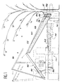
- la figure 1 est une vue schématique en élévation frontale représentant la machine de récolte selon la présente invention montée sur son tracteur et en position de fonctionnement ;
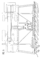
- la figure 2 est une vue similaire à la figure 1 mais à échelle plus réduite montrant la machine de récolte montée sur son tracteur associée à un second tracteur portant un tapis de réception des fruits similaire à celui prévu sur le premier tracteur ;
- la figure 3 est une vue schématique en plan de la figure 1 illustrant le fonctionnement de l'élément de préhension en forme de pince de la machine selon l'invention, cet élément étant représenté dans la position dans laquelle il enserre le tronc d'un arbre fruitier ;
- la figure 4 est une vue partielle schématique et en plan représentant l'élément de préhension dans sa position ouverte ;
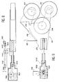
- la figure 5 est une vue en plan représentant l'un des tracteurs de la machine selon l'invention avec son tapis de réception des fruits récoltés et son dispositif d'étanchéité ;
- la figure 6 est une vue de dessus de la machine selon l'invention munie des autres moyens de réalisation de l'élément de préhension et du dispositif d'étanchéité entre l'arbre et le tracteur ;
- la figure 7 est une vue en élévation plane latérale de la machine selon le type de réalisation précédent avec un équipage mobile de propulsion.
- la figure 8 est une vue en élévation latérale de l'élément de préhension et de son support et
- la figure 9 est une vue de dessus de ces mêmes éléments.
- Figure 1 is a schematic front elevational view showing the harvesting machine according to the present invention mounted on its tractor and in the operating position;
- Figure 2 is a view similar to Figure 1 but on a smaller scale showing the harvesting machine mounted on its tractor associated with a second tractor carrying a fruit receiving mat similar to that provided on the first tractor;
- Figure 3 is a schematic plan view of Figure 1 illustrating the operation of the gripper-shaped gripper of the machine according to the invention, this element being shown in the position in which it encloses the trunk of a fruit tree ;
- Figure 4 is a schematic partial plan view showing the gripping member in its open position;
- FIG. 5 is a plan view showing one of the tractors of the machine according to the invention with its belt for receiving the harvested fruit and its sealing device;
- Figure 6 is a top view of the machine according to the invention provided with other means for producing the gripping element and the sealing device between the shaft and the tractor;
- Figure 7 is a side elevational view of the machine according to the previous embodiment with a movable propulsion system.
- FIG. 8 is a side elevation view of the gripping element and of its support and
- Figure 9 is a top view of these same elements.
En se référant aux dessins on voit que la machine objet de la présente invention est destinée à assurer la récolte de fruits est montée sur un tracteur T1, cette machine étant conçue de façon à faire tomber les fruits d'un arbre et à les récolter tout en se déplaçant selon une trajectoire qui est parallèle à la rangée d'arbres.Referring to the drawings, it can be seen that the machine which is the subject of the present invention is intended to ensure the harvesting of fruit is mounted on a tractor T1, this machine being designed so as to drop the fruits from a tree and to harvest them while by moving along a path that is parallel to the row of trees.
Cette machine comporte un élément de préhension désigné dans son ensemble par la référence 10 qui présente la forme générale d'une pince destinée à enserrer le tronc 12 de l'arbre dont on veut récolter les fruits. Cet élément de préhension 10 est monté à l'extrémité d'un bras télescopique 14 dont l'autre extrémité est fixée au chassis du tracteur T1 par l'intermédiaire d'une articulation 16. Le bras télescopique 14 est manoeuvré à partir d'un vérin 18 dont le cylindre est articulé sur le chassis du tracteur T1 comme on le voit clairement sur la figure 3. Dans la description qui suit ce vérin 18 sera appelé vérin de balayage.This machine comprises a gripping element designated as a whole by the
Selon un exemple de réalisation préféré (se reporter aux figures 5, 7, 8 et 9), l'élément de préhension 10 est monté sur un support 102 en forme de tourelle, celle-ci est guidée en rotation par l'intermédiaire d'un roulement 104, le tout, sensiblement horizontal, est pendu par une douille 111 à un axe 112 assurant ainsi le balayage angulaire et le déplacement axial dudit élément de préhension, cedit support est fixé par des moyens connus à un ensemble de bras télescopiques 14, 14′, 18 qui prennent appui sur l'un des côtés au châssis du tracteur, et sur l'autre, à un bâti disposant de roues 100 ou de chenilles 101. Ces dernières sont éventuellement motrices, la force de traction étant fournie par un groupe hydraulique accouplé à l'une des prises de force du tracteur.According to a preferred embodiment (see Figures 5, 7, 8 and 9), the
Le bras télescopique 14 porte l'élément de préhension 10 qui est constitué d'un bras fixe 20 monté à l'extrémité mobile du bras télescopique 14 et sur lequel est articulé un bras mobile 22. Ce bras mobile 22 est déplacé autour de son axe d'articulation 24 par l'intermédiaire d'un vérin de commande 26. L'examen de la figure 3 montre clairement la façon selon laquelle la manoeuvre du vérin 26 permet d'écarter ou de rapprocher l'élément mobile 22 de l'élément fixe 20 afin de venir enserrer le tronc 12 de l'arbre dont on veut récolter les fruits. Sur la figure 3, l'élément de préhension 10 est représenté dans la position dans laquelle il enserre le tronc 12 et sur la figure 4 cet élément 10 est représenté dans la position dans laquelle la pince constituée des bras 20 et 22 est ouverte. Afin de ne pas endommager le tronc de l'arbre, l'invention prévoit des moyens de protection qui, dans cet exemple de réalisation non limitatif ont été réalisés sous la forme de roues pneumatiques à axes verticaux portées respectivement par le bras mobile 22 de la pince (roue 27) et par le bras fixe 20 (roue 28-30).The
L'élément de préhension 10 est monté sur un support 32 porté par un équipage mobile.The
Le bras télescopique 14 est muni d'un système de frein de blocage désigné dans son ensemble par la référence 38, ce frein de blocage étant conçu de façon à être automatiquement libéré lorsque l'élément de préhension 10 en forme de pince enserre le tronc 12 de l'arbre (figure 3). Dans cet exemple de réalisation ce système de frein de blocage 38 comporte un excentrique 40 prenant appui sur un ressort 42 dont l'extrémité en regard du bras télescopique 14 porte une surface de friction 44, cet excentrique 40 étant monté à l'extrémité d'une tige 46 qui est reliée par une tringle 48 au bras mobile 22 de l'élément de préhension 10. Ainsi lorsque le bras mobile 26 se referme contre le bras fixe 20 en enserrant le tronc 12, l'excentrique 40 sous l'action de la tringle 48 et de la tige 46, libère le ressort 42 qui se détend en relachant le frein 38 (figure 3). Lorsque la pince est ouverte (figure 4) la traction exercée sur la tige 48 par le bras 22 actionne le frein 38 qui bloque le bras télescopique 14.The
Afin de faire tomber les fruits de l'arbre lorsque son tronc 12 est maintenu enserré dans la pince de l'élément de préhension 10, l'invention prévoit un système vibrant désigné dans son ensemble par la référence 50 et qui est monté sur le bras fixe 20 de l'élément de préhension 10 ainsi qu'on le voit clairement sur la figure 3. Dans cet exemple de réalisation cet élément vibrant est constitué par un disque 52 portant une masse excentrée 54 constituant un balourd, ce disque étant entraîné en rotation par l'intermédiaire d'un moteur par exemple une pompe hydraulique 56.In order to make the fruit fall from the tree when its
Selon un autre mode de réalisation du système vibrant (se référer aux figures 6, 8, 9), on préfère un système de type bielle-manivelle, la bielle 105 étant reliée au bras fixe 20 et mobile 22 configurant la pince, l'autre extrémité de ladite bielle est fixée sur manivelle 107 par l'intermédiaire d'axes 106, ces derniers possèdent des points d'ancrage radiaux différents afin de varier la course de la bielle et donc l'amplitude du secouement de l'élément de préhension. La manivelle 107 est animée d'un mouvement de rotation grâce par exemple à un groupe hydraulique. Dans cet exemple de réalisation particulier, il n'y a pas nécessité de freiner l'élément de préhension dans sa course, la technologie des vérins 18 de positionnement angulaire se charge de l'indexation correcte de l'élément de préhension.According to another embodiment of the vibrating system (refer to Figures 6, 8, 9), a rod-crank type system is preferred, the
La machine comporte également des moyens pour recueillir les fruits qui tombent de l'arbre lorsque le tronc de ce dernier est entraîné en rotation par le système vibrant 50.The machine also includes means for collecting the fruits which fall from the tree when the trunk of the latter is rotated by the vibrating
Dans cet exemple de réalisation non limitatif, ces moyens de recueil des fruits sont constitués par au moins un tapis de réception 58 porté par un cadre désigné dans son ensemble par la référence 60, ce cadre étant monté, à sa partie inférieure sur des bras télescopiques tels que 62 articulés sur le chassis du tracteur et, à sa partie supérieure sur des bras tels que 64 et 66. Comme on le voit sur les dessins le tapis de réception 58 vient se positionner sous l'arbre dont on veut recueillir les fruits. Selon la présente invention on prévoit un second tapis 58′ similaire au tapis 58 qui est monté de la manière décrite ci-dessus sur un second tracteur T2, associé selon l'invention au tracteur T1 et qui se déplace parallèlement à la trajectoire du premier tracteur T1 de l'autre côté de la rangée d'arbres comme on le voit sur la figure 2.In this nonlimiting exemplary embodiment, these means for collecting the fruit consist of at least one receiving
Les tapis de réception tels que 58 et 58′ sont associés à des tapis transporteurs permettant de recueillir les fruits et de les acheminer dans des palettes telles que 68 qui sont portées par les tracteurs T1 et T2. Dans cet exemple de réalisation chaque tapis de réception 58 ou 58′ comportent un tapis transporteur horizontal 70, prévu le long de son bord inférieur et qui peut être animé d'un déplacement de translation alternative et deux tapis transporteurs latéraux 72, 72′ inclinés par rapport à l'horizontale de manière à assurer la remontée des fruits qui sont acheminés par le transporteur horizontal 70 et à les amener dans les palettes telles que 68.The receiving belts such as 58 and 58 ′ are associated with conveyor belts making it possible to collect the fruits and to convey them in pallets such as 68 which are carried by the tractors T1 and T2. In this exemplary embodiment, each receiving
L'ensemble qui est constitué par les tapis de réception tels que 58 et les tapis transporteurs 72, 72′ est monté sur les roues folles 74, 74′. Cet ensemble peut être relevé à l'aide de vérins tels que 76 qui agissent sur les bras 64 et 66 à l'extrémité desquels est monté le cadre 60 supportant ledit ensemble. Sur la figure 1 on a représenté en traits mixtes la position relevée de cet ensemble.The assembly which is constituted by the receiving belts such as 58 and the
Selon la présente invention, l'un des bras de support de l'ensemble décrit ci-dessus est monté télescopique. Dans cet exemple il s'agit du bras arrière 66 (figure 1) qui peut être déplacé à l'aide d'un vérin 80 appelé vérin de dévers. Il est ainsi possible de corriger la trajectoire de l'ensemble permettant de recueillir les fruits.According to the present invention, one of the support arms of the assembly described above is mounted telescopically. In this example it is the rear arm 66 (Figure 1) which can be moved using a
Afin d'assurer la continuité de la surface de réception, constituée par les tapis de réception tels que 58, 58′, entre les deux tracteurs T1 et T2, on prévoit un système de bâches d'étanchéité, monté sur les bords latéraux des tapis transporteurs tels que 70 et qui est conçu de manière à venir se rabattre contre le tronc 12 de l'arbre lorsque ce dernier est entraîné en vibration par le système vibrant 50.In order to ensure the continuity of the receiving surface, constituted by the receiving belts such as 58, 58 ′, between the two tractors T1 and T2, a system of sealing tarpaulins is provided, mounted on the lateral edges of the belts. conveyors such as 70 and which is designed so as to fall back against the
Dans l'exemple de réalisation illustré par les figures 1 et 2 chaque bâche telle que 72 est montée par l'un de ses bords sur le bord latéral du cadre 60 portant le tapis transporteur 70 et son autre bord en forme de volet 74 est conçu de façon à venir s'appliquer contre la surface du tronc 12. Un vérin 76 permet d'assurer le relevage de chaque bâche 72 à l'aide d'une tige articulée 88.In the embodiment illustrated in FIGS. 1 and 2, each sheet such as 72 is mounted by one of its edges on the lateral edge of the
Selon un autre mode de réalisation du dispositif d'étanchéité (cf. figure 5), on constitue préférentiellement un rideau à partir d'une pluralité de volets 108, 108′ possédant au moins un point d'articulation 109, 109′ sur le bord du châssis latéral du tracteur T1 ou T2, ces volets commandent par un système de tringlerie 113, connecté à l'unité de commande de la machine, le rapprochement ou l'écartement du dispositif d'étanchéité. Cet ensemble conforme ainsi un matelas d'écailles qui s'adapte parfaitement à l'espace à combler situé entre l'arbre et ledit tracteur T1 ou T2.According to another embodiment of the sealing device (cf. FIG. 5), a curtain is preferably formed from a plurality of
Afin d'éviter toute perte de fruits lors de la récolte chaque tracteur comporte en outre des surfaces fixes de réception 90, 90′ réalisées sous la forme de plans inclinés qui sont montés sur un support respectivement 92, 92′ fixé sur chacun des tracteurs T1, T2.In order to avoid any loss of fruit during the harvest, each tractor furthermore has fixed receiving surfaces 90, 90 ′ produced in the form of inclined planes which are mounted on a support respectively 92, 92 ′ fixed on each of the tractors T1 , T2.
Le fonctionnement de la machine selon l'invention est le suivant pour le premier mode de réalisation (cf. figures 1, 2, 3 et 4) :
- les tracteurs T1 et T2 se déplacent de façon continue et selon des trajectoires parallèles entre les rangées d'arbres fruitiers. Lors de ces déplacements et avant préhension d'un tronc l'élément de préhension 10 est en position ouverte et le bras télescopique 14 est maintenu bloqué par le système de frein 38. Le vérin de balayage 18 permet de régler la position de l'élément de préhension 10 par rapport à la rangée d'arbres ;
- lorsque l'élément de préhension 10 vient s'appliquer sur le tronc 12 d'un arbre, les tracteurs continuant leur progression, la pince constituée par les
bras 20 et 22 se referme sur le tronc 12 sous la commande du vérin 26 enserrant ainsi le tronc 12. Simultanément le frein 38 est débloqué par action de la tige de commande 48 sur lebras 46 et le bras télescopique 14 est libéré ce qui lui permet de suivre le déplacement relatif de l'arbre par rapport aux tracteurs, lorque ceux-ci poursuivent leur avance ; - dès que le tronc 12 de l'arbre est enserré dans l'élément de préhension 10 le système vibrant 50 entre en action mettant l'arbre en vibration et faisant ainsi tomber les fruits. Ceux ci tombent alors sur la surface de réception consituée par les tapis de réception 58, 58′, les bâches 72, 72′ et les surfaces de réception
complémentaire - les fruits ainsi receuillis descendent le long des tapis de réception 58, 58′ pour être acheminés par les tapis transporteurs 70, 72
et 72′ dans les palettes telles que 68 prévues sur chaque tracteur T1 et T2. Selon l'invention, ce transfert dans les palettes 68 s'effectuent par l'intermédiaire de goulottes telles que 94′ qui sont pourvues de ventilateurs 110 de manière à éjecter les feuilles.
- the T1 and T2 tractors move continuously and in parallel paths between the rows of fruit trees. During these movements and before gripping a trunk, the gripping
element 10 is in the open position and thetelescopic arm 14 is kept blocked by thebrake system 38. Thescanning cylinder 18 makes it possible to adjust the position of thegripping element 10 relative to the row of shafts; - when the
gripping element 10 is applied to thetrunk 12 of a tree, the tractors continuing their progression, the clamp formed by thearms trunk 12 under the control of thejack 26 thus enclosing thetrunk 12. Simultaneously thebrake 38 is released by action of thecontrol rod 48 on thearm 46 and thetelescopic arm 14 is released which allows it to follow the relative movement of the shaft relative to the tractors, when these continue their advance; - as soon as the
trunk 12 of the tree is enclosed in thegripping element 10 the vibratingsystem 50 comes into action putting the tree in vibration and thus causing the fruit to fall. These then fall on the receiving surface constituted by the receivingbelts tarpaulins - the fruits thus collected descend along the receiving
belts conveyor belts pallets 68 is effected by means of chutes such as 94 ′ which are provided withfans 110 so as to eject the sheets.
Pour le second mode de réalisation rencontré (cf. figures 5, 6, 7, 8 et 9), le fonctionnement reste globalement le même, néanmoins les différences de technologie évoquées ne nécessitent plus l'emploi d'un système de frein de l'élément de préhension, le dispositif d'étanchéité s'écarte ou se rapproche du tronc de l'arbre en fonction de l'écart rencontré par les volets et transmis par la tringlerie à l'unité de contrôle de la machine, ce qui ordonne aux vérins 72, 76 un mouvement d'avancée ou de recul.For the second embodiment encountered (cf. FIGS. 5, 6, 7, 8 and 9), the operation remains broadly the same, however the differences in technology mentioned no longer require the use of a brake system of the gripping element, the sealing device deviates or approaches the trunk of the tree depending on the deviation encountered by the flaps and transmitted by the linkage to the machine control unit, which orders the
La description faite ci-dessus de la machine selon l'invention montre que cette dernière fonctionne de façon totalement automatique alors que les tracteurs T1 et T2 se déplacent en continu.The description given above of the machine according to the invention shows that the latter operates fully automatically while the tractors T1 and T2 move continuously.
Bien entendu les divers systèmes de vérins de commande décrits ci-dessus ainsi que les déplacements des tapis transporteurs et des équipages mobiles peuvent être commandés à partir d'une unité centrale par exemple hydraulique piloté par un boîtier électronique.Of course, the various control jack systems described above, as well as the movements of the conveyor belts and of the moving parts can be controlled from a central unit, for example hydraulic, controlled by an electronic unit.
Il demeure bien entendu que la présente invention n'est pas limitée à l'exemple de réalisation décrit et représenté ici mais qu'elle en englobe toutes les variantes.It remains to be understood that the present invention is not limited to the embodiment described and shown here but that it encompasses all variants thereof.
Claims (13)
Applications Claiming Priority (2)
| Application Number | Priority Date | Filing Date | Title |
|---|---|---|---|
| FR9104049A FR2674725A1 (en) | 1991-04-03 | 1991-04-03 | AUTOMATIC MACHINE FOR HARVESTING FRUIT. |
| FR9104049 | 1991-04-03 |
Publications (1)
| Publication Number | Publication Date |
|---|---|
| EP0507640A1 true EP0507640A1 (en) | 1992-10-07 |
Family
ID=9411430
Family Applications (1)
| Application Number | Title | Priority Date | Filing Date |
|---|---|---|---|
| EP92400216A Withdrawn EP0507640A1 (en) | 1991-04-03 | 1992-01-28 | Automatic machine for harvesting fruits |
Country Status (2)
| Country | Link |
|---|---|
| EP (1) | EP0507640A1 (en) |
| FR (1) | FR2674725A1 (en) |
Cited By (7)
| Publication number | Priority date | Publication date | Assignee | Title |
|---|---|---|---|---|
| FR2704715A1 (en) * | 1993-03-29 | 1994-11-10 | Gaubille Gaec | Machine for continuously mechanically picking up fruit and especially but not exclusively plums |
| FR2718322A1 (en) * | 1994-04-12 | 1995-10-13 | Dreux Maurice | Aid for removal and collection of fruit |
| ES2110343A1 (en) * | 1994-09-27 | 1998-02-01 | Cusine Barber Manuel | Machine for dislodging and gathering fruit from trees |
| ES2249070A1 (en) * | 2002-06-14 | 2006-03-16 | Automatismos Y Tecnicas Agricolas S.L.L. | Integral system for collecting arboreal product, has chassis of support with axis and wheel, and fan or umbrella placed on movable structure, where movement of structure is made in perpendicular direction until reaching trunk of tree |
| US7306018B2 (en) | 2002-12-13 | 2007-12-11 | Caterpillar Inc. | Tree harvesting apparatus |
| CN102656998A (en) * | 2012-03-25 | 2012-09-12 | 山东理工大学 | Push-rocking type Chinese date classifying harvester |
| CN108338007A (en) * | 2018-04-20 | 2018-07-31 | 西安建筑科技大学 | A kind of vibrating type fruit picker and picking method |
Citations (4)
| Publication number | Priority date | Publication date | Assignee | Title |
|---|---|---|---|---|
| US3248865A (en) * | 1965-05-10 | 1966-05-03 | William A Gerrans | Fruit and nut harvester |
| US3896612A (en) * | 1973-11-14 | 1975-07-29 | Research Corp | Fruit harvester |
| EP0010203A1 (en) * | 1978-09-26 | 1980-04-30 | THE UNITED STATES OF AMERICA as represented by the Secretary United States Department of Commerce | Mechanical shaker assembly for continuous harvesting of fruit |
| US4986065A (en) * | 1990-01-19 | 1991-01-22 | Ira Compton | Agricultural harvester |
-
1991
- 1991-04-03 FR FR9104049A patent/FR2674725A1/en not_active Withdrawn
-
1992
- 1992-01-28 EP EP92400216A patent/EP0507640A1/en not_active Withdrawn
Patent Citations (4)
| Publication number | Priority date | Publication date | Assignee | Title |
|---|---|---|---|---|
| US3248865A (en) * | 1965-05-10 | 1966-05-03 | William A Gerrans | Fruit and nut harvester |
| US3896612A (en) * | 1973-11-14 | 1975-07-29 | Research Corp | Fruit harvester |
| EP0010203A1 (en) * | 1978-09-26 | 1980-04-30 | THE UNITED STATES OF AMERICA as represented by the Secretary United States Department of Commerce | Mechanical shaker assembly for continuous harvesting of fruit |
| US4986065A (en) * | 1990-01-19 | 1991-01-22 | Ira Compton | Agricultural harvester |
Cited By (8)
| Publication number | Priority date | Publication date | Assignee | Title |
|---|---|---|---|---|
| FR2704715A1 (en) * | 1993-03-29 | 1994-11-10 | Gaubille Gaec | Machine for continuously mechanically picking up fruit and especially but not exclusively plums |
| FR2718322A1 (en) * | 1994-04-12 | 1995-10-13 | Dreux Maurice | Aid for removal and collection of fruit |
| ES2110343A1 (en) * | 1994-09-27 | 1998-02-01 | Cusine Barber Manuel | Machine for dislodging and gathering fruit from trees |
| ES2249070A1 (en) * | 2002-06-14 | 2006-03-16 | Automatismos Y Tecnicas Agricolas S.L.L. | Integral system for collecting arboreal product, has chassis of support with axis and wheel, and fan or umbrella placed on movable structure, where movement of structure is made in perpendicular direction until reaching trunk of tree |
| US7306018B2 (en) | 2002-12-13 | 2007-12-11 | Caterpillar Inc. | Tree harvesting apparatus |
| CN102656998A (en) * | 2012-03-25 | 2012-09-12 | 山东理工大学 | Push-rocking type Chinese date classifying harvester |
| CN102656998B (en) * | 2012-03-25 | 2014-07-30 | 山东理工大学 | Push-rocking type Chinese date classifying harvester |
| CN108338007A (en) * | 2018-04-20 | 2018-07-31 | 西安建筑科技大学 | A kind of vibrating type fruit picker and picking method |
Also Published As
| Publication number | Publication date |
|---|---|
| FR2674725A1 (en) | 1992-10-09 |
Similar Documents
| Publication | Publication Date | Title |
|---|---|---|
| EP0270469B1 (en) | Robotic machine, especially for harvesting fruits | |
| FR2556925A1 (en) | MACHINE FOR HARVESTING CAMOMILE FLOWER | |
| EP0507640A1 (en) | Automatic machine for harvesting fruits | |
| FR2628933A1 (en) | Vegetable seed and harvester - has orienting fingers, conveyor system and first and second cutter assemblies to collect, cut and trim stems and heads of crop | |
| EP0249562A1 (en) | Method and device for removing a hood from a pallet and unloading the same | |
| FR2681215A1 (en) | Machine for gathering melons | |
| EP0358563A1 (en) | Machine for harvesting berries and especially grapes | |
| FR2553969A1 (en) | Device for felling trees | |
| EP3413700B1 (en) | Device for collecting plants | |
| EP0406953A1 (en) | Harvester | |
| FR1464346A (en) | Advanced sugar cane harvester | |
| FR2719190A1 (en) | Machine for removing cut vine shoots | |
| FR2579062A1 (en) | Device for transmitting vibration to a shaft for mechanically harvesting fruit | |
| FR2551622A1 (en) | Machine for harvesting berries, a grape harvesting machine in particular | |
| FR2868905A1 (en) | Agricultural machine e.g. pick up, for self-propelled chopper blower, has foldable worm units disposed transversally in work position, and folded in rest position, where units are driven individually at their opposite free ends | |
| EP0098824A1 (en) | Farm machinery | |
| EP0016712B1 (en) | Machine for deleafing and topping beets or similar plants | |
| EP0015843A1 (en) | Beet gatherer and loader with pivoting bin | |
| BE845605A (en) | MACHINE FOR LOADING TUBERS, IN PARTICULAR, BEET, WINDOWS | |
| FR2664465A1 (en) | Improved device making it possible to harvest fruit (grapes) automatically | |
| WO1988005403A1 (en) | Method and device for taking one by one bags from a pile of bags and for placing them in a predetermined position | |
| FR2537826A1 (en) | Machine for harvesting plants in rows | |
| FR2729818A1 (en) | Automatic machine for shaking tree trunks to ensure fruit falls | |
| FR2778526A1 (en) | Machine for harvesting and bundling agricultural products | |
| FR2570245A1 (en) | TRACTOR FOR CARRYING AGRICULTURAL EQUIPMENT, IN PARTICULAR A TAKE-OFF AND HARVESTER UNIT AND A DEVICE FOR TRANSFERRING BEETS ON A SIDE VEHICLE |
Legal Events
| Date | Code | Title | Description |
|---|---|---|---|
| PUAI | Public reference made under article 153(3) epc to a published international application that has entered the european phase |
Free format text: ORIGINAL CODE: 0009012 |
|
| AK | Designated contracting states |
Kind code of ref document: A1 Designated state(s): DE ES FR GR IT PT |
|
| STAA | Information on the status of an ep patent application or granted ep patent |
Free format text: STATUS: THE APPLICATION IS DEEMED TO BE WITHDRAWN |
|
| 18D | Application deemed to be withdrawn |
Effective date: 19930408 |