EP0506882B1 - Rechtwinkelige parabolische reflektorsysteme - Google Patents
Rechtwinkelige parabolische reflektorsysteme Download PDFInfo
- Publication number
- EP0506882B1 EP0506882B1 EP91903020A EP91903020A EP0506882B1 EP 0506882 B1 EP0506882 B1 EP 0506882B1 EP 91903020 A EP91903020 A EP 91903020A EP 91903020 A EP91903020 A EP 91903020A EP 0506882 B1 EP0506882 B1 EP 0506882B1
- Authority
- EP
- European Patent Office
- Prior art keywords
- reflecting surface
- reflector
- source
- axis
- focal point
- Prior art date
- Legal status (The legal status is an assumption and is not a legal conclusion. Google has not performed a legal analysis and makes no representation as to the accuracy of the status listed.)
- Expired - Lifetime
Links
Images


Classifications
-
- G—PHYSICS
- G02—OPTICS
- G02B—OPTICAL ELEMENTS, SYSTEMS OR APPARATUS
- G02B5/00—Optical elements other than lenses
- G02B5/08—Mirrors
- G02B5/10—Mirrors with curved faces
-
- F—MECHANICAL ENGINEERING; LIGHTING; HEATING; WEAPONS; BLASTING
- F21—LIGHTING
- F21V—FUNCTIONAL FEATURES OR DETAILS OF LIGHTING DEVICES OR SYSTEMS THEREOF; STRUCTURAL COMBINATIONS OF LIGHTING DEVICES WITH OTHER ARTICLES, NOT OTHERWISE PROVIDED FOR
- F21V7/00—Reflectors for light sources
- F21V7/04—Optical design
- F21V7/09—Optical design with a combination of different curvatures
-
- F—MECHANICAL ENGINEERING; LIGHTING; HEATING; WEAPONS; BLASTING
- F21—LIGHTING
- F21Y—INDEXING SCHEME ASSOCIATED WITH SUBCLASSES F21K, F21L, F21S and F21V, RELATING TO THE FORM OR THE KIND OF THE LIGHT SOURCES OR OF THE COLOUR OF THE LIGHT EMITTED
- F21Y2103/00—Elongate light sources, e.g. fluorescent tubes
Definitions
- the invention relates to a reflector system. More specifically the invention relates to a reflector system including a reflector for converting a line source or sink into a point source or sink.
- Parabolic reflectors have hitherto been used as an efficient means of converting a parallel beam of radiation to a point known as the focal point of the reflector. This is the way the radar antenna, microwave dish, long range telescopes and search lights are designed.
- a point source theoretically with no physical dimension should be placed at the focal point of the parabolic reflector.
- the smallness of the point source and the intensity of the source trades off with power input capability, and flux density with materials due primarily to heat.
- the search light the limitation is the electric arc spot size and current density.
- tungsten filament lamps are limited by the melting temperature of tungsten and the filament length.
- Spark sources can be better than most point sources but cannot be a continuous source; besides, the source still has a finite dimension.
- a point source is being filtered by spatial filters such as a pin hole. This cuts down the intensity of the source and still has the resolution limited by the dimension of the pin hole.
- the dimension of the linear array of detectors operating in-phase will be better than a single detector collecting signals at a point source, which will make it very difficult to single out signal from white noises. All this is due to the limitations of the traditional parabolic geometry.
- the optical resolution of the light sources limits the line width of lithography when used to shrink printed circuit to a micro chip; 2) the optical resolution limits the resolution of shadowgraph when used to photograph aerodynamic flows; 3) the optical resolution limits the distance of search light and radar range; 4) in a movie projector, the arc spot intensity limits the screen size of a given negative size to still retain resolution and visibility; 5) the slide projector has an intense halogen lamp located at the focal point of a deep parabolic reflector, etc.
- US-A-2252246 and US-A-4612608 were cited by the European Patent Office during examination.
- US-A-2252246 describes an optical system comprising a linear light source, a cylindrical optical element, and a mirror having a reflecting surface of double curvature and a main axis which is perpendicular to the axis of the element.
- the reflecting surface is a surface of revolution and may be formed by rotation of a parabola.
- the optical system is suitable for transforming the light emitted by a linear light source into a luminous plane or light spot of large area.
- US-A-4612608 describes a motor vehicle headlight with a concave reflector composed of a surface spanned by nearly parabolic branches arranged to form a focal line which coincides at least in part with the position and length of the incandescent filament of the headlamp.
- a reflector system comprising: a reflector having a reflecting surface generally conforming to a surface generated by rotating a portion of a parabolic curve about an axis perpendicular to the axis of the parabola and passing through the focal point of the parabola; and an elongated source or sink which is at least partly enveloped by said reflector, characterised in that the elongated source or sink extends generally along the axis of rotation of the reflector, the reflector thereby converting the elongated source or sink into a point source or sink.
- the invention may be referred to as the Cheng Orthogonal Parabolic Reflector geometry.
- This is a new geometry which can focus a linear radiation source to a focal point such that the intensity is an integral along the line of the radiation source, and the light at the focal point behaves as a nearly perfect dimensionless point source.
- the X-axis is also the symmetrical axis of the parabolic curve.
- the new Orthogonal Parabolic Reflector also generates the reflecting surface by a parabolic curve, except the curve is rotated 90 degrees from the symmetrical axis about a line passing through the focal point and perpendicular to the axis of symmetry. This is why the inventor calls it "Orthogonal Parabolic Reflector".
- an array of line detectors can be made as coherent of coincident detectors to filter out noises which appear to be out of phase. This will increase the gain of the detector many folds without increasing the physical size or number of the antenna.
- the Orthogonal Parabolic Reflector can be made to be a part of compound systems for many applications. They are too many to be enumerated; only a few examples will be presented later.
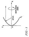
- Figure 1 depicts an ordinary parabolic reflector.
- Figure 2 is an illustration of the new Orthogonal Parabolic Reflector.
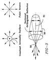
- Figure 3 illustrates the properties of the Orthogonal Parabolic Reflector which can create a substantially dimensionless point source.
- Figure 4 is an illustration of the compound system utilizing the Orthogonal Parabolic Reflector and an ordinary optical lens system.
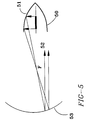
- Figure 5 is another example of a compound orthogonal reflector with an ordinary parabolic reflector.
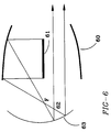
- Figure 6 illustrates another Orthogonal Parabolic Reflector compounded with a regular parabolic reflector.
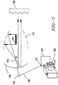
- Figure 7 illustrates a focused and zoom xenon lamp with camera.
- Figure 8 illustrates the electrically driven compound system with an air pusher through a nozzle in conjunction with light.
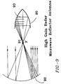
- Figure 9 illustrates the application of a compound orthogonal reflector and ordinary reflectors as a high gain antenna for the purpose of detecting coherent or coincident signals from far away.
- Figure 10 illustrates the complete Orthogonal parabolic Reflector which consists of two linear radiation sources.
- Figure 1 describes an ordinary parabolic reflector.
- the focal point (P,0) depicted here is where a point source normally will be located such that the point source will be reflected by the parabolic reflector to become a parallel beam.
- the parabolic reflector is a receiver, then in the parallel direction of the parabolic mirror axis, the signal will be focused onto the focal point (P,0) where a detector will be located. Moving away from the focal point will focus the beam at a distance or diffuse the beam with a given angle.
- the near linear source as depicted here from S 1 to S 3 will all be reflected at the focal point at the position (P,0), and the linear source from S 1 to S 3 is on the axis of the Orthogonal Parabolic Reflector; therefore, the intensity at the focal point is a sum of the linear source limited by the same material properties.
- the result is that the intensity can be multiplied by integrating the total energy source from S 1 to S 3 , and the energy will arrive at the focal point (P,0) and will be intensified by orders of magnitude of a point source with the same material limitations.
- the distance anywhere within the linear source S 1 to S 3 to the focal point are equal; therefore, if the source is a coherent light source, the point source at the focal point also will be coherent.
- Figure 3 illustrates the dimensionless point source capability of the Orthogonal Parabolic Reflector.
- the top part of Figure 3 illustrates a dimensionless line source would have the same property as a cylindrical surface radiating at a constant intensity.
- the cylindrical surface is described by the constant intensity flux surface.
- This is the principle of source and sink, that there is a number of concentric rings about the point/linear source having the same total flux.
- the flux density times the surface area of these concentric circles is a constant, which is the same as a linear source which does not have a physical dimension.
- the radiation from a cylindrical surface appears to be emitted in the center of the cylinder without a physical dimension. If we can focus this linear source onto a point, then the radiation at that point is dimensionless.
- Orthogonal Parabolic Reflector illustrates the position of the orthogonal reflector, which is truncated by the necessary sections only.
- 31 illustrates the position of the line source or sink.
- 32 is the resultant focal point which concentrates the energy emitted from the line or cylindrical radiation source onto the focal point 32 .
- the radiation appears to have no apparent dimensions, and the equal distance from the focal point reflected to the axis is unique of the Orthogonal Parabolic mirrors. If the light source emits a coherent radiation, then at the focal point in all angles, the light also will be emitting as a coherent point source.
- the focal point 32 Due to the fact there is no material present at the focal point 32 , there is no material limitation in terms of the physical size and energy density or flux densities. Due to the apparent dimensionless property, the spatial filter located at that focal point will not reduce the intensity of the radiation source. This is another one of the breakthroughs of using Orthogonal Parabolic Reflectors in addition to the capability of increased intensity. This property will enable the light to be emitted with excellent beam quality.
- Figure 4 illustrates that one can use an Orthogonal Parabolic Reflector in an optical application such that the reflector is depicted again by 40 and the light source 41 and the focal point 42 .
- an optical lens 43 which would have the same focal point at 42 depicted by the letter F , then this lens will convert a linearly produced radiation source into a parallel beam.
- a parallel beam can be applied to many uses; typically, optical interferrometers, projector systems, shadowgraphs, lithographs, photographs, calibration, and in many other radiation applications, including sound system designing, etc.
- the applications require the resolution to be high and is limited by the dimension of the point source and the light intensity, with the new point source having no dimension. Then the resolution will be enhanced by orders of magnitude. This is only possible by using the Orthogonal Parabolic Reflectors.
- Figure 5 depicts yet another application such as a microwave or radar antenna, where an Orthogonal Parabolic Reflector is used in conjunction with a regular parabolic reflector.
- the parabolic reflector will share the same focal distance of focal point F with the Orthogonal Parabolic Reflectors.
- the Orthogonal Parabolic Reflector is depicted by 50 ; a linear source or detector array is depicted by 51 ; the focal point, 52 ; the parabolic reflector, 53 .
- the combination of these two reflectors gives either increased intensity of the radiation due to its inherent radiating power, or increased gain property of detection due to the coherent receiving ability of distant signals. Perturbing the focal points of the two will also focus the beam or diverge the beam with a given angle.
- Figure 6 illustrates another use of a compound Orthogonal Parabolic Reflector with an ordinary parabolic reflector sharing the same focal point F at 62 .
- the linear source in this case could be a xenon lamp oriented in the actual direction of the ordinary parabolic reflectors.
- 60 reflects a section of the Orthogonal Parabolic Reflector.
- the linear radiation source 61 reflects from the Orthogonal Parabolic Reflector and is focused at the same focal point as the parabolic reflector 63 , which creates an intense parallel beam.
- the reflector has a very short focal distance; therefore, the intense beam will have a diameter smaller than the sectional opening of the Orthogonal Parabolic Reflectors.
- Such an application is good for a focused xenon flash lamp such that the light will be more focused in the direction of the reflector.
- FIG. 7 A simplified illustration of using this combination in conjunction with a zoom camera is depicted in Figure 7.
- the automatic zoom camera or zoom camera will focus its image by zooming the image into the focal plane of the camera using the movement of a telescopic lens.
- the movement of the lens can go through a series of mechanical levers to also move the ordinary parabolic reflector slightly in order to focus the beam at a certain given distance.
- 71 is the Orthogonal Parabolic Reflector
- 72 is the linear light source of a xenon lamp or an intense tungsten filament.
- 73 is the focal point common to both reflectors.
- 74 is the ordinary reflector; 75 is the hinge linking the Parabolic Reflector to a lever with a hinge point at 76 , and the lever 77 will link to a position anchored to the camera zoom lens, 70 .
- the zoom lens is being depicted by 79 . Therefore, the focal point of the spread of the light will coincide with the zoom lens images.
- Other accessories can be added to the front such as a washer plate diffuser, depicted as 78 . Many other additions can be thought of as an add-on to the automatic zoom flash lamp system, or just a zoom lamp system, depending on the light source.
- Figure 8 describes yet another compound ordinary parabolic reflector with Orthogonal Parabolic Reflectors with a linear source.
- the parabolic reflectors were energized by the electromagnetic transducer such as a speaker voice coil 84 . If the case is part of a small speaker system, then the reflection will focus the beam along the axis of the light source 83 .
- the Orthogonal Parabolic Reflector is depicted by 82 .
- the source is depicted as 83 ; the focal point, 81 ; a speaker of pusher type, 88 , with a check valve to induce air into the system.
- 86 is the supporting frame. If the flash lamp is fired, yet the reflector is also being moved by another means, then the light can be shined on the target as first focused, then gradually unfocused. If the movement is energetic enough to push air, the air can be converged through another attachment nozzle 87 to become a high-speed ejector of a smoke ring with sound, and the smoke can be generated by other means, such as a smoke ring generator, depicted by 89 . A combination of this can be made into an imaginative toy which has magical visuals and sensational effects.
- the device can be used to demonstrate the different speeds of propagating methods.
- Figure 9 illustrates the use of the Orthogonal Parabolic Reflector 90 and the parabolic receiving reflector 92 , which will focus the signal through 91 and reflect the signal on a detector, 93 .
- the microwave signal detection from distant stars due to its linear array of detectors can be viewed as coincidental detectors; therefore, using the phase locked signal detection and discrimination, which would synchronize the signal in a spatial sense through identifying the real signal with a certain spatial resolution, rejecting the random noise from the air current and other reasons. This eliminates multiple antenna array currently being used.
- Figure 10 is the illustration of a complete orthogonal reflector.
- the shape will be like an American football.
- the two linear sources placed on the axis if were very powerful radiation sources, can be focused onto a point of almost no dimension, and such an intense source can be used as a calibration standard or can be used for laser fusion and in many other applications for dimensionless point source with extremely high intensity. On the other hand, it also can be used as sensitive detector to discriminate signals against noise.
- the geometry is given a name as Orthogonal Parabolic Reflector (OPR), or simply Cheng Reflector.
- OCR Orthogonal Parabolic Reflector
- the object of the reflector is to transform a linear source or sink (detector) onto a single focal point, where the resultant radiation at the focal point will theoretically not have a physical dimension, and if the point is surrounded by a vacuum vessel, there will not be a power or intensity limitation as well.
- OCR Orthogonal Parabolic Reflector
- the description above contains many specificities; however, they should not be construed as the limit of the scope of the invention, but as merely providing illustrations of some of the presently preferred embodiments of this invention.
- the improvement in material for the construction of the reflector surface can contain selectively properties of wave length or frequencies so that the system will only reflect according to OPR principle within those wave lengths and frequencies.
- the perturbation away from the perfect position sometimes is also desirable for special applications. The deviation will be considered obvious by those possessed of the appropriate skills.
Landscapes
- Physics & Mathematics (AREA)
- Engineering & Computer Science (AREA)
- General Engineering & Computer Science (AREA)
- General Physics & Mathematics (AREA)
- Optics & Photonics (AREA)
- Aerials With Secondary Devices (AREA)
- Optical Elements Other Than Lenses (AREA)
- Variable-Direction Aerials And Aerial Arrays (AREA)
Claims (19)
- Reflektorsystem miteinem Reflektor (30; 40; 50; 60; 71; 82; 90), der eine reflektierende Oberfläche aufweist, die annähernd einer Oberfläche, die durch Drehen eines Abschnitts einer parabolischen Kurve um eine senkrecht zur Achse der Parabel und durch den Brennpunkt der Parabel (32; 42; 73; 81; 91) laufenden Achse erzeugt wird, entspricht; undeiner gestreckten Quelle oder Senke (31; 41; 51; 61; 72; 83; 93), die wenigstens teilweise von dem Reflektor (30; 40; 50; 60; 71; 82; 90) eingehüllt wird,dadurch gekennzeichnet, daß die gestreckte Quelle oder Senke (31; 41; 51; 61; 72; 83; 93) sich in etwa längs der Drehachse des Reflektors (30; 40; 50; 60; 71; 82; 90) erstreckt, weswegen der Reflektor die gestreckte Quelle oder Senke (31; 41; 51; 61; 72; 83; 93) in eine Punktquelle oder -Senke (32; F; 42; 73; 81; 91) umwandelt.
- Reflektorsystem gemäß Anspruch 1, bei dem die reflektierende Oberfläche auf einer Seite längs der Drehachse offen ist, um Strahlung aufzunehmen oder auszusenden, und auf der anderen Seite längs der Drehachse im wesentlichen geschlossen ist.
- Reflektorsystem gemäß Anspruch 1, bei dem die reflektierende Oberfläche auf beiden Seiten längs der Drehachse offen ist, um Strahlung wenigstens durch eine der offenen Seiten aufzunehmen oder auszusenden.
- Reflektorsystem gemäß Anspruch 1 oder 2 oder 3, das weiter eine Linse (43) mit einem auch im wesentlichen an der Drehachse befindlichen Brennpunkt (F) aufweist.
- Reflektorsystem gemäß Anspruch 4, bei dem die Brennpunkte der reflektierenden Oberfläche und der Linse (43) im wesentlichen zusammenfallen.
- Reflektorsystem gemäß Anspruch 4, bei dem die Brennpunkte der reflektierenden Oberfläche und der Linse (43) relativ über einen Bereich von Positionen, die eine Position, bei der die beiden Brennpunkte im wesentlichen zusammenfallen, enthält, bewegbar sind.
- Reflektorsystem gemäß Anspruch 1, bei dem die reflektierende Oberfläche aus einer ersten reflektierenden Oberfläche (50) mit einem ersten, im wesentlichen an der Drehachse liegenden Brennpunkt besteht, und das eine zweite parabolische, reflektierende Oberfläche (53), die der ersten Oberfläche gegenüberliegt und einen zweiten Brennpunkt, der sich in einem bestimmten räumlichen Verhältnis relativ zum ersten Brennpunkt befindet, aufweist.
- Reflektorsystem gemäß Anspruch 7, bei dem die ersten und zweiten Brennpunkte relativ über einen Bereich von Positionen, die ein im wesentlichen Zusammenfallen beider beinhaltet, bewegbar sind.
- Reflektorsystem gemäß Anspruch 1, bei dem die reflektierende Oberfläche aus einer ersten reflektierenden Oberfläche (60) mit einem ersten Brennpunkt, der im wesentlichen an der Drehachse liegt, besteht, und das eine zweite parabolische, reflektierende Oberfläche (63), die der ersten Oberfläche gegenüberliegt und einen zweiten Brennpunkt hat, der ein bestimmtes räumliches Verhältnis relativ zum ersten Brennpunkt hat, aufweist, wobei die erste reflektierende Oberfläche auf beiden Seiten längs der Drehachse offen ist, um Strahlung über beide offenen Seiten aufzunehmen/auszusenden.
- Reflektorsystem gemäß Anspruch 9, bei dem die ersten und zweiten Brennpunkte relativ über einen Bereich von relativen Positionen, die eine Position, bei der die Brennpunkte im wesentlichen zusammenfallen, enthält, bewegbar sind.
- Reflektorsystem gemäß Anspruch 9, bei dem die ersten und zweiten Brennpunkte im wesentlichen zusammenfallen.
- Reflektorsystem gemäß Anspruch 1, bei dem die reflektierende Oberfläche aus einer ersten reflektierenden Oberfläche (71) mit einem ersten Brennpunkt (73) besteht, und das System weiter (i) eine zweite reflektierende Oberfläche (74) mit einem zweiten Brennpunkt (F), der ein bestimmtes räumliches Verhältnis relativ zum ersten Brennpunkt hat; (ii) eine Kamera mit einer Zoomlinse (79), die mit relativ zueinander beweglichen optischen Elementen versehen ist; und (iii) einen Mechanismus (75 bis 77), der die Zoomlinse und wenigstens eine der ersten und zweiten reflektierenden Oberflächen verbindet, um das räumliche Verhältnis zwischen den Brennpunkten zu ändern, aufweist.
- Reflektorsystem gemäß Anspruch 12, weiter enthaltend eine Lichtquelle (72), die mit wenigstens einer der reflektierenden Oberflächen zusammenwirkt, um einen ersten Lichtstrahl zu bilden, der auf die andere reflektierende Oberfläche trifft, wobei der Mechanismus (75 bis 77) das räumliche Verhältnis der zwei Brennpunkte ändert, um den Grad von Konvergenz oder Divergenz des Lichtstrahls, die durch seine Reflexion an der anderen Oberfläche bewirkt werden, zu verändern, weswegen der Lichtstrahl in einer Weise fokussierbar ist, die im Bezug zum Fokussieren der Zoomlinse steht.
- Reflektorsystem gemäß einem der Ansprüche 1 bis 10, bei dem die gestreckte Quelle oder Senke einen gestreckten Detektor (93) für Strahlung, die auf den Detektor durch die reflektierende Oberfläche reflektiert wird, aufweist.
- Reflektorsystem gemäß Anspruch 14, bei dem der Detektor ein Mikrowellendetektor (93) ist.
- Reflektorsystem gemäß Anspruch 14, bei dem der Detektor ein lineares Array von Detektorelementen, die sich längs der Drehachse erstrecken, aufweist.
- Reflektorsystem gemäß Anspruch 1, bei dem die reflektierende Oberfläche eine im wesentlichen geschlossen dimensionierte Oberfläche aufweist.
- Reflektorsystem gemäß Anspruch 17, bei dem die gestreckte Quelle oder Senke wenigstens eine gestreckte Quelle oder Senke, die sich annähernd längs eines Teils der Drehachse erstreckt, den die reflektierende Oberfläche einschließt, und eine Punktquelle oder -Senke im Zentrum der dreidimensionalen reflektierenden Oberfläche aufweist.
- Reflektorsystem gemäß einem der vorhergehenden Ansprüche, wobei der Reflektor so angeordnet ist, daß er die gestreckte Quelle oder Senke in eine gestörte Punktquelle oder -Senke umwandelt.
Applications Claiming Priority (3)
| Application Number | Priority Date | Filing Date | Title |
|---|---|---|---|
| US07/455,518 US5037191A (en) | 1989-12-21 | 1989-12-21 | Orthogonal parabolic reflector systems |
| US455518 | 1989-12-21 | ||
| PCT/US1990/007575 WO1991010212A1 (en) | 1989-12-21 | 1990-12-20 | Orthogonal parabolic reflector systems |
Publications (3)
| Publication Number | Publication Date |
|---|---|
| EP0506882A1 EP0506882A1 (de) | 1992-10-07 |
| EP0506882A4 EP0506882A4 (en) | 1992-12-23 |
| EP0506882B1 true EP0506882B1 (de) | 1996-08-28 |
Family
ID=23809137
Family Applications (1)
| Application Number | Title | Priority Date | Filing Date |
|---|---|---|---|
| EP91903020A Expired - Lifetime EP0506882B1 (de) | 1989-12-21 | 1990-12-20 | Rechtwinkelige parabolische reflektorsysteme |
Country Status (9)
| Country | Link |
|---|---|
| US (1) | US5037191A (de) |
| EP (1) | EP0506882B1 (de) |
| JP (1) | JP3220452B2 (de) |
| AT (1) | ATE142026T1 (de) |
| AU (1) | AU7182691A (de) |
| CA (1) | CA2071635C (de) |
| DE (1) | DE69028316T2 (de) |
| TW (1) | TW219977B (de) |
| WO (1) | WO1991010212A1 (de) |
Families Citing this family (22)
| Publication number | Priority date | Publication date | Assignee | Title |
|---|---|---|---|---|
| US5235470A (en) * | 1989-12-21 | 1993-08-10 | Cheng Dah Y | Orthogonal parabolic reflector systems |
| RU2047876C1 (ru) * | 1993-03-30 | 1995-11-10 | Научно-производственная фирма "МГМ" | Устройство для светолучевой обработки |
| GB9506010D0 (en) * | 1995-03-23 | 1995-08-23 | Anderson John E | Electromagnetic energy directing method and apparatus |
| GB2305516B (en) * | 1995-03-23 | 1999-04-07 | John Ernest Anderson | Directing electromagnetic energy from an area or volume source |
| US5650869A (en) * | 1995-05-05 | 1997-07-22 | The United States Of America As Represented By The Administrator Of The National Aeronautics And Space Administration | Point relay scanner utilizing ellipsoidal mirrors |
| US5757557A (en) * | 1997-06-09 | 1998-05-26 | Tir Technologies, Inc. | Beam-forming lens with internal cavity that prevents front losses |
| US6176597B1 (en) | 1998-03-27 | 2001-01-23 | Hill-Rom, Inc. | Reflector for surgical light apparatus |
| US7336403B2 (en) * | 2002-05-27 | 2008-02-26 | Canon Kabushiki Kaisha | Optical element and illumination apparatus having same |
| US6705737B1 (en) * | 2002-08-20 | 2004-03-16 | Raytheon Co. | Reflective optical apparatus for interconverting between a point of light and a line of light |
| KR20040028143A (ko) * | 2002-09-30 | 2004-04-03 | 유상일 | 공간결상 광학장치 |
| US7110107B2 (en) * | 2002-12-20 | 2006-09-19 | Corning Incorporated | Capillary assay device and method |
| US7034320B2 (en) * | 2003-03-20 | 2006-04-25 | Intel Corporation | Dual hemispherical collectors |
| US20070211471A1 (en) * | 2003-10-27 | 2007-09-13 | Wimberly Randal L | Dual Reflector System |
| US20070205724A1 (en) * | 2006-03-03 | 2007-09-06 | Schaefer Raymond B | Advanced surface discharge lamp systems |
| US7593289B2 (en) * | 2006-04-17 | 2009-09-22 | Phoenix Science & Technology, Inc. | Reflectors and reflector light and sound source systems |
| DE102009013812A1 (de) | 2009-03-18 | 2010-09-23 | Osram Gesellschaft mit beschränkter Haftung | Reflektor, Lichtquellenanordnung sowie Projektorgerät |
| US9115867B2 (en) * | 2010-10-19 | 2015-08-25 | Macdonald, Dettwiler And Associates Inc. | Dual reflector system for linear lamp illuminators |
| US9360680B1 (en) | 2012-08-10 | 2016-06-07 | Ilias Syrgabaev | Electromagnetic beam or image stabilization system |
| NZ785411A (en) * | 2016-02-26 | 2024-02-23 | Magic Leap Inc | Light output system with reflector and lens for highly spatially uniform light output |
| CN109244678B (zh) * | 2018-09-27 | 2023-10-17 | 中国科学院国家天文台 | 一种索系基础望远镜反射面结构 |
| JP7244284B2 (ja) * | 2019-01-25 | 2023-03-22 | フタバ産業株式会社 | 消音器及び排気管 |
| CN112394501B (zh) * | 2020-11-04 | 2022-05-10 | 北京遥测技术研究所 | 一种星载柔性射频激光一体化通信天线 |
Family Cites Families (7)
| Publication number | Priority date | Publication date | Assignee | Title |
|---|---|---|---|---|
| US2252246A (en) * | 1941-08-12 | Optical system | ||
| US2759106A (en) * | 1951-05-25 | 1956-08-14 | Wolter Hans | Optical image-forming mirror system providing for grazing incidence of rays |
| US3532417A (en) * | 1967-07-20 | 1970-10-06 | Gen Electric | Noninverting optical reflecting device |
| US4484334A (en) * | 1981-11-17 | 1984-11-20 | Allied Corporation | Optical beam concentrator |
| DE3340462C1 (de) * | 1983-11-09 | 1985-04-18 | Westfälische Metall Industrie KG Hueck & Co, 4780 Lippstadt | Abgeblendeter Fahrzeugscheinwerfer |
| US4557569A (en) * | 1983-11-17 | 1985-12-10 | The United States Of America As Represented By The Secretary Of The Army | Distended point source reflector having conical sections |
| US4886348A (en) * | 1988-10-26 | 1989-12-12 | Westinghouse Electric Corp. | Total transmissibility optical system |
-
1989
- 1989-12-21 US US07/455,518 patent/US5037191A/en not_active Expired - Fee Related
-
1990
- 1990-12-20 WO PCT/US1990/007575 patent/WO1991010212A1/en active IP Right Grant
- 1990-12-20 DE DE69028316T patent/DE69028316T2/de not_active Expired - Fee Related
- 1990-12-20 JP JP50329791A patent/JP3220452B2/ja not_active Expired - Fee Related
- 1990-12-20 AU AU71826/91A patent/AU7182691A/en not_active Abandoned
- 1990-12-20 EP EP91903020A patent/EP0506882B1/de not_active Expired - Lifetime
- 1990-12-20 CA CA002071635A patent/CA2071635C/en not_active Expired - Fee Related
- 1990-12-20 AT AT91903020T patent/ATE142026T1/de not_active IP Right Cessation
-
1991
- 1991-02-13 TW TW080101209A patent/TW219977B/zh active
Also Published As
| Publication number | Publication date |
|---|---|
| DE69028316D1 (de) | 1996-10-02 |
| JP3220452B2 (ja) | 2001-10-22 |
| AU7182691A (en) | 1991-07-24 |
| JPH05505683A (ja) | 1993-08-19 |
| ATE142026T1 (de) | 1996-09-15 |
| EP0506882A1 (de) | 1992-10-07 |
| DE69028316T2 (de) | 1997-03-06 |
| EP0506882A4 (en) | 1992-12-23 |
| CA2071635A1 (en) | 1991-06-22 |
| WO1991010212A1 (en) | 1991-07-11 |
| CA2071635C (en) | 2001-09-11 |
| US5037191A (en) | 1991-08-06 |
| TW219977B (de) | 1994-02-01 |
Similar Documents
| Publication | Publication Date | Title |
|---|---|---|
| EP0506882B1 (de) | Rechtwinkelige parabolische reflektorsysteme | |
| US4755918A (en) | Reflector system | |
| JP4792486B2 (ja) | フレネルレンズライト用、特にスポットライトあるいはフラッドライト用光学系 | |
| KR0125493B1 (ko) | 반사성 필름 | |
| US3827059A (en) | Catoptric lens arrangement | |
| CA2402560C (en) | Coupling of light from a light source to a target using dual ellipsoidal reflectors | |
| US4357075A (en) | Confocal reflector system | |
| US4809147A (en) | Lighting device | |
| JP2009122686A (ja) | 光学装置 | |
| TWI232351B (en) | Dual hemispherical collectors | |
| US3494693A (en) | Radiant energy projection | |
| KR20030068132A (ko) | 렌즈가 갖춰진 광 파이프를 사용하는 광 집속 및 수집시스템 | |
| US5235499A (en) | Lamp system having a torroidal light emitting member | |
| US4050775A (en) | Catoptric lens arrangement | |
| US4783725A (en) | Flashlight with space efficient reflector | |
| US3900726A (en) | Compact follow spot | |
| JPH02148602A (ja) | 自動車用前照灯 | |
| US3892476A (en) | Catoptric system for simultaneous concentration of light, laser, and other type paraxial rays into beams | |
| US5143447A (en) | Lamp system having a torroidal light emitting member | |
| JP2003124741A (ja) | 可変焦点距離電磁波集束装置 | |
| JP2003527752A (ja) | 超高分解能イメージング・デバイス | |
| JPS59143117A (ja) | 集光器 | |
| JP2940132B2 (ja) | 放光装置 | |
| CA2608368A1 (en) | Dual paraboloid reflector and dual ellipsoid reflector systems with optimized magnification | |
| JP3415879B2 (ja) | 照射装置 |
Legal Events
| Date | Code | Title | Description |
|---|---|---|---|
| PUAI | Public reference made under article 153(3) epc to a published international application that has entered the european phase |
Free format text: ORIGINAL CODE: 0009012 |
|
| 17P | Request for examination filed |
Effective date: 19920721 |
|
| AK | Designated contracting states |
Kind code of ref document: A1 Designated state(s): AT BE CH DE DK ES FR GB GR IT LI LU NL SE |
|
| A4 | Supplementary search report drawn up and despatched |
Effective date: 19921103 |
|
| AK | Designated contracting states |
Kind code of ref document: A4 Designated state(s): AT BE CH DE DK ES FR GB GR IT LI LU NL SE |
|
| 17Q | First examination report despatched |
Effective date: 19940818 |
|
| GRAH | Despatch of communication of intention to grant a patent |
Free format text: ORIGINAL CODE: EPIDOS IGRA |
|
| GRAH | Despatch of communication of intention to grant a patent |
Free format text: ORIGINAL CODE: EPIDOS IGRA |
|
| GRAA | (expected) grant |
Free format text: ORIGINAL CODE: 0009210 |
|
| AK | Designated contracting states |
Kind code of ref document: B1 Designated state(s): AT BE CH DE DK ES FR GB GR IT LI LU NL SE |
|
| PG25 | Lapsed in a contracting state [announced via postgrant information from national office to epo] |
Ref country code: CH Effective date: 19960828 Ref country code: IT Free format text: LAPSE BECAUSE OF FAILURE TO SUBMIT A TRANSLATION OF THE DESCRIPTION OR TO PAY THE FEE WITHIN THE PRE;WARNING: LAPSES OF ITALIAN PATENTS WITH EFFECTIVE DATE BEFORE 2007 MAY HAVE OCCURRED AT ANY TIME BEFORE 2007. THE CORRECT EFFECTIVE DATE MAY BE DIFFERENT FROM THE ONE RECORDED.SCRIBED TIME-LIMIT Effective date: 19960828 Ref country code: GR Free format text: LAPSE BECAUSE OF FAILURE TO SUBMIT A TRANSLATION OF THE DESCRIPTION OR TO PAY THE FEE WITHIN THE PRESCRIBED TIME-LIMIT Effective date: 19960828 Ref country code: BE Effective date: 19960828 Ref country code: LI Effective date: 19960828 Ref country code: AT Effective date: 19960828 Ref country code: ES Free format text: THE PATENT HAS BEEN ANNULLED BY A DECISION OF A NATIONAL AUTHORITY Effective date: 19960828 Ref country code: FR Effective date: 19960828 Ref country code: DK Effective date: 19960828 |
|
| REF | Corresponds to: |
Ref document number: 142026 Country of ref document: AT Date of ref document: 19960915 Kind code of ref document: T |
|
| REF | Corresponds to: |
Ref document number: 69028316 Country of ref document: DE Date of ref document: 19961002 |
|
| PG25 | Lapsed in a contracting state [announced via postgrant information from national office to epo] |
Ref country code: SE Effective date: 19961128 |
|
| PG25 | Lapsed in a contracting state [announced via postgrant information from national office to epo] |
Ref country code: LU Free format text: LAPSE BECAUSE OF NON-PAYMENT OF DUE FEES Effective date: 19961231 |
|
| EN | Fr: translation not filed | ||
| REG | Reference to a national code |
Ref country code: CH Ref legal event code: PL |
|
| PLBE | No opposition filed within time limit |
Free format text: ORIGINAL CODE: 0009261 |
|
| STAA | Information on the status of an ep patent application or granted ep patent |
Free format text: STATUS: NO OPPOSITION FILED WITHIN TIME LIMIT |
|
| 26N | No opposition filed | ||
| REG | Reference to a national code |
Ref country code: GB Ref legal event code: IF02 |
|
| PGFP | Annual fee paid to national office [announced via postgrant information from national office to epo] |
Ref country code: GB Payment date: 20021218 Year of fee payment: 13 |
|
| PGFP | Annual fee paid to national office [announced via postgrant information from national office to epo] |
Ref country code: NL Payment date: 20021227 Year of fee payment: 13 |
|
| PGFP | Annual fee paid to national office [announced via postgrant information from national office to epo] |
Ref country code: DE Payment date: 20021231 Year of fee payment: 13 |
|
| PG25 | Lapsed in a contracting state [announced via postgrant information from national office to epo] |
Ref country code: GB Free format text: LAPSE BECAUSE OF NON-PAYMENT OF DUE FEES Effective date: 20031220 |
|
| PG25 | Lapsed in a contracting state [announced via postgrant information from national office to epo] |
Ref country code: DE Free format text: LAPSE BECAUSE OF NON-PAYMENT OF DUE FEES Effective date: 20040701 Ref country code: NL Free format text: LAPSE BECAUSE OF NON-PAYMENT OF DUE FEES Effective date: 20040701 |
|
| GBPC | Gb: european patent ceased through non-payment of renewal fee |
Effective date: 20031220 |
|
| NLV4 | Nl: lapsed or anulled due to non-payment of the annual fee |
Effective date: 20040701 |