EP0506005A2 - Vorrichtung zur Messung der Abmessung eines eines Körpers - Google Patents
Vorrichtung zur Messung der Abmessung eines eines Körpers Download PDFInfo
- Publication number
- EP0506005A2 EP0506005A2 EP92105114A EP92105114A EP0506005A2 EP 0506005 A2 EP0506005 A2 EP 0506005A2 EP 92105114 A EP92105114 A EP 92105114A EP 92105114 A EP92105114 A EP 92105114A EP 0506005 A2 EP0506005 A2 EP 0506005A2
- Authority
- EP
- European Patent Office
- Prior art keywords
- probe
- frame
- work
- impedance
- subprobe
- Prior art date
- Legal status (The legal status is an assumption and is not a legal conclusion. Google has not performed a legal analysis and makes no representation as to the accuracy of the status listed.)
- Granted
Links
Images




Classifications
-
- G—PHYSICS
- G01—MEASURING; TESTING
- G01B—MEASURING LENGTH, THICKNESS OR SIMILAR LINEAR DIMENSIONS; MEASURING ANGLES; MEASURING AREAS; MEASURING IRREGULARITIES OF SURFACES OR CONTOURS
- G01B7/00—Measuring arrangements characterised by the use of electric or magnetic techniques
- G01B7/16—Measuring arrangements characterised by the use of electric or magnetic techniques for measuring the deformation in a solid, e.g. by resistance strain gauge
-
- G—PHYSICS
- G01—MEASURING; TESTING
- G01B—MEASURING LENGTH, THICKNESS OR SIMILAR LINEAR DIMENSIONS; MEASURING ANGLES; MEASURING AREAS; MEASURING IRREGULARITIES OF SURFACES OR CONTOURS
- G01B5/00—Measuring arrangements characterised by the use of mechanical techniques
- G01B5/02—Measuring arrangements characterised by the use of mechanical techniques for measuring length, width or thickness
-
- G—PHYSICS
- G01—MEASURING; TESTING
- G01D—MEASURING NOT SPECIALLY ADAPTED FOR A SPECIFIC VARIABLE; ARRANGEMENTS FOR MEASURING TWO OR MORE VARIABLES NOT COVERED IN A SINGLE OTHER SUBCLASS; TARIFF METERING APPARATUS; MEASURING OR TESTING NOT OTHERWISE PROVIDED FOR
- G01D21/00—Measuring or testing not otherwise provided for
- G01D21/02—Measuring two or more variables by means not covered by a single other subclass
-
- G—PHYSICS
- G01—MEASURING; TESTING
- G01G—WEIGHING
- G01G19/00—Weighing apparatus or methods adapted for special purposes not provided for in the preceding groups
- G01G19/14—Weighing apparatus or methods adapted for special purposes not provided for in the preceding groups for weighing suspended loads
- G01G19/18—Weighing apparatus or methods adapted for special purposes not provided for in the preceding groups for weighing suspended loads having electrical weight-sensitive devices
-
- G—PHYSICS
- G01—MEASURING; TESTING
- G01G—WEIGHING
- G01G19/00—Weighing apparatus or methods adapted for special purposes not provided for in the preceding groups
- G01G19/52—Weighing apparatus combined with other objects, e.g. furniture
Definitions
- This invention relates generally to a device for measuring the physical state of a work which is subjected to a high temperature atmosphere. More specifically, this invention relates to a device for measuring a change in the physical state of a work which is placed in a high temperature furnace by measuring the weight and dimension of the work.
- a typical work to be processed in the furnace is a body formed by powder metals or ceramics.
- the molded body or sample is made of a raw material mixed with wax and formed into a desired shape.
- the molded body is first dewaxed in the furnace and then subjected to a sintering process.
- Dewaxing is a process in which the molded body is heated in the furnace thereby to remove the wax contained in the molded body. If, in the course of the process, the temperature and pressure within the furnace are not controlled properly, the wax within the molded body vaporizes too quickly, or sintering proceeds at an unusually fast rate. This causes undesired cracks in and disfigurement of the molded body.
- the weight of a sample body is determined by supporting it by the weight measuring mechanism, or else the vertical dimension of the sample body is measured by detecting by a sensing rod the distance between a position of the upper surface of the sample body and a position of a base on which the sample body is placed.
- the prior art arrangement is disadvantageous in that two separate measuring mechanisms must be provided at different locations, making the entire structure bulky and complex.
- the weight and dimension measurement with the conventional arrangement is quite prone to error since the device has a pressure difference in the furnace, in order to prevent wax from staining the heat insulating material. This pressure difference causes error in weight measurement by changing the force on the supporting element of the work. Also, it causes error in dimension measurement by changing the contact force of the sensing rod which is placed on the work.
- This invention has been made with the above-mentioned problems in mind, and its purpose is to provide a device for measuring the physical state of an object which can solve the problems.
- a device for measuring the physical state of an object under high temperature conditions which comprises: a frame for holding an object; a base on which the frame is placed; a probe having an end portion disposed for relative movement between the object and the frame and for lifting the frame together with the object away from the base; displacement detecting means for detecting a displacement of the probe, and load detecting means for detecting a load imposed on the probe.
- the device of the invention is characterized in that the vertical dimension of the object is obtained from the amount of relative displacement of the probe detected by the displacement detecting means, and the weight of the object is obtained from the load difference detected by the weight detecting means.
- a compensator may be added.
- the vertical dimension of the compensator and the vertical dimension of the support frame are determined in relation to their coefficients of linear expansion, so that the maximum allowable displacement of the probe in its longitudinal direction is substantially kept constant without being affected by the thermal distortion of the frame caused by changes in the ambient temperature.
- the probe may be so designed as to be able to measure a very fragile object.
- the end portion of the probe is modified into a subprobe and its holder.
- the subprobe is lifted after it makes contact with the object, so that the contact force on the object is restricted within the weight of the subprobe.
- the object that is supported by the probe may be oscillated by a drive mechanism for moving the probe vertically up and down.
- the waveform of the oscillation that appears in the output from the load detecting means may be electrically processed, and the mass of the object is obtained from the well-known equations of the oscillating system.
- the impedance of an object helps to determine such physical properties of the object as carbon content.
- the impedance of the object may be obtained from the impedance between the probe and that of the base when the probe is in contact with the object, the impedance therebetween when the probe is in contact with the support frame without lifting it, and the impedance of the support frame itself.
- the device of the invention is so designed as to measure cyclically or intermittently changes in the weight and dimension of an object by moving a probe upward and downward.
- the object being measured changes very slowly as compared with the measuring procedure, so that the intermittent steps of measurement may be regarded as being done simultaneously.
- the single integrated probe is simple in construction and the device gets a less adverse effect of the temperature in the furnace.
- the vertical dimension of the object is determined by the amount of displacement of the end portion of the probe between the object and the frame, and the displacement of the probe corresponds accurately to the displacement of the end portion of the probe, measurement errors which would result from thermal expansion of the probe or the base are effectively canceled unless such expansion undergoes a great change in the course of a single measuring process.
- a very fragile object can be measured without being damaged by the probe.
- the equation used does not contain such items as the gas density and the gain of the load detecting means, so that an accurate measurement may be realized without being affected by a buoyant force applied on the object or by the gain drift of the detecting means.
- the arrangement of the invention that the probe is used as a contact point in an electric circuit for measuring the impedance of the object is effective in avoiding problems associated with the thermoelectrical properties of circuit elements. That is, the impedance between the impedance meter and the object can be eliminated.
- a measuring device according to one embodiment of the invention as incorporated in a sintering furnace.
- the furnace 1 includes a inner box 3, a heater 2a, a furnace chamber 1 and a heat-insulating material 2.
- a work A to be measured is housed within the inner box 3.
- the work A is held on the bottom surface 4a of a frame 4, which is in turn supported on a furnace bed 3a of the inner box 3 via a base 5.
- a probe 6 is suspended through the chamber 1, the heat-insulating material 2 and the inner box 3 to extend into the frame 4.
- the probe 6 is provided at its end with a diametrically enlarged portion 6a.
- the enlarged end portion 6a is held by the probe 6 for relative displacement between the top surface of the work A and the top wall 4b of the frame 4. As the probe 6 is pulled upward with the enlarged end member 6a abutting on the lower surface of the top wall 4b of the support frame 4, the support frame 4 is lifted upward together with the work A away from the base 5.
- the chamber 1 has a top-end opening 1a, to which a subchamber 7 is connected with seal elements 7a.
- a drive mechanism 8 supports the probe 6 which extends into the subchamber 7 for upward and downward movement.
- the drive mechanism 8 includes a load cell 8c to which the probe 6 is connected by a holder 8b via a leaf spring 8a; an arm 8d for supporting the fixed end of the load cell 8c; a rod 8e extending upward from the arm 8d out of the subchamber 7; a counter-spring 8h for biasing the rod 8e upward so that a cam follower 8f provided on the rod 8e comes into pressure contact with a cam 8g; a step motor 8i with gear reduction for driving the cam 8g and the mating cam follower 8f to move the rod 8e vertically upward or downward into a desired position; and a linear guide 8j for guiding the upward and downward motion of the rod 8e.
- the load imposed on the probe 6 is continuously taken out of the load cell 8c as an electrical signal.
- a magnetic scale 9 which is provided in contact with the rod 8e generates an electric signal indicative of the vertical displacement of the rod 8e, which corresponds to the vertical displacement of the end portion 6a of the probe 6.
- the step motor 8i, the magnetic scale 9 and the load cell 8c are connected to a microcomputer 10.
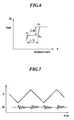
- the microcomputer 10 forms together with the magnetic scale 9 and the load cell 8c a displacement and load detecting mechanism, and detects changing relations as shown in Fig.6 between the displacement X of the rod 8e detected by the magnetic scale 9 and the load W detected by the load cell 8c.
- the microcomputer 10 determines from the changes of the detected values whether the enlarged end 6a of the probe is in contact with the work A (as shown at P1 in Fig. 6), or whether it is in contact with the under surface of the top wall 4b of the frame 4 (as shown at P2 in Fig. 6), or else whether it has pulled the frame 4 upward together with the work A (as shown at P3 in Fig. 6).
- the load imposed on the probe 6 when the enlarged end 6a of the probe 6 has pulled up the frame 4 is compared with the load imposed on the probe 6 when the end 6a does not pull up the frame to obtain a difference ⁇ W between the two loads.
- the weight W0 of the work A is then figured out by subtracting the weight of the frame 4 from the weight difference ⁇ W.
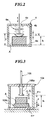
- the vertical dimension h of the work A is obtained first by determining a relative displacement ⁇ X of the rod 8e when the end 6a of the probe 6 moves from the work A to the lower surface of the top wall 4b of the frame 4 without lifting the frame 4, and then by subtracting the relative displacement ⁇ X from a maximum allowable displacement ⁇ of the end 6a of the probe (Fig. 2).
- the weight and dimension of the work are measured cyclically or intermittently by moving the probe 6 up and down. Since any change in the physical state of the work A such as an injection-molded body proceeds very slowly as compared with the intermittent measuring steps, the measuring steps can be regarded as having been taken simultaneously. As a consequence, it becomes possible to make an accurate measurement of both the weight and dimension of a work A by means of a single mechanism.
- the single integrated probe is simple in construction and the device gets a less adverse effect of the temperature in the furnace.
- the vertical dimension of the work A is obtained from the amount of relative displacement of the rod 8e which occurs when the end 6a of the probe 6 is allowed to move within the frame 4. Therefore, even if the probe 6 or base 5 expands due to thermal distortion, the relative displacement ⁇ X of the end 6a of the probe 6 corresponds accurately to the relative displacement of the rod 8e, so that measurement errors which would otherwise result from thermal expansion of the probe 6 or base 5 are effectively canceled unless a great expansion occurs in the course of a single measuring process.
- the probe 6 has a end portion 306 which has a generally U-shaped cross section, and the frame 304 is in the form of a plane member. As the probe 306 moves upward, it comes into engagement with the bottom surface of the frame 304 and lifts the frame together with the work A.
- a device contemplates to eliminate errors in the relative displacement of the probe that cannot effectively be canceled out by the preceding embodiment.
- the only error that can be canceled by the device of the first embodiment is the one which is caused outside the frame 4. Errors will be produced within the frame 4 as the vertical dimensions of the frame and the end 6a of the probe 6 change due to thermal expansion, causing a change in the maximum allowable displacement ⁇ of the probe. If the temperature of the frame is measured correctly, an electrical compensator may be possible. But it is usually difficult. Therefore, with the device of the second embodiment, as shown in Fig.
- a compensator 104c is placed between the frame 104 and the probe 106, and the vertical dimension l p of the compensator 104c and the vertical inner dimension l s of the frame 104 are determined to fulfill the following equation with respect to their coefficients ⁇ p and ⁇ s of linear expansion.
- ⁇ s ⁇ l s ⁇ p ⁇ l p
- the maximum allowable displacement ⁇ is kept approximately constant without being adversely affected by a change in the ambient temperature. As a result, any error within the frame 4 is eliminated, thereby improving measurement accuracy.
- a device is essentially the same as that of the first embodiment, but a modification is made to enable the measurement of a very fragile work A .
- the end 206a of the probe 206 is composed of a subprobe 216a and it's holder 216b.
- the subprobe 216a touches the work A , it is lifted from its holder 216b, so that the contact force on the work A is restricted with in the weight of the subprobe 216a.
- this arrangement it is possible to effectively measure the weight and dimension of a very fragile work A .
- a device is intended to obtain the mass of the work A from the oscillating waveform of the value detected by the load cell 8c by feeding it into a signal processing means such as the microcomputer 10 as described in connection with Fig. 1.
- a signal processing means such as the microcomputer 10 as described in connection with Fig. 1.
- the value W detected by the load cell 8c oscillates each time the displacement X of the rod 8e changes its direction as shown in Fig.7.
- the angular velocity ⁇ and the damping factor n of the oscillating system can be obtained from the waveform of the load W .
- the microcomputer processes the value detected by the load cell 8c.
- the angular velocity ⁇ is obtained from the cycle time of the waveform, and the damping factor n is obtained by the decaying ratio of the waveform.
- the value m includes the mass of the probe 6 in addition to the mass of the work A and the mass of the frame 4, and by subtracting the mass of the probe 6 and the frame from the value m , the mass of the work A is obtained.
- a device is essentially the same as that of the first embodiment, and so modified as to enable measurement of the impedance of the work A .
- an impedance meter 410 is connected between the end of the load cell 408c and a base 405 in the furnace.
- a reference numeral 410a indicates an electrically insulating material. The amount of impedance measured by the impedance meter 410 is supplied to a microcomputer 10.
- Fig. 9 illustrates an electrically equivalent circuit of this device.
- Z1 indicates the impedance of the work A
- Z2 indicates the impedance of the frame 404
- Z0 indicates the circuit impedance between these members and the impedance meter 410.
- the impedance Z1+Z0 is measured when the probe 406 is in contact with the work A
- the impedance Z2+Z0 is measured when the probe 406 is in contact with the frame 404 without lifting it.
- the impedance Z0 is eliminated to obtain the difference Z1-Z2, to which the known impedance Z2 of the frame 404 is added to obtain the impedance Z1.
- the amount of carbon contained in the work A may be estimated for carbon control, or the dielectric constant thereof may be estimated to keep it at a proper level.
- the present arrangement eliminates Z0 between the impedance meter 410 and the work A , so that it is possible to enhance the accuracy of measurement.
- an ohmmeter may be used instead of the impedance meter.
- a lead wire may be attached to the exterior of the furnace wall instead of the wire extending from the base 405 out of the furnace. Measuring the impedance only when the contact pressure of the probe on the work at an appropriate level is useful in preventing the surface of the work A from being damaged by arc discharges. Otherwise, which will occur when a probe touch on the work or frame.
- the device of the invention utilizes only a single probe and is able to measure any change in the physical state of an object placed in a heated atmosphere with pressure difference with high accuracy of measurement nearly continuously.
- the device of the invention is advantageous in that it is simple in construction and suffers little adverse influence from the furnace temperature.
- the vertical dimension of an object to be measured is obtained from the relative displacement of the probe as it is moved up and down so that any measurement errors which would be caused by the change of the probe length due to thermal distortion may be canceled, with resulting enhanced accuracy of measurement.
- the device of the invention is able to cancel measurement errors that might be caused by thermal distortion of the object within the frame, with resulting further improvement of the accuracy of measurement. It is possible with the device of the invention to measure a very fragile object by a subprobe with which the contact force on the object is effectively reduced.
- the present device is able to measure a change in the mass of an object through the oscillation of the object, so that an accurate measurement can be made without being adversely affected by a buoyant force acting on the object or the gain drift of the load cell.
- the probe is brought into alternate contact with the object and the frame, the impedance of the object is measured with the probe incorporated as part of an electric circuit. This arrangement eliminates the need to compensate the impedance of circuit elements and ensures a more accurate measurement free from errors that might otherwise be caused by the thermoelectrical resistance change of the wiring.
- the invention provides a device for measuring the physical state of the work under high temperature conditions such as a sintering furnace, which comprises: a frame for holding a work; a base on which the frame is placed; a probe having an end portion disposed for relative movement between the work and the frame; a step motor for driving the probe so that the end portion of the probe moves between the work and the frame and also lifts the frame together with the work away from the base; a microcomputer which acts together with a magnetic scale and a load cell to send a control signal to the step motor,thereby detecting a displacement of the probe and a load imposed on the probe.
Landscapes
- Physics & Mathematics (AREA)
- General Physics & Mathematics (AREA)
- A Measuring Device Byusing Mechanical Method (AREA)
- Length Measuring Devices With Unspecified Measuring Means (AREA)
- Investigating Or Analyzing Materials By The Use Of Ultrasonic Waves (AREA)
- Investigating Strength Of Materials By Application Of Mechanical Stress (AREA)
Applications Claiming Priority (2)
| Application Number | Priority Date | Filing Date | Title |
|---|---|---|---|
| JP63590/91 | 1991-03-27 | ||
| JP3063590A JPH0754241B2 (ja) | 1991-03-27 | 1991-03-27 | 重量・変位測定装置 |
Publications (3)
| Publication Number | Publication Date |
|---|---|
| EP0506005A2 true EP0506005A2 (de) | 1992-09-30 |
| EP0506005A3 EP0506005A3 (de) | 1992-10-21 |
| EP0506005B1 EP0506005B1 (de) | 1995-09-20 |
Family
ID=13233637
Family Applications (1)
| Application Number | Title | Priority Date | Filing Date |
|---|---|---|---|
| EP92105114A Expired - Lifetime EP0506005B1 (de) | 1991-03-27 | 1992-03-25 | Vorrichtung zur Messung der Abmessung eines eines Körpers |
Country Status (6)
| Country | Link |
|---|---|
| US (1) | US5251498A (de) |
| EP (1) | EP0506005B1 (de) |
| JP (1) | JPH0754241B2 (de) |
| KR (1) | KR960015056B1 (de) |
| CN (1) | CN1040910C (de) |
| DE (1) | DE69204873T2 (de) |
Cited By (3)
| Publication number | Priority date | Publication date | Assignee | Title |
|---|---|---|---|---|
| WO2009141337A1 (de) | 2008-05-19 | 2009-11-26 | BAM Bundesanstalt für Materialforschung und -prüfung | Verfahren und vorrichtung zur sinterung eines objektes unter bestimmung des geometrischen oberflächenprofils des objektes |
| DE10025480B4 (de) * | 1999-06-26 | 2010-04-29 | Carl Zeiss Industrielle Messtechnik Gmbh | Verfahren zur Bestimmung des Gewichtes eines Tasters einer Koordinatenmeßmaschine |
| WO2017000972A1 (en) * | 2015-07-02 | 2017-01-05 | Knauf Gips Kg | Apparatus for simultaneously and continuously determining a change in length and a change in weight of heated samples and method therefore |
Families Citing this family (9)
| Publication number | Priority date | Publication date | Assignee | Title |
|---|---|---|---|---|
| JPH0674933U (ja) * | 1993-03-29 | 1994-10-21 | 株式会社島津製作所 | 重量測定装置 |
| ES2329342T3 (es) * | 2002-12-11 | 2009-11-25 | Ipsen International Gmbh | Procedimiento para medir la cantidad de un componente absorbida por una pieza metalica en el curso de un tratamiento termoquimico. |
| TWI369809B (en) * | 2008-10-22 | 2012-08-01 | Iner Aec Executive Yuan | Load device for sofc stack and a high temperature using the same |
| CN102506650B (zh) * | 2011-10-09 | 2014-03-26 | 攀钢集团攀枝花钢钒有限公司 | 测量炭化室底部标高的方法及装置 |
| CN102944335B (zh) * | 2012-11-05 | 2014-10-15 | 三一汽车制造有限公司 | 工件位置检测系统及检测方法 |
| KR102535752B1 (ko) * | 2016-11-08 | 2023-05-22 | 삼성전자주식회사 | 변형 측정 장치 및 이를 이용한 변형 평가 방법 |
| TWI706124B (zh) * | 2019-09-04 | 2020-10-01 | 國立中央大學 | 物性測量裝置及測量物性的方法 |
| CN115461593B (zh) * | 2020-04-30 | 2023-08-29 | 株式会社东京精密 | 测量装置 |
| CN114754920B (zh) * | 2022-03-23 | 2023-05-02 | 江苏海洋大学 | 一种工业炉炉腔压力检测系统及其工作方法 |
Family Cites Families (11)
| Publication number | Priority date | Publication date | Assignee | Title |
|---|---|---|---|---|
| US2146727A (en) * | 1936-08-11 | 1939-02-14 | Fleischer Dave | Weight and height correlating device |
| GB521101A (en) * | 1937-11-05 | 1940-05-13 | Walter Martens | Improvements in personal weighing and height measuring machines |
| US2699060A (en) * | 1954-01-07 | 1955-01-11 | Sinclair Refining Co | Catalyst testing apparatus |
| US3996669A (en) * | 1972-12-01 | 1976-12-14 | Finike Italiana Marposs-Soc. In Accomandita Semplice Di Mario Possati & C. | Wide-range device for measuring the linear sizes of mechanical workpieces |
| SE393188B (sv) * | 1975-08-28 | 1977-05-02 | Asea Ab | Vegningsutrustning |
| JPS5512485A (en) * | 1978-07-13 | 1980-01-29 | Shimadzu Corp | Weight and height meter of body |
| DE3019317A1 (de) * | 1980-05-21 | 1981-11-26 | Maatschappij van Berkel's, Patent N.V., Rotterdam | Haengewaage |
| US5002399A (en) * | 1987-07-23 | 1991-03-26 | Mufit Akinc | Thermoporosimeter |
| US4856335A (en) * | 1987-10-21 | 1989-08-15 | The Expert System Technologies, Inc. | Method of establishing standard composite material properties |
| US4976549A (en) * | 1989-05-12 | 1990-12-11 | The United States Of America As Represented By The United States Department Of Energy | Apparatus and method for direct measurement of coal ash sintering and fusion properties at elevated temperatures and pressures |
| US5133210A (en) * | 1990-02-06 | 1992-07-28 | The University Of Maryland | Thermal expansion driven indentation stress-strain system |
-
1991
- 1991-03-27 JP JP3063590A patent/JPH0754241B2/ja not_active Expired - Fee Related
-
1992
- 1992-03-25 KR KR1019920004842A patent/KR960015056B1/ko not_active Expired - Fee Related
- 1992-03-25 EP EP92105114A patent/EP0506005B1/de not_active Expired - Lifetime
- 1992-03-25 DE DE69204873T patent/DE69204873T2/de not_active Expired - Fee Related
- 1992-03-25 CN CN92102073A patent/CN1040910C/zh not_active Expired - Fee Related
- 1992-03-25 US US07/857,431 patent/US5251498A/en not_active Expired - Fee Related
Cited By (7)
| Publication number | Priority date | Publication date | Assignee | Title |
|---|---|---|---|---|
| DE10025480B4 (de) * | 1999-06-26 | 2010-04-29 | Carl Zeiss Industrielle Messtechnik Gmbh | Verfahren zur Bestimmung des Gewichtes eines Tasters einer Koordinatenmeßmaschine |
| WO2009141337A1 (de) | 2008-05-19 | 2009-11-26 | BAM Bundesanstalt für Materialforschung und -prüfung | Verfahren und vorrichtung zur sinterung eines objektes unter bestimmung des geometrischen oberflächenprofils des objektes |
| US20110069301A1 (en) * | 2008-05-19 | 2011-03-24 | Ulrich Marzok | Method and device for sintering an object while determining the geometric surface profile of the object |
| EP2733458A1 (de) * | 2008-05-19 | 2014-05-21 | BAM Bundesanstalt für Materialforschung und -prüfung | Verfahren und Vorrichtung zur Sinterung eines Objektes unter Bestimmung des geometrischen Oberflächenprofils des Objektes |
| US9074870B2 (en) | 2008-05-19 | 2015-07-07 | Bam Bundesanstalt Fuer Materialforschung Und- Pruefung | Method and device for sintering an object while determining the geometric surface profile of the object |
| DE102008024731B4 (de) * | 2008-05-19 | 2020-08-20 | BAM Bundesanstalt für Materialforschung und -prüfung | Verfahren und Vorrichtung zur Sinterung eines Objektes unter Bestimmung des geometrischen Oberflächenprofils des Objekts |
| WO2017000972A1 (en) * | 2015-07-02 | 2017-01-05 | Knauf Gips Kg | Apparatus for simultaneously and continuously determining a change in length and a change in weight of heated samples and method therefore |
Also Published As
| Publication number | Publication date |
|---|---|
| US5251498A (en) | 1993-10-12 |
| JPH04297801A (ja) | 1992-10-21 |
| DE69204873D1 (de) | 1995-10-26 |
| EP0506005A3 (de) | 1992-10-21 |
| KR920018458A (ko) | 1992-10-22 |
| JPH0754241B2 (ja) | 1995-06-07 |
| EP0506005B1 (de) | 1995-09-20 |
| DE69204873T2 (de) | 1996-03-21 |
| KR960015056B1 (ko) | 1996-10-24 |
| CN1040910C (zh) | 1998-11-25 |
| CN1065331A (zh) | 1992-10-14 |
Similar Documents
| Publication | Publication Date | Title |
|---|---|---|
| EP0506005B1 (de) | Vorrichtung zur Messung der Abmessung eines eines Körpers | |
| US5315873A (en) | Liquid level detection apparatus and method thereof | |
| KR101116364B1 (ko) | 열중량분석 장치와 그 분석방법 | |
| EP0361932A2 (de) | Verfahren und Detektor-Vorrichtung zum Abtasten durch Tunnelstrom | |
| JPS6318914Y2 (de) | ||
| US6286368B1 (en) | Self-immersing wetting balance | |
| EP0067668A2 (de) | Vorrichtung zum Messen der Position einer Metalloberfläche | |
| JPH0477654A (ja) | 熱機械的分析の温度補正方法 | |
| JPH1183802A (ja) | 昇温脱離ガス分析方法および装置 | |
| JPH07198573A (ja) | 微小硬度計及びその類似装置 | |
| JP3342080B2 (ja) | 煙代用物質の発生装置 | |
| JPH0833360B2 (ja) | 高温融体の結晶化温度決定方法 | |
| JPH01180440A (ja) | 熱膨張係数測定装置 | |
| US2580259A (en) | Temperature equalizing means for furnaces | |
| JPH09210894A (ja) | 熱重量測定装置における温度較正方法 | |
| SU1422115A1 (ru) | Устройство дл термомеханического анализа | |
| US6661006B2 (en) | Scanning probe instrument | |
| JP2000111468A (ja) | はんだ濡れ性測定装置 | |
| JPH05143177A (ja) | 炉の操業装置 | |
| JP2023176116A (ja) | 溶湯湯面の皮膜評価装置、および、溶湯湯面の皮膜評価方法 | |
| JPH05240816A (ja) | 物性測定装置 | |
| EP0153912A3 (en) | Apparatus for contactless measurement of temperature | |
| CN118800678A (zh) | 晶圆检测装置及晶圆片检测方法 | |
| EP4684189A1 (de) | Automatisierte pyrometerverfolgung | |
| JPH06213841A (ja) | 示差熱分析装置 |
Legal Events
| Date | Code | Title | Description |
|---|---|---|---|
| PUAI | Public reference made under article 153(3) epc to a published international application that has entered the european phase |
Free format text: ORIGINAL CODE: 0009012 |
|
| PUAL | Search report despatched |
Free format text: ORIGINAL CODE: 0009013 |
|
| AK | Designated contracting states |
Kind code of ref document: A2 Designated state(s): DE FR GB |
|
| AK | Designated contracting states |
Kind code of ref document: A3 Designated state(s): DE FR GB |
|
| 17P | Request for examination filed |
Effective date: 19930329 |
|
| 17Q | First examination report despatched |
Effective date: 19940518 |
|
| GRAA | (expected) grant |
Free format text: ORIGINAL CODE: 0009210 |
|
| AK | Designated contracting states |
Kind code of ref document: B1 Designated state(s): DE FR GB |
|
| REF | Corresponds to: |
Ref document number: 69204873 Country of ref document: DE Date of ref document: 19951026 |
|
| ET | Fr: translation filed | ||
| PLBE | No opposition filed within time limit |
Free format text: ORIGINAL CODE: 0009261 |
|
| STAA | Information on the status of an ep patent application or granted ep patent |
Free format text: STATUS: NO OPPOSITION FILED WITHIN TIME LIMIT |
|
| 26N | No opposition filed | ||
| REG | Reference to a national code |
Ref country code: GB Ref legal event code: 746 Effective date: 19980121 |
|
| REG | Reference to a national code |
Ref country code: FR Ref legal event code: D6 |
|
| REG | Reference to a national code |
Ref country code: GB Ref legal event code: IF02 |
|
| PGFP | Annual fee paid to national office [announced via postgrant information from national office to epo] |
Ref country code: FR Payment date: 20020312 Year of fee payment: 11 |
|
| PGFP | Annual fee paid to national office [announced via postgrant information from national office to epo] |
Ref country code: GB Payment date: 20020327 Year of fee payment: 11 |
|
| PGFP | Annual fee paid to national office [announced via postgrant information from national office to epo] |
Ref country code: DE Payment date: 20020404 Year of fee payment: 11 |
|
| PG25 | Lapsed in a contracting state [announced via postgrant information from national office to epo] |
Ref country code: GB Free format text: LAPSE BECAUSE OF NON-PAYMENT OF DUE FEES Effective date: 20030325 |
|
| PG25 | Lapsed in a contracting state [announced via postgrant information from national office to epo] |
Ref country code: DE Free format text: LAPSE BECAUSE OF NON-PAYMENT OF DUE FEES Effective date: 20031001 |
|
| GBPC | Gb: european patent ceased through non-payment of renewal fee |
Effective date: 20030325 |
|
| PG25 | Lapsed in a contracting state [announced via postgrant information from national office to epo] |
Ref country code: FR Free format text: LAPSE BECAUSE OF NON-PAYMENT OF DUE FEES Effective date: 20031127 |
|
| REG | Reference to a national code |
Ref country code: FR Ref legal event code: ST |