EP0505403B1 - In-line-geräuschdämpfungsvorrichtung - Google Patents
In-line-geräuschdämpfungsvorrichtung Download PDFInfo
- Publication number
- EP0505403B1 EP0505403B1 EP91900242A EP91900242A EP0505403B1 EP 0505403 B1 EP0505403 B1 EP 0505403B1 EP 91900242 A EP91900242 A EP 91900242A EP 91900242 A EP91900242 A EP 91900242A EP 0505403 B1 EP0505403 B1 EP 0505403B1
- Authority
- EP
- European Patent Office
- Prior art keywords
- venturi
- noise
- section
- sections
- set forth
- Prior art date
- Legal status (The legal status is an assumption and is not a legal conclusion. Google has not performed a legal analysis and makes no representation as to the accuracy of the status listed.)
- Expired - Lifetime
Links
- 238000000034 method Methods 0.000 claims description 8
- 230000010363 phase shift Effects 0.000 claims description 4
- 230000002238 attenuated effect Effects 0.000 claims description 3
- 239000002991 molded plastic Substances 0.000 claims 2
- 230000001737 promoting effect Effects 0.000 claims 2
- 238000000926 separation method Methods 0.000 claims 2
- 230000001902 propagating effect Effects 0.000 claims 1
- 230000006698 induction Effects 0.000 abstract description 11
- 238000002485 combustion reaction Methods 0.000 abstract description 4
- 230000007704 transition Effects 0.000 description 7
- 230000000694 effects Effects 0.000 description 2
- 230000000644 propagated effect Effects 0.000 description 2
- 230000009286 beneficial effect Effects 0.000 description 1
- 238000000071 blow moulding Methods 0.000 description 1
- 230000001419 dependent effect Effects 0.000 description 1
- 238000005516 engineering process Methods 0.000 description 1
- 239000002245 particle Substances 0.000 description 1
Images
Classifications
-
- F—MECHANICAL ENGINEERING; LIGHTING; HEATING; WEAPONS; BLASTING
- F02—COMBUSTION ENGINES; HOT-GAS OR COMBUSTION-PRODUCT ENGINE PLANTS
- F02M—SUPPLYING COMBUSTION ENGINES IN GENERAL WITH COMBUSTIBLE MIXTURES OR CONSTITUENTS THEREOF
- F02M35/00—Combustion-air cleaners, air intakes, intake silencers, or induction systems specially adapted for, or arranged on, internal-combustion engines
- F02M35/12—Intake silencers ; Sound modulation, transmission or amplification
-
- F—MECHANICAL ENGINEERING; LIGHTING; HEATING; WEAPONS; BLASTING
- F02—COMBUSTION ENGINES; HOT-GAS OR COMBUSTION-PRODUCT ENGINE PLANTS
- F02M—SUPPLYING COMBUSTION ENGINES IN GENERAL WITH COMBUSTIBLE MIXTURES OR CONSTITUENTS THEREOF
- F02M35/00—Combustion-air cleaners, air intakes, intake silencers, or induction systems specially adapted for, or arranged on, internal-combustion engines
- F02M35/10—Air intakes; Induction systems
- F02M35/10091—Air intakes; Induction systems characterised by details of intake ducts: shapes; connections; arrangements
- F02M35/10118—Air intakes; Induction systems characterised by details of intake ducts: shapes; connections; arrangements with variable cross-sections of intake ducts along their length; Venturis; Diffusers
-
- F—MECHANICAL ENGINEERING; LIGHTING; HEATING; WEAPONS; BLASTING
- F02—COMBUSTION ENGINES; HOT-GAS OR COMBUSTION-PRODUCT ENGINE PLANTS
- F02M—SUPPLYING COMBUSTION ENGINES IN GENERAL WITH COMBUSTIBLE MIXTURES OR CONSTITUENTS THEREOF
- F02M35/00—Combustion-air cleaners, air intakes, intake silencers, or induction systems specially adapted for, or arranged on, internal-combustion engines
- F02M35/12—Intake silencers ; Sound modulation, transmission or amplification
- F02M35/1205—Flow throttling or guiding
- F02M35/1227—Flow throttling or guiding by using multiple air intake flow paths, e.g. bypass, honeycomb or pipes opening into an expansion chamber
-
- F—MECHANICAL ENGINEERING; LIGHTING; HEATING; WEAPONS; BLASTING
- F02—COMBUSTION ENGINES; HOT-GAS OR COMBUSTION-PRODUCT ENGINE PLANTS
- F02M—SUPPLYING COMBUSTION ENGINES IN GENERAL WITH COMBUSTIBLE MIXTURES OR CONSTITUENTS THEREOF
- F02M35/00—Combustion-air cleaners, air intakes, intake silencers, or induction systems specially adapted for, or arranged on, internal-combustion engines
- F02M35/12—Intake silencers ; Sound modulation, transmission or amplification
- F02M35/1244—Intake silencers ; Sound modulation, transmission or amplification using interference; Masking or reflecting sound
Definitions
- This invention relates to a method and device for in-line noise attenuation in a gas conduit.
- the device has the ability to cause significant noise attenuation in a conduit without imposing serious restriction to gas flowing through the conduit.
- the device also has a bi-directional capability that makes it useful both in a situation where the direction of noise propagation through the conduit is the same as that of the gas flow and in a situation where the direction of noise propagation through the conduit is opposite that of the gas flow.
- US-A-4,359,134 discloses an in-line noise attenuation device for a gas-carrying conduit.
- the device splits the incoming flow into multiple parallel flow paths and then reunites the split flows.
- One of the parallel flow paths contains a restriction.
- the present invention relates to a new and unique in-line noise attenuation method and device that complies with the aforementioned requirements of significant noise attenuation and insignificant gas flow restriction.
- a further attribute of the invention is that the device can be conveniently fabricated and installed. Indeed, the preferred embodiment that will be described herein can be fabricated as a single plastic part by conventional plastic blow molding technology. Because usage of the invention is possible in both applications where the direction of noise propagation through a conduit is the same as the gas flow and in applications where the direction of noise propagation is counter to the gas flow.
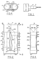
- Fig. 1 illustrates, in a schematic fashion, usage of the device in an air induction system.
- Fig. 2 illustrates a longitudinal plan view of the device.
- Fig. 3 is a longitudinal view taken in the direction of arrows 3-3 in Fig. 2.
- Fig. 4 is an end view taken in the direction of arrows 4-4 in Fig. 2.
- Fig. 1 presents an illustrative usage of an in-line noise attenuation device 10 in the air induction system 12 of an internal combustion engine 14.
- Device 10 is disposed in-line in induction system 12 so that atmospheric air that is sucked in by engine 14 passes through the device without significant restriction while the device causes significant attenuation of noise that propagates back through the system toward atmosphere. Details of device 10 are presented in Figs 2-4.
- Device 10 is a single plastic part that contains an entrance end portion 16 that is toward atmosphere and an exit end portion 18 that is toward engine 14. It also contains a first venturi portion 20 and a second venturi portion 22, which are arranged side-by-side in parallel flow relation between end portions 16 and 18. Venturi portion 20 is symmetric about a longitudinal axis 15 while venturi portion 22 is symmetric about a longitudinal axis 17, both said axes being parallel with and equidistant from a main central longitudinal axis 19 of the device.
- Each end portion 16, 18 comprises a terminal end portion, 16a, 18a respectively, having a tubular wall, whose transverse cross section may be considered to be in the shape of a racetrack, i.e. an elongated circle.
- hoses (not shown) forming at least a portion of the induction air system are fitted over terminal end portions 16a, 18a in a sealed manner so that induction air is conveyed to entrance end portion 16 and from exit end portion 18 as it passes through induction system 12.
- venturi section 20 comprises, in succession, a converging frustoconically walled section 20a, a diverging frustoconically walled section 20b, a converging frustoconically walled section 20c, and a diverging frustoconically walled section 20d.
- section 20a has a radius that is equal to the radius of the semi-circular end of the race-track-shaped terminal end portion 16a into which the semi-circular half of section 20a that is farthest from axis 19 merges, both radii lying on axis 15.
- Transition section 18b via which section 20d merges with terminal end portion 18a.
- Transition section 18b has a uniform circular transverse cross section whose radius is equal to the radius of the semi-circular end of the race-track-shaped terminal end portion 18a into which the semi-circular half of section 18b that is farthest from axis 19 merges, these respective radii also lying on axis 15. This configuration results in a transverse wall portion 24 bounding the semi-circular portion of section 18b that is nearest axis 19.
- venturi section 22 comprises, in succession, a converging frustoconically walled section 22a, a diverging frustoconically walled section 22b, a converging frustoconically walled section 22c, and a diverging frustoconically walled section 22d.
- a transition section 16b via which section 22a merges with terminal end portion 16a.
- Transition section 16b is of generally tubular shape; the half that is nearest axis 19 has a frustoconically tapered shape having a cone angle the same as that of section 22a and forming a continuation of the half of section 22a that is nearest axis 19; the half of section 16b that is farthest from axis 19 has a uniform semi-circular cross-sectional shape whose radius is equal to the radius of the semi-circular end of the race-track-shaped terminal end portion 16a with which it merges, both radii lying on axis 17.
- the radius of section 22d is equal to the radius of the semi-circular shaped end of terminal end portion 18 into which the half of section 22d that is farthest from axis 19 merges.
- the result of this configuration is a transverse wall 26 bounding the half of section 22d that is nearest axis 19 at the transition between section 22d and terminal end portion 18a, said wall 26 being contiguous, and merging, with wall 24.
- a final structural feature of the device is the presence of a smooth aerodynamically shaped wedge 28 within entrance portion 16.
- the function of wedge 28 is to separate the flow entering entrance 16 so that it splits into two streams through the respective venturis 20 and 22 without any appreciable entrance turbulence.
- Wedge 28 may be considered as comprising four wall portions designated 28a, 28b, 28c, and 28d in Fig. 4.
- Wall portions 28a, 28b form what amounts to an extension of the half of venturi section 20a that is nearer axis 19 while wall portions 28c, 28d do the same for the corresponding portion of transition section 16b.
- the portions 28a and 28d share a common apex 30 and the portions 28b and 28c share a common apex 31.
- each apex is asymmetrical with respect to axis 19 due to the fact that the mutual tangency of the entrance end of section 20a and the entrance end of transition portion 16b are also asymmetrical with respect to axis 19.
- the surface of each portion 28a, 28b, 28c, 28d is of a general concave shape defined in transverse cross section at any location along axis 19 by an arc that is concave toward the respective axis 15, 17, specifically axis 15 for sections 28a, 28b and axis 17 for sections 28c, 28d.
- the direction of noise propagation through the device is from exit end portion 18 to entrance end portion 16, a direction opposite the direction of air flow.
- air enters the device at entrance end portion 16 it separates into two more or less equal parts, one to flow through venturi section 20, the other through venturi section 22.
- the flows emerging from the venturi sections 20, 22 exit the device via exit end portion 18.
- Noise from engine 14 entering exit end portion 18 also tends to separate into two more or less equal parts, one to pass through venturi section 20, the other through venturi section 22.
- the venturi sections change the pressure and particle velocity, thereby changing the impedance or resistance to motion.
- the noise that propagates through venturi section 20 enters section 20 at a certain time interval after the noise that propagates through venturi section 22 enters section 22 because the two venturi sections 20 and 22 are relatively offset from each other in the direction of noise propagation.
- the effect of the relative axial offset of one to the other is to create a certain phase shift in each frequency component of the noise passing through one venturi section relative to a corresponding noise frequency component passing through the other venturi section by the time the noise emerges from entrance end portion 16. If it is assumed that the noise consists of a principal frequency component that is desired to be attenuated, then by making the relative axial offset between the two venturi sections 20, 22 equal to one-quarter of the wavelength of the principal frequency component, the device will have imposed on that principal frequency component a 180 degree relative phase shift between the noise that has propagated through venturi section 22 and that which has propagated through venturi section 20 by the time that the noise exits entrance end portion 16.
- the device In designing a specific embodiment of the device, it will be typical for the device to be designed for attenuation of a particular frequency of noise, and this is where the maximum attenuation will occur. Because noise often consists of a range of frequencies and/or harmonics, the device can also have a beneficial effect on noise frequencies other than the principal one. In other words, the device can be considered to possess certain bandwidth for noise attenuation.
- venturi sections should be exactly identical. It is not essential however that a device that has more than one venturi in a venturi section have those venturis exactly identical even though the device which has been illustrated and described herein comprises two exactly identical venturis in each venturi section. Substantial identity of the venturi sections is sufficient. Likewise, a device embodying principles of the invention can be used not only where the noise propagates counter to the gas flow, but also where the noise propagates in the same direction as the gas flow.
- the illustrated device is also advantageous because it can be fabricated as a single plastic part, other devices can be composed of multiple parts.
Landscapes
- Engineering & Computer Science (AREA)
- Chemical & Material Sciences (AREA)
- Combustion & Propulsion (AREA)
- Mechanical Engineering (AREA)
- General Engineering & Computer Science (AREA)
- Exhaust Silencers (AREA)
- Lubrication Details And Ventilation Of Internal Combustion Engines (AREA)
- Operation Control Of Excavators (AREA)
- Blow-Moulding Or Thermoforming Of Plastics Or The Like (AREA)
- Jet Pumps And Other Pumps (AREA)
Claims (9)
- Verfahren zum Dämpfen von durch eine gasführende Leitung (12) wandernden Schall ohne merkliche Drosselung des Gasstromes, bei dem der Gasstrom in mehrere parallele Ströme aufgeteilt wird und dann die Ströme wiedervereinigt werden, dadurch gekennzeichnet, daß die Ströme nach dem Aufteilen, jedoch vor dem Wiedervereinigen durch entsprechende, im wesentlichen identische Venturi-Abschnitte (20, 22) geführt werden, die relativ zueinander axial versetzt angeordnet sind.
- Verfahren nach Anspruch 1, dadurch gekennzeichnet, daß der Strom in zwei Teile aufgeteilt wird, die durch zwei entsprechende, im wesentlichen identische Venturi-Abschnitte geführt werden, welche um im wesentlichen ein Viertel der Wellenlänge einer Hauptfrequenzkomponente des Schalls relativ zueinander axial versetzt sind.
- Vorrichtung (10) zum Durchführen des Verfahrens nach Anspruch 1 oder 2 mit einem Einlaßende (16) und einem Auslaßende (18), über die das Gas in die Vorrichtung eintritt bzw. sie verläßt, wobei Schall am einen Ende eintritt und am anderen Ende austritt, wobei die Vorrichtung im wesentlichen parallele Strömungskanäle zwischen dem Einlaßende und dem Auslaßende aufweist, dadurch gekennzeichnet, daß die im wesentlichen parallelen Strömungskanäle entsprechende, im wesentlichen identische Venturi-Abschnitte (20, 22) aufweisen, wobei der Schall durch die beiden Venturi-Abschnitte zwischen dem einen Ende und dem anderen Ende hindurchwandert, jeder der Venturi-Abschnitte mindestens eine Venturi-Düse aufweist, und ein Venturi-Abschnitt gegenüber dem anderen in Schallfortpflanzungsrichtung versetzt ist, um an dem besagten anderen Ende eine Phasenverschiebung zwischen dem Schall, der durch einen Venturi-Abschnitt gewandert ist, und dem Schall, der durch den anderen Venturi-Abschnitt gewandert ist, zu erzeugen, derart, daß zumindest ein Teil des Schalls, der durch den besagten einen Venturi-Abschnitt gewandert ist, zumindest einen Teil des Schalls, der durch den anderen Venturi-Abschnitt gewandert ist, auslöscht, wodurch der am anderen Ende der Vorrichtung austretende Schall erheblich gedämpft ist gegenüber dem bei Fehlen der Vorrichtung vorhandenen Schall.
- Vorrichtung nach Anspruch 3, dadurch gekennzeichnet, daß die Venturi-Abschnitte um ein Viertel der Wellenlänge einer Hauptfrequenzkomponente des Schalls axial versetzt zueinander sind.
- Vorrichtung nach Anspruch 3, dadurch gekennzeichnet, daß das Einlaßende und das Auslaßende im wesentlichen identische längliche Kreise sind, die auf einer gemeinsamen zentralen Achse (19) liegen, und jeder Venturi-Abschnitt seine eigene Achse (15, 17) hat, und daß die Achsen der Venturi-Abschnitte im wesentlichen parallel und im gleichen Abstand zu der zentralen Achse verlaufen.
- Vorrichtung nach Anspruch 5, gekennzeichnet durch einen aerodynamischen Keil (28), der innerhalb des Einlaßendes angeordnet ist, um die glatte Aufteilung des ankommenden Gasstromes zu begünstigen, damit er in Jeden Venturi-Abschnitt eintritt, ohne eine merkliche Einlaufturbulenz zu erzeugen.
- Vorrichtung nach Anspruch 6, dadurch gekennzeichnet, daß der aerodynamische Keil zu der zentralen Achse exzentrische Apices (30, 31) und konkave Wandabschnitte (28a, 28b, 28c, 28d) aufweist, die von den Apices zu den Venturi-Abschnitten verlaufen.
- Vorrichtung nach Anspruch 3, dadurch gekennzeichnet, daß das Einlaßende und das Auslaßende sowie die Venturi-Abschnitte aus einem einzigen blasgeformten Kunststoffteil bestehen.
- Vorrichtung nach Anspruch 8, gekennzeichnet durch einen aerodynamischen Keil (28), der innerhalb des Einlaßendes angeordnet ist, um die glatte Aufteilung des ankommenden Gasstromes zu begünstigen, damit er in jeden Venturi-Abschnitt eintritt, ohne eine merkliche Einlaufturbulenz zu erzeugen, wobei der aerodynamische Keil mit dem einzelnen blasgeformten Kunststoffteil einstückig ausgebildet ist.
Applications Claiming Priority (3)
| Application Number | Priority Date | Filing Date | Title |
|---|---|---|---|
| US07/439,712 US4934343A (en) | 1989-11-21 | 1989-11-21 | In-line noise attenuation device |
| US439712 | 1989-11-21 | ||
| PCT/EP1990/001881 WO1991007583A1 (en) | 1989-11-21 | 1990-11-09 | In-line noise attenuation device |
Publications (2)
| Publication Number | Publication Date |
|---|---|
| EP0505403A1 EP0505403A1 (de) | 1992-09-30 |
| EP0505403B1 true EP0505403B1 (de) | 1994-08-24 |
Family
ID=23745834
Family Applications (1)
| Application Number | Title | Priority Date | Filing Date |
|---|---|---|---|
| EP91900242A Expired - Lifetime EP0505403B1 (de) | 1989-11-21 | 1990-11-09 | In-line-geräuschdämpfungsvorrichtung |
Country Status (7)
| Country | Link |
|---|---|
| US (1) | US4934343A (de) |
| EP (1) | EP0505403B1 (de) |
| JP (1) | JP2824699B2 (de) |
| KR (1) | KR0171616B1 (de) |
| CA (1) | CA2069102A1 (de) |
| DE (1) | DE69011871T2 (de) |
| WO (1) | WO1991007583A1 (de) |
Families Citing this family (11)
| Publication number | Priority date | Publication date | Assignee | Title |
|---|---|---|---|---|
| DE4013848A1 (de) * | 1990-04-30 | 1991-10-31 | Vdo Schindling | Einrichtung zur daempfung des ansauggeraeusches bei dieselmotoren |
| US5163387A (en) * | 1991-10-07 | 1992-11-17 | Siemens Automotive Limited | Device for attenuating standing waves in an induction intake system |
| JP2611595B2 (ja) * | 1992-01-27 | 1997-05-21 | 三菱電機株式会社 | 空気調和装置 |
| US5176114A (en) * | 1992-04-20 | 1993-01-05 | Siemens Automotive Limited | Engine intake manifold tuning by active noise control |
| US5628287A (en) * | 1994-09-30 | 1997-05-13 | Siemens Electric Limited | Adjustable configuration noise attenuation device for an air induction system |
| RU2187667C2 (ru) * | 2000-07-17 | 2002-08-20 | Открытое акционерное общество "АВТОВАЗ" | Многоцилиндровый двигатель внутреннего сгорания |
| RU2187668C2 (ru) * | 2000-07-17 | 2002-08-20 | Открытое акционерное общество "АВТОВАЗ" | Многоцилиндровый двигатель внутреннего сгорания |
| US6558137B2 (en) * | 2000-12-01 | 2003-05-06 | Tecumseh Products Company | Reciprocating piston compressor having improved noise attenuation |
| US20090025393A1 (en) * | 2006-10-31 | 2009-01-29 | Karl Edward Sheldon | Auxiliary power unit assembly |
| DE102006061733A1 (de) * | 2006-12-28 | 2008-07-03 | Robert Bosch Gmbh | Halterungsvorrichtung für ein Reduktionsmittel-Dosierventil |
| JP2008114838A (ja) * | 2007-10-26 | 2008-05-22 | General Electric Co <Ge> | 補助動力装置組立体 |
Family Cites Families (9)
| Publication number | Priority date | Publication date | Assignee | Title |
|---|---|---|---|---|
| GB137829A (en) * | 1920-01-12 | 1921-04-12 | Richard Sloman | Improvements in means for eliminating or reducing the pulsation of gaseous currents,for silencing and other purposes |
| DE1199514B (de) * | 1962-05-12 | 1965-08-26 | Guenther Gerber | Schalldaempfer |
| FR1434675A (fr) * | 1965-05-13 | 1966-04-08 | Dispositif destiné à atténuer, voire supprimer le bruit provoqué par l'échappement d'un gaz sous pression | |
| US3948349A (en) * | 1975-05-12 | 1976-04-06 | General Motors Corporation | Wave interference silencer |
| FR2393163A1 (fr) * | 1977-05-30 | 1978-12-29 | Honda Motor Co Ltd | Appareil servant a supprimer les bruits d'aspiration d'un moteur a combustion interne |
| US4287962A (en) * | 1977-11-14 | 1981-09-08 | Industrial Acoustics Company | Packless silencer |
| JPS54148922A (en) * | 1978-05-13 | 1979-11-21 | Daihatsu Motor Co Ltd | Air intake device for automotive engine |
| US4359134A (en) * | 1980-12-05 | 1982-11-16 | American Hospital Supply Corporation | Sound suppressor for fluid flow lines |
| GB2203488A (en) * | 1987-04-04 | 1988-10-19 | Ford Motor Co | Manifold tuning for I.C. engines |
-
1989
- 1989-11-21 US US07/439,712 patent/US4934343A/en not_active Expired - Lifetime
-
1990
- 1990-11-09 JP JP3500625A patent/JP2824699B2/ja not_active Expired - Fee Related
- 1990-11-09 DE DE69011871T patent/DE69011871T2/de not_active Expired - Fee Related
- 1990-11-09 CA CA002069102A patent/CA2069102A1/en not_active Abandoned
- 1990-11-09 KR KR1019920701198A patent/KR0171616B1/ko not_active Expired - Fee Related
- 1990-11-09 EP EP91900242A patent/EP0505403B1/de not_active Expired - Lifetime
- 1990-11-09 WO PCT/EP1990/001881 patent/WO1991007583A1/en not_active Ceased
Also Published As
| Publication number | Publication date |
|---|---|
| JPH05503130A (ja) | 1993-05-27 |
| EP0505403A1 (de) | 1992-09-30 |
| WO1991007583A1 (en) | 1991-05-30 |
| US4934343A (en) | 1990-06-19 |
| KR0171616B1 (ko) | 1999-03-20 |
| DE69011871T2 (de) | 1995-02-23 |
| JP2824699B2 (ja) | 1998-11-11 |
| DE69011871D1 (de) | 1994-09-29 |
| CA2069102A1 (en) | 1991-05-22 |
| KR920703995A (ko) | 1992-12-18 |
Similar Documents
| Publication | Publication Date | Title |
|---|---|---|
| EP0505403B1 (de) | In-line-geräuschdämpfungsvorrichtung | |
| US4809812A (en) | Converging, corridor-based, sound-attenuating muffler and method | |
| US4936413A (en) | In-line noise attenuation device for a gas conduit | |
| US7093589B2 (en) | Apparatus for increasing induction air flow rate to a turbocharger | |
| US4580657A (en) | Integral fluted tube for sound suppression and exhaust ejection | |
| US4574914A (en) | Compact, sound-attenuating muffler for high-performance, internal combustion engine | |
| CN101372929B (zh) | 旋流发生器 | |
| JP2749680B2 (ja) | インライン絞り消音システム | |
| US4418788A (en) | Branch take-off and silencer for an air distribution system | |
| TW201704628A (zh) | 汽車內燃機的排氣系統 | |
| JPH07101002B2 (ja) | 共鳴型消音器 | |
| US4697668A (en) | Aspirating muffler | |
| US6464036B1 (en) | Air intake silencer | |
| TWI734497B (zh) | 工業設備及氣旋式排風裝置 | |
| US4131439A (en) | Device for the dedusting of dust-containing gases | |
| US6305493B1 (en) | Exhaust system for internal combustion engines | |
| GB2041083A (en) | Silencer for an internal combustion engine | |
| KR100306187B1 (ko) | 엔진의배기가스재순환장치및egr장치를구비한엔진장치 | |
| US2489585A (en) | Baffle type muffler with fluid mingling | |
| EP0244335B1 (de) | Diffusor | |
| GB2267359A (en) | Improvements in attenuating bends | |
| JP5569627B2 (ja) | ミキシング装置 | |
| RU2087727C1 (ru) | Выхлопное устройство двигателя внутреннего сгорания транспортного средства | |
| SU1379579A2 (ru) | Приточно-выт жное вентил ционное устройство | |
| CA2319292C (en) | An air intake silencer |
Legal Events
| Date | Code | Title | Description |
|---|---|---|---|
| PUAI | Public reference made under article 153(3) epc to a published international application that has entered the european phase |
Free format text: ORIGINAL CODE: 0009012 |
|
| 17P | Request for examination filed |
Effective date: 19920730 |
|
| AK | Designated contracting states |
Kind code of ref document: A1 Designated state(s): DE FR GB IT SE |
|
| 17Q | First examination report despatched |
Effective date: 19930907 |
|
| GRAA | (expected) grant |
Free format text: ORIGINAL CODE: 0009210 |
|
| AK | Designated contracting states |
Kind code of ref document: B1 Designated state(s): DE FR GB IT SE |
|
| REF | Corresponds to: |
Ref document number: 69011871 Country of ref document: DE Date of ref document: 19940929 |
|
| ITF | It: translation for a ep patent filed | ||
| PG25 | Lapsed in a contracting state [announced via postgrant information from national office to epo] |
Ref country code: SE Effective date: 19941124 |
|
| ET | Fr: translation filed | ||
| PLBE | No opposition filed within time limit |
Free format text: ORIGINAL CODE: 0009261 |
|
| STAA | Information on the status of an ep patent application or granted ep patent |
Free format text: STATUS: NO OPPOSITION FILED WITHIN TIME LIMIT |
|
| 26N | No opposition filed | ||
| REG | Reference to a national code |
Ref country code: GB Ref legal event code: IF02 |
|
| PGFP | Annual fee paid to national office [announced via postgrant information from national office to epo] |
Ref country code: DE Payment date: 20020121 Year of fee payment: 12 |
|
| PGFP | Annual fee paid to national office [announced via postgrant information from national office to epo] |
Ref country code: GB Payment date: 20021107 Year of fee payment: 13 |
|
| PGFP | Annual fee paid to national office [announced via postgrant information from national office to epo] |
Ref country code: FR Payment date: 20021129 Year of fee payment: 13 |
|
| PG25 | Lapsed in a contracting state [announced via postgrant information from national office to epo] |
Ref country code: DE Free format text: LAPSE BECAUSE OF NON-PAYMENT OF DUE FEES Effective date: 20030603 |
|
| PG25 | Lapsed in a contracting state [announced via postgrant information from national office to epo] |
Ref country code: GB Free format text: LAPSE BECAUSE OF NON-PAYMENT OF DUE FEES Effective date: 20031109 |
|
| GBPC | Gb: european patent ceased through non-payment of renewal fee |
Effective date: 20031109 |
|
| PG25 | Lapsed in a contracting state [announced via postgrant information from national office to epo] |
Ref country code: FR Free format text: LAPSE BECAUSE OF NON-PAYMENT OF DUE FEES Effective date: 20040730 |
|
| REG | Reference to a national code |
Ref country code: FR Ref legal event code: ST |
|
| PG25 | Lapsed in a contracting state [announced via postgrant information from national office to epo] |
Ref country code: IT Free format text: LAPSE BECAUSE OF NON-PAYMENT OF DUE FEES;WARNING: LAPSES OF ITALIAN PATENTS WITH EFFECTIVE DATE BEFORE 2007 MAY HAVE OCCURRED AT ANY TIME BEFORE 2007. THE CORRECT EFFECTIVE DATE MAY BE DIFFERENT FROM THE ONE RECORDED. Effective date: 20051109 |