EP0505347B1 - Verfahren zur Abscheidung von polychlorierten Dioxinen und Furanen aus Gasen - Google Patents
Verfahren zur Abscheidung von polychlorierten Dioxinen und Furanen aus Gasen Download PDFInfo
- Publication number
- EP0505347B1 EP0505347B1 EP92890054A EP92890054A EP0505347B1 EP 0505347 B1 EP0505347 B1 EP 0505347B1 EP 92890054 A EP92890054 A EP 92890054A EP 92890054 A EP92890054 A EP 92890054A EP 0505347 B1 EP0505347 B1 EP 0505347B1
- Authority
- EP
- European Patent Office
- Prior art keywords
- gas
- furans
- dioxins
- filter
- cooled
- Prior art date
- Legal status (The legal status is an assumption and is not a legal conclusion. Google has not performed a legal analysis and makes no representation as to the accuracy of the status listed.)
- Expired - Lifetime
Links
Images
Classifications
-
- B—PERFORMING OPERATIONS; TRANSPORTING
- B01—PHYSICAL OR CHEMICAL PROCESSES OR APPARATUS IN GENERAL
- B01D—SEPARATION
- B01D53/00—Separation of gases or vapours; Recovering vapours of volatile solvents from gases; Chemical or biological purification of waste gases, e.g. engine exhaust gases, smoke, fumes, flue gases, aerosols
- B01D53/34—Chemical or biological purification of waste gases
- B01D53/46—Removing components of defined structure
- B01D53/68—Halogens or halogen compounds
- B01D53/70—Organic halogen compounds
Definitions
- the invention relates to a process for the separation of polychlorinated dioxins and furans from gases in small to medium and / or batch-operated plants, and to a plant for carrying out the process.
- the safety precautions in particular represent fixed costs, which are incurred regardless of the size of the system, and result in high specific costs for small and medium-sized systems, based on the amount of gas disposed of. This economic disadvantage is even more evident in batch-operated systems, since the auxiliary systems mentioned must be started up or shut down at the beginning or at the end of each use of the system.
- Cleaning systems using Akoks filters i.e. Filters based on activated carbon are operated at temperatures around 80 ° C, whereby extensive monitoring and safety devices are necessary due to the risk of ignition.
- the oxidation catalysts which are also used, work at temperatures of around 280 ° C, which usually requires a system for heating the gas, and require further additional systems for producing the uniform, dust-free gas stream required for operation.
- Flue gas cleaning systems consisting of a spray dryer and a downstream electrostatic precipitator, show very good separation results and are susceptible to malfunction during operation, so that reliable dioxin separation cannot be guaranteed. Therefore, these systems are also not economical for the target group of the present invention.
- the reduction in the flue gas temperature is, however, limited to around 120 ° C, since this is where the dew point of the flue gas is usually reached, but dust must be removed dry.
- the principle of diluting and cooling flue gas with filtered and solid-free cooling gas is also described in a method for measuring solids in exhaust gases according to DE-A-31 36 646. However, the method described last is a measurement method in which small samples, i.e. small gas volumes taken from an exhaust gas stream and analyzed in a complicated apparatus using, for example, flow meters and gas meters for the sample gas volume or the cooling gas.
- the object of the present invention is therefore to specify a method and a device which are specifically intended for the separation of dioxins and furans in small to medium-sized and / or batch-operated systems and which work in the simplest and most economical manner, in which none solid or liquid hazardous waste is produced, and it is advantageously possible to use conventional system parts, for example filters.
- the entire gas is fed to a mixing chamber in which the gas is mixed with a cooling gas in a manner known per se and is thereby cooled to 30 to 60 ° C. and the cooled gas mixture is fed to a paraffin-impregnated dust filter, in which the dioxins and furans are separated from the cooled gas mixture.
- the filter elements of the conventionally used dust filters can be fed to a combustion or pyrolysis plant in order to remove the pollutants attached to them to destroy thermally and thus to prevent the formation of solid or liquid hazardous waste.
- the method according to the invention does not require long start-up or decay times, so that it can also be usefully used in small or batch-operated systems.
- the temperature of the gas mixture is set to 30 to 60 ° C. and preferably its relative humidity to a maximum of 80%.
- a system which is characterized by a mixing chamber in the gas line, a device for admixing a cooling gas and a paraffin-impregnated dust filter in which the dioxins and furans from the cooled gas mixture accumulate.
- This system has the advantage that it is simple in construction and therefore does not require any major modifications to the systems to be equipped, and that conventionally used individual elements can be used for the most part.
- a paraffin-impregnated dust filter with a coarse surface preferably a paper pleated filter, is provided, which increases the separating surface and preferably absorbs the lipophilic dioxin in the paraffin.
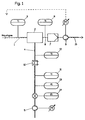
- the flue gas is fed via a line 1 to a mixing chamber 2.
- a temperature measurement sensor 3 for determining the temperature of the flue gas is also provided in the flue gas feed line 1.
- a line 4 is used to supply cooling gas into the mixing chamber 2. Air is preferably used as the cooling gas.
- a controllable blower 5 is provided for the air supply, in order to adapt the amount of air supplied to the demand, which is determined from the desired temperature reduction or the desired mixing ratio between flue gas and air.
- a temperature sensor 8 is also provided, with which it is monitored whether the gas mixture also has the temperature required for optimal operation of the filter 7.
- a controllable blower 9 is arranged after the filter 7, through which the gas mixture is sucked through the filter 7 and then discharged further.
- a heat exchanger 10 can advantageously be provided in the supply line 4 for the cooling air if it is determined by a temperature sensor 11 that the cooling air is too high to be able to achieve the desired temperature reduction of the flue gas.
- a further temperature sensor 12 is preferably present in the line 4 after the heat exchanger 10 in order to reliably determine whether the desired air temperature has been obtained by the heat exchanger 10.
- a pressure sensor 13 and a flow meter 14 are advantageously also provided in the supply line 4 for the cooling air.
- the controllable blower 9 which draws the gas mixture through the filter 7 and delivers it via a line 15 either directly to the environment or to downstream additional treatment plants, can advantageously be connected to a sensor on the feed line 1 for the flue gas. This is symbolized by the dashed line in the illustration. This means that even with changing pressure or
- the power of the blower 9 are regulated in such a way that relatively uniform flow conditions prevail in the mixing chamber 2 or in the filter 7. This, in turn, is advantageous for the separation performance of the filter 7.
- the monitoring of the temperature or pressure value as well as their regulation is preferably carried out by an automatic process control system, especially microprocessor-controlled.
- the flue gas coming from the pyrolysis plant is saturated with water, while sulfur dioxide and hydrochloric acid have already been separated in a washing plant.
- the flue gas has a maximum dust content of 100 mg / m3 and the dioxin emissions are greater than 0.1 ng / m3.
- the flue gas is diluted with air in a mixing chamber and cooled, with the flue gas temperature and the temperature in the dust filter, as well as the amount of air to be supplied, being measured or readjusted every second.
- the supply air is injected normally to the flue gas and then complete mixing is achieved using baffles.
- the dust filter designed as a paper pleated filter, the dust is completely separated and polychlorinated dioxin or furan in the gas phase is adsorbed on the paper.
- the paper pleated filter also represents a safety filter for separating fine dust and soot particles that break through.
- the elements of the paper pleated filter are disposed of at regular intervals, preferably depending on the dust load of the flue gas and the dioxin emission, by returning them to the pyrolysis plant. 99% of the dioxin adsorbed on the elements is destroyed, the rest escaping is in turn adsorbed in the pleated filter.
Landscapes
- Engineering & Computer Science (AREA)
- Chemical & Material Sciences (AREA)
- Health & Medical Sciences (AREA)
- Biomedical Technology (AREA)
- Environmental & Geological Engineering (AREA)
- Analytical Chemistry (AREA)
- General Chemical & Material Sciences (AREA)
- Oil, Petroleum & Natural Gas (AREA)
- Chemical Kinetics & Catalysis (AREA)
- Treating Waste Gases (AREA)
- Organic Low-Molecular-Weight Compounds And Preparation Thereof (AREA)
Description
- Die Erfindung betrifft eine Verfahren zur Abscheidung von polychlorierten Dioxinen und Furanen aus Gasen bei kleinen bis mittleren und/oder batch-betriebenen Anlagen, sowie eine Anlage zur Durchführung des Verfahrens.
- Die derzeit verwendeten Systeme zur Entfernung von polychlorierten Dioxinen und Furanen von Gasen, insbesondere von Rauchgasen, benötigen für ihren störungsfreien Betrieb staubfreies Gas und setzen umfangreiche Sicherheitsvorkehrungen bzw. Anlagen zur Voraufbereitung des zu reinigenden Gases voraus. Insbesondere die Sicherheitsvorkehrungen stellen Fixkosten dar, welche unabhängig von der Anlagengröße anfallen und bewirken bei kleinen und mittleren Anlagen hohe spezifische Kosten, bezogen auf die entsorgte Gasmenge. Dieser wirtschaftliche Nachteil tritt bei batchbetriebenen Anlagen noch stärker zutage, da die angesprochenen Hilfsanlagen am Anfang bzw. am Ende eines jeden Einsatzes der Anlage an- bzw. abgefahren werden müssen.
- Reinigungssysteme, welche Akoks-Filter verwenden, d.h. Filter auf der Basis von Aktivkohle, werden bei Temperaturen um 80°C betrieben, wobei wegen der Entzündungsgefahr umfangreiche Uberwachungs- und Sicherheitseinrichtungen notwendig sind. Andererseits arbeiten die ebenfalls verwendeten Oxidationskatalysatoren bei Temperaturen um 280°C, was meist eine Anlage zur Aufheizung des Gases voraussetzt, und bedürfen weitere Zusatzanlagen zur Herstellung des für den Betrieb notwendigen gleichmäßigen staubfreien Gasstromes. Auch Rauchgasreinigungssysteme, bestehend aus einem Sprühtrockner und einem nachgeschalteten Elektrofilter zeigen sehr gute Abscheideergebnisse, sind im Betrieb störanfällig, sodaß eine zuverlässige Dioxinabscheidung nicht garantiert werden kann. Daher sind diese Systeme für die Zielgruppe der vorliegenden Erfindung ebenfalls nicht wirtschaftlich.
- Auf dem Gebiet der Abscheidung von Dioxinen ist es bekannt, daß durch Minderung der Rauchgastemperatur in ebenfalls üblichen Schlauchfiltern eine Senkung der Dioxinemission eintritt, d.h. die Abscheideleistung ist dadurch verbessert.
- Die Minderung der Rauchgastemperatur ist jedoch bei etwa 120°C limitiert, da hier meist der Taupunkt des Rauchgases erreicht wird, die Staubabscheidung jedoch trocken erfolgen muß. Auch bei einem Verfahren zum Messen von Feststoffen in Abgasen gemäß der DE-A-31 36 646 wird das Prinzip des Verdünnens und Kühlens von Rauchgas mit gefiltertem und feststofffreiem Kühlgas beschrieben. Bei dem zuletzt beschriebenen Verfahren handelt es sich jedoch um ein Meßverfahren, bei welchem kleine Proben, d.h. kleine Gasvolumen aus einem Abgasstrom entnommen und in einer komplizierten Apparatur unter Verwendung von beispielsweise Durchflußmessern und Gaszählern für das Probegasvolumen bzw. das Kühlgas analysiert.
- Die Aufgabe der vorliegenden Erfindung ist daher ein Verfahren sowie eine Vorrichtung, welche speziell für die Abscheidung von Dioxinen und Furanen bei kleinen bis mittleren und/oder batch-betriebenen Anlagen bestimmt ist, anzugeben, welche auf möglichst einfache und wirtschaftliche Weise arbeiten, bei welchen kein fester oder flüssiger Sondermüll entsteht, und wobei vorteilhafterweise gebräuchliche Anlagenteile, beispielsweise Filter, verwendet werden können.
- Zur Lösung dieser Aufgabe ist erfindungsgemäß vorgesehen, daß das gesamte Gas einer Mischkammer zugeleitet wird, in welcher das Gas in an sich bekannter Weise mit einem Kühlgas gemischt und dadurch auf 30 bis 60°C abgekühlt wird und das gekühlte Gasgemisch einem paraffinimprägnierten Staubfilter zugeleitet wird, in dem die Dioxine und Furane aus dem gekühlten Gasgemisch abgeschieden werden.
- Dadurch wird gewährleistet, daß die Temperatur des zu reinigenden Gases dermaßen abgesenkt wird, daß ein nachgeschaltetes paraffinimprägniertes Staubfilter die im Gas enthaltenen Dioxine und Furane ausfiltern kann, und dabei keine Kondensation des Dampfes erfolgt. Die Filterelemente der herkömmlich verwendeten Staubfilter können einer Verbrennungs- oder Pyrolyseanlage zugeführt werden, um die daran angelagerten Schadstoffe thermisch zu zerstören und somit die Entstehung festen oder flüssigen Sondermülls zu verhindern. Das erfindungsgemäße Verfahren bedarf keiner langen Anlauf- oder Abklingzeiten, sodaß es auch bei kleinen bzw. batch-betriebenen Anlagen sinnvoll einsetzbar ist.
- Um aufwendige Sicherheitsvorkehrungen zu vermeiden und gleichzeitig die Abscheideleistung zu optimieren ist vorgesehen, daß die Temperatur des Gasgemisches auf 30 bis 60°C und vorzugsweise seine relative Feuchte auf maximal 80% eingestellt wird.
- Zur Durchführung des erfindungsgemäßen Verfahrens ist vorteilhafterweise eine Anlage vorgesehen, welche gekennzeichnet ist durch eine Mischkammer in der Gasleitung, eine Einrichtung zur Zumischung eines Kühlgases und einen paraffinimprägnierten Staubfilter, in welchem sich die Dioxine und Furane aus dem gekühlten Gasgemisch anlagern.
- Diese Anlage hat den Vorteil, daß sie einfach aufgebaut ist und daher keiner großen Umrüstungen der auszustattenden Anlagen bedarf, und daß zum Großteil herkömmlich verwendete Einzelelemente Verwendung finden können.
- Um die Abscheidung sowohl der an Staubpartikeln adsorbierten als auch der noch gasförmig vorliegenden Schadstoffe zu gewährleisten, ist ein mit Paraffin imprägniertes Staubfilter mit grober Oberfläche, vorzugsweise ein Papierfaltenfilter, vorgesehen, wodurch die abscheidewirksame Oberfläche erhöht und vorzugsweise das lipophile Dioxin im Paraffin absorbiert wird.
- Ein Ausführungsbeispiel der Erfindung soll anhand einer schematischen Darstellung einer erfindungsgemäßen Anlage zur Rauchgas-Reinigung beispielhaft näher erläutert werden.
- Das Rauchgas wird über eine Leitung 1 einer Mischkammer 2 zugeführt. In der Rauchgaszuleitung 1 ist auch ein Temperaturmeßsensor 3 zur Ermittlung der Temperatur des Rauchgases vorgesehen. Eine Leitung 4 dient zur Zuführung von Kühlgas in die Mischkammer 2. Vorzugsweise wird Luft als Kühlgas verwendet. Zur Luftzuführung ist ein regelbares Gebläse 5 vorgesehen, um die zugeführte Luftmenge dem Bedarf anzupassen, welcher aus der gewünschten Temperaturerniedrigung bzw. dem gewünschten Mischungsverhältnis zwischen Rauchgas und Luft bestimmt wird. In einer Verbindungsleitung 6, durch welche das Gasgemisch in den Filter 7 gelangt, ist ebenfalls ein Temperatursensor 8 vorgesehen, mit welchem überwacht wird, ob das Gasgemisch auch die für den optimalen Betrieb des Filters 7 erforderliche Temperatur aufweist. Nach dem Filter 7 ist ein regelbares Gebläse 9 angeordnet, durch welches das Gasgemisch durch den Filter 7 gesaugt und anschließend weiter abgegeben wird.
- Vorteilhafterweise kann in der Zufuhrleitung 4 für die Kühlluft ein Wärmetauscher 10 vorgesehen sein, falls durch einen Temperatursensor 11 festgestellt wird, daß die Kühlluft eine zu hohe Temperatur aufweist, um die gewünschte Temperaturabsenkung des Rauchgases erzielen zu können. Bei dieser Ausführungsform ist vorzugsweise nach dem Wärmetauscher 10 ein weiterer Temperatursensor 12 in der Leitung 4 vorhanden, um sicher festzustellen, ob die gewünschte Lufttemperatur durch den Wärmetauscher 10 erhalten wurde.
- Vorteilhafterweise sind in der Zufuhrleitung 4 für die Kühlluft noch ein Drucksensor 13 sowie ein Durchflußmesser 14 vorgesehen.
- Das regelbare Gebläse 9, welches das Gasgemisch durch den Filter 7 ansaugt und über eine Leitung 15 entweder direkt an die Umgebung oder an nachgeschaltete zusätzliche Aufbereitungsanlagen abgibt, kann vorteilhafterweise mit einem Sensor an der Zufuhrleitung 1 für das Rauchgas verbunden sein. Dies ist durch die strichlierte Linie in der Abbildung symbolisiert. Dadurch kann auch bei wechselndem Druck bzw.
- Strömungsverhältnissen des zu reinigenden Rauchgases die Leistung des Gebläses 9 derart geregelt werden, daß in der Mischkammer 2 bzw. im Filter 7 relativ gleichmäßige Strömungsverhältnisse herrschen. Dies ist wiederum für die Abscheideleistung des Filters 7 von Vorteil.
- Die Überwachung des Temperatur- bzw. Druckwertes als auch deren Regelung wird vorzugsweise von einem automatischen Prozeßleitsystem, speziell mikroprozessorengesteuert, übernommen.
- Das aus der Pyrolyseanlage kommende Rauchgas ist mit Wasser gesättigt, während Schwefeldioxid und Salzsäure bereits in einer Waschanlage abgeschieden wurden. Das Rauchgas hat einen Staubgehalt von maximal 100 mg/m³ und die Dioxinemissionen sind größer als 0.1 ng/m³. Zur Dioxinabscheidung wird das Rauchgas in einer Mischkammer mit Luft verdünnt und gekühlt, wobei die Rauchgastemperatur und die Temperatur im Staubfilter sowie die zuzuführende Luftmenge in Sekundentakt gemessen bzw. nachgeregelt wird. In der Mischkammer wird die Zuluft normal zum Rauchgas eingedüst und anschließend wird mittels Leitblechen eine vollständige Durchmischung herbeigeführt.
- Im als Papierfaltenfilter ausgelegten Staubfilter wird der Staub vollständig abgeschieden und in der Gasphase befindliches polychloriertes Dioxin bzw. Furan am Papier adsorbiert.
- Das Papierfaltenfilter stellt gleichzeitig ein Sicherheitsfilter zur Abscheidung von Feinstaub und durchbrechenden Rußpartikeln dar.
- Die Elemente des Papierfaltenfilters werden in regelmäßigen Abständen vorzugsweise abhängig von der Staubbeladung des Rauchgases und der Dioxinemission durch Rückführung in die Pyrolyseanlage entsorgt. Das an den Elementen adsorbierte Dioxin wird dabei zu 99% zerstört, der entweichende Rest wird wiederum im Faltenfilter adsorbiert.
Claims (6)
- Verfahren zur Abscheidung von polychlorierten Dioxinen und Furanen aus Gasen bei kleinen bis mittleren und/oder batch-betriebenen Anlagen, dadurch gekennzeichnet, daß das gesamte Gas einer Mischkammer zugeleitet wird, in welcher das Gas in an sich bekannter Weise mit einem Kühlgas gemischt und dadurch auf 30 bis 60°C abgekühlt wird, und das gekühlte Gasgemisch einem paraffinimprägnierten Staubfilter zugeleitet wird, in dem die Dioxine und Furane aus dem gekühlten Gasgemisch abgeschieden werden.
- Verfahren gemäß Anspruch 1, dadurch gekennzeichnet, daß die relative Feuchte des Gasgemisches auf maximal 80% eingestellt wird.
- Verfahren gemäß Anspruch 1, dadurch gekennzeichnet, daß die Staubfilter-Elemente nach einer bestimmten Einsatzzeit zur Zerstörung der abgeschiedenen Dioxine und Furane einer Verbrennungs- bzw. Pyrolyseanlage zugeführt werden.
- Anlage zur Abscheidung von polychlorierten Dioxinen und Furanen aus Gasen bei kleinen bis mittleren und/oder batch-betriebenen Anlagen, gekennzeichnet durch eine Mischkammer in der Gasleitung, eine Einrichtung (5) zur Zumischung eines Kühlgases und einen Staubfilter (7), in welchem sich die Dioxine und Furane aus dem gekühlten Gasgemisch an den paraffinimprägnierten Filterteilen anlagern.
- Anlage gemäß Anspruch 4, dadurch gekennzeichnet, daß die Zufuhrleitung (4) für das Kühlgas im wesentlichen senkrecht zur Richtung der Gasströmung in die Gasleitung (1) einmündet.
- Anlage gemäß Anspruch 4, dadurch gekennzeichnet, daß der Staubfilter (7) ein Faltenfilter, vorzugsweise ein Papierfaltenfilter ist.
Applications Claiming Priority (2)
| Application Number | Priority Date | Filing Date | Title |
|---|---|---|---|
| AT632/91 | 1991-03-21 | ||
| AT0063291A AT395117B (de) | 1991-03-21 | 1991-03-21 | Verfahren zur abscheidung von polychlorierten dioxinen und furanen aus gasen bei kleinen bis mittleren und/oder batch-betriebenen anlagen sowie eine anlage zur durchfuehrung des verfahrens |
Publications (2)
| Publication Number | Publication Date |
|---|---|
| EP0505347A1 EP0505347A1 (de) | 1992-09-23 |
| EP0505347B1 true EP0505347B1 (de) | 1995-05-24 |
Family
ID=3495729
Family Applications (1)
| Application Number | Title | Priority Date | Filing Date |
|---|---|---|---|
| EP92890054A Expired - Lifetime EP0505347B1 (de) | 1991-03-21 | 1992-03-11 | Verfahren zur Abscheidung von polychlorierten Dioxinen und Furanen aus Gasen |
Country Status (3)
| Country | Link |
|---|---|
| EP (1) | EP0505347B1 (de) |
| AT (2) | AT395117B (de) |
| DE (1) | DE59202284D1 (de) |
Family Cites Families (6)
| Publication number | Priority date | Publication date | Assignee | Title |
|---|---|---|---|---|
| DE3136646C2 (de) * | 1981-09-16 | 1983-07-14 | Rheinisch-Westfälischer Technischer Überwachungsverein e.V ., 4300 Essen | Verfahren und Vorrichtung zum Messen von Feststoffen in Abgasen |
| US4502396A (en) * | 1983-04-25 | 1985-03-05 | Teller Environmental Systems, Inc. | Control of dioxin emissions from incineration |
| DE3628403A1 (de) * | 1986-06-20 | 1988-02-25 | Hoelter Heinz | Abscheidung durch chemische absorption von hochgiftigen schadstoffbelastungen, wie z.b. dioxine, furane, formaldehyde, pah's sowie weiteren giftigen stoffen |
| US4844875A (en) * | 1987-10-13 | 1989-07-04 | Westinghouse Electric Corp. | Fly ash recycling to reduce toxic gaseous emissions |
| DE3841858C1 (de) * | 1988-12-13 | 1989-10-26 | Kernforschungszentrum Karlsruhe Gmbh, 7500 Karlsruhe, De | |
| DE4018408A1 (de) * | 1990-06-08 | 1991-12-12 | Gore W L & Ass Gmbh | Anordnung zur abfuehrung von ofengasen |
-
1991
- 1991-03-21 AT AT0063291A patent/AT395117B/de not_active IP Right Cessation
-
1992
- 1992-03-11 AT AT92890054T patent/ATE122917T1/de not_active IP Right Cessation
- 1992-03-11 EP EP92890054A patent/EP0505347B1/de not_active Expired - Lifetime
- 1992-03-11 DE DE59202284T patent/DE59202284D1/de not_active Expired - Fee Related
Also Published As
| Publication number | Publication date |
|---|---|
| EP0505347A1 (de) | 1992-09-23 |
| ATA63291A (de) | 1992-02-15 |
| DE59202284D1 (de) | 1995-06-29 |
| ATE122917T1 (de) | 1995-06-15 |
| AT395117B (de) | 1992-09-25 |
Similar Documents
| Publication | Publication Date | Title |
|---|---|---|
| DE69624904T2 (de) | Verfahren und Vorrichtung zum Behandeln von Verbrennungsabgasen | |
| DE4023030C2 (de) | Trockenverfahren zur Behandlung von Verbrennungsabgasen | |
| DE69125007T2 (de) | Verfahren, vorrichtung und system für die behandlung von rauchgas | |
| EP0519225B1 (de) | Verfahren und Vorrichtung zum Reinigen von Abgasen aus Ofenanlagen | |
| EP0386806A2 (de) | Vorrichtung zur Abscheidung flüssiger Asche | |
| WO1985002453A1 (fr) | Procede de separation de gaz polluants acides et installation de combustion | |
| DE3625992A1 (de) | Verfahren zum verbrennen von kohlenstoffhaltigen materialien in einer zirkulierenden wirbelschicht und wirbelschichtfeuerungsanlage zur durchfuehrung des verfahrens | |
| EP2078555A1 (de) | Verfahren zur reinigung von Abgasen | |
| EP0359931B1 (de) | Verfahren zur Trennung von dampfförmigen Schwermetallverbindungen von einem Trägergas und Vorrichtung zur Durchführung des Verfahrens | |
| DE2928061A1 (de) | Verfahren zur abgasbehandlung | |
| DE2724372C2 (de) | Verfahren zum Konditionieren von Bypaßgasen | |
| EP3389828B1 (de) | Verfahren zur separierung von gasförmigen und partikelförmigen stoffen aus einem gasstrom mittels eines wirbelschichtströmungsreaktors | |
| DE3629688C2 (de) | Verfahren zur Reinigung von Rauch- und anderen Industrieabgasen | |
| EP0716264A2 (de) | Verfahren zur Verbrennung von Klärschlamm und Anlage zur Durchführung des Verfahrens | |
| DE3609025A1 (de) | Verfahren zur verringerung der so(pfeil abwaerts)2(pfeil abwaerts)-emission von mit fossilen brennstoffen befeuerten kesseln | |
| AT505542A4 (de) | Anlage zur reinigung der rauchgase eines ofens | |
| DE69522635T2 (de) | Methode eine Denitrierungsvorrichtung für einen kohlegefeuerten Kessel zu betreiben | |
| DE3234796C2 (de) | Verfahren und Vorrichtung zum Abscheiden von gasförmigen Schadstoffen aus Rauchgasen mittels staubförmiger Additive | |
| EP0505347B1 (de) | Verfahren zur Abscheidung von polychlorierten Dioxinen und Furanen aus Gasen | |
| EP0412591A1 (de) | Verfahren zur Abscheidung von Alkali- und Schwermetallverbindungen aus heissen Gasen | |
| DE3520885C3 (de) | Verfahren und Anlage zur weitgehenden Restentfernung von gasförmigen, aerosolartigen und/oder staubförmigen Schadstoffen | |
| DE3048764C2 (de) | Vorrichtung zum Entfernen radioaktiver Feststoffteilchen aus Naßgas | |
| DE69931924T2 (de) | Verfahren zur reinigung von abgas | |
| EP0274037A1 (de) | Verfahren und Vorrichtung zur Trennung von Partikeln | |
| DE2650491C2 (de) | Gas-Dampf-Turbinenanlage zur Erzeugung elektrischer Energie |
Legal Events
| Date | Code | Title | Description |
|---|---|---|---|
| PUAI | Public reference made under article 153(3) epc to a published international application that has entered the european phase |
Free format text: ORIGINAL CODE: 0009012 |
|
| AK | Designated contracting states |
Kind code of ref document: A1 Designated state(s): AT BE CH DE DK FR GB IT LI LU NL SE |
|
| 17P | Request for examination filed |
Effective date: 19920922 |
|
| RAP1 | Party data changed (applicant data changed or rights of an application transferred) |
Owner name: AUSTRIAN ENERGY & ENVIRONMENT SGP/WAAGNER-BIRO GMB |
|
| 17Q | First examination report despatched |
Effective date: 19941014 |
|
| GRAA | (expected) grant |
Free format text: ORIGINAL CODE: 0009210 |
|
| AK | Designated contracting states |
Kind code of ref document: B1 Designated state(s): AT BE CH DE DK FR GB IT LI LU NL SE |
|
| PG25 | Lapsed in a contracting state [announced via postgrant information from national office to epo] |
Ref country code: NL Free format text: LAPSE BECAUSE OF FAILURE TO SUBMIT A TRANSLATION OF THE DESCRIPTION OR TO PAY THE FEE WITHIN THE PRESCRIBED TIME-LIMIT Effective date: 19950524 Ref country code: IT Free format text: LAPSE BECAUSE OF FAILURE TO SUBMIT A TRANSLATION OF THE DESCRIPTION OR TO PAY THE FEE WITHIN THE PRE;WARNING: LAPSES OF ITALIAN PATENTS WITH EFFECTIVE DATE BEFORE 2007 MAY HAVE OCCURRED AT ANY TIME BEFORE 2007. THE CORRECT EFFECTIVE DATE MAY BE DIFFERENT FROM THE ONE RECORDED.SCRIBED TIME-LIMIT Effective date: 19950524 Ref country code: GB Effective date: 19950524 Ref country code: FR Effective date: 19950524 Ref country code: DK Effective date: 19950524 Ref country code: BE Effective date: 19950524 |
|
| REF | Corresponds to: |
Ref document number: 122917 Country of ref document: AT Date of ref document: 19950615 Kind code of ref document: T |
|
| REF | Corresponds to: |
Ref document number: 59202284 Country of ref document: DE Date of ref document: 19950629 |
|
| PG25 | Lapsed in a contracting state [announced via postgrant information from national office to epo] |
Ref country code: SE Effective date: 19950824 |
|
| EN | Fr: translation not filed | ||
| NLV1 | Nl: lapsed or annulled due to failure to fulfill the requirements of art. 29p and 29m of the patents act | ||
| GBV | Gb: ep patent (uk) treated as always having been void in accordance with gb section 77(7)/1977 [no translation filed] |
Effective date: 19950524 |
|
| PG25 | Lapsed in a contracting state [announced via postgrant information from national office to epo] |
Ref country code: AT Effective date: 19960311 |
|
| PLBE | No opposition filed within time limit |
Free format text: ORIGINAL CODE: 0009261 |
|
| PG25 | Lapsed in a contracting state [announced via postgrant information from national office to epo] |
Ref country code: LU Free format text: LAPSE BECAUSE OF NON-PAYMENT OF DUE FEES Effective date: 19960331 |
|
| 26N | No opposition filed | ||
| PGFP | Annual fee paid to national office [announced via postgrant information from national office to epo] |
Ref country code: DE Payment date: 19970220 Year of fee payment: 6 |
|
| PGFP | Annual fee paid to national office [announced via postgrant information from national office to epo] |
Ref country code: CH Payment date: 19970226 Year of fee payment: 6 |
|
| PG25 | Lapsed in a contracting state [announced via postgrant information from national office to epo] |
Ref country code: LI Free format text: LAPSE BECAUSE OF NON-PAYMENT OF DUE FEES Effective date: 19980331 Ref country code: CH Free format text: LAPSE BECAUSE OF NON-PAYMENT OF DUE FEES Effective date: 19980331 |
|
| REG | Reference to a national code |
Ref country code: CH Ref legal event code: PL |
|
| PG25 | Lapsed in a contracting state [announced via postgrant information from national office to epo] |
Ref country code: DE Free format text: LAPSE BECAUSE OF NON-PAYMENT OF DUE FEES Effective date: 19981201 |