EP0505221B1 - Improved display-unit for dashboards in automotive vehicles - Google Patents
Improved display-unit for dashboards in automotive vehicles Download PDFInfo
- Publication number
- EP0505221B1 EP0505221B1 EP92400383A EP92400383A EP0505221B1 EP 0505221 B1 EP0505221 B1 EP 0505221B1 EP 92400383 A EP92400383 A EP 92400383A EP 92400383 A EP92400383 A EP 92400383A EP 0505221 B1 EP0505221 B1 EP 0505221B1
- Authority
- EP
- European Patent Office
- Prior art keywords
- filter
- front face
- housing
- mask
- spacer
- Prior art date
- Legal status (The legal status is an assumption and is not a legal conclusion. Google has not performed a legal analysis and makes no representation as to the accuracy of the status listed.)
- Expired - Lifetime
Links
- 125000006850 spacer group Chemical group 0.000 claims description 8
- 239000000853 adhesive Substances 0.000 claims description 4
- 230000001070 adhesive effect Effects 0.000 claims description 4
- 230000002093 peripheral effect Effects 0.000 claims description 2
- 239000004744 fabric Substances 0.000 description 9
- 239000003292 glue Substances 0.000 description 3
- 239000004033 plastic Substances 0.000 description 3
- 238000007650 screen-printing Methods 0.000 description 3
- 239000010408 film Substances 0.000 description 2
- 239000011521 glass Substances 0.000 description 2
- 239000012528 membrane Substances 0.000 description 2
- 238000000465 moulding Methods 0.000 description 2
- 230000000712 assembly Effects 0.000 description 1
- 238000000429 assembly Methods 0.000 description 1
- 239000002131 composite material Substances 0.000 description 1
- 238000007796 conventional method Methods 0.000 description 1
- 230000007812 deficiency Effects 0.000 description 1
- 230000000694 effects Effects 0.000 description 1
- 238000004519 manufacturing process Methods 0.000 description 1
- 238000000034 method Methods 0.000 description 1
- 239000004417 polycarbonate Substances 0.000 description 1
- 229920000515 polycarbonate Polymers 0.000 description 1
- 229920006289 polycarbonate film Polymers 0.000 description 1
- 239000010409 thin film Substances 0.000 description 1
Images
Classifications
-
- B—PERFORMING OPERATIONS; TRANSPORTING
- B60—VEHICLES IN GENERAL
- B60K—ARRANGEMENT OR MOUNTING OF PROPULSION UNITS OR OF TRANSMISSIONS IN VEHICLES; ARRANGEMENT OR MOUNTING OF PLURAL DIVERSE PRIME-MOVERS IN VEHICLES; AUXILIARY DRIVES FOR VEHICLES; INSTRUMENTATION OR DASHBOARDS FOR VEHICLES; ARRANGEMENTS IN CONNECTION WITH COOLING, AIR INTAKE, GAS EXHAUST OR FUEL SUPPLY OF PROPULSION UNITS IN VEHICLES
- B60K35/00—Instruments specially adapted for vehicles; Arrangement of instruments in or on vehicles
- B60K35/60—Instruments characterised by their location or relative disposition in or on vehicles
-
- B—PERFORMING OPERATIONS; TRANSPORTING
- B60—VEHICLES IN GENERAL
- B60Q—ARRANGEMENT OF SIGNALLING OR LIGHTING DEVICES, THE MOUNTING OR SUPPORTING THEREOF OR CIRCUITS THEREFOR, FOR VEHICLES IN GENERAL
- B60Q3/00—Arrangement of lighting devices for vehicle interiors; Lighting devices specially adapted for vehicle interiors
- B60Q3/10—Arrangement of lighting devices for vehicle interiors; Lighting devices specially adapted for vehicle interiors for dashboards
- B60Q3/14—Arrangement of lighting devices for vehicle interiors; Lighting devices specially adapted for vehicle interiors for dashboards lighting through the surface to be illuminated
-
- B—PERFORMING OPERATIONS; TRANSPORTING
- B60—VEHICLES IN GENERAL
- B60Q—ARRANGEMENT OF SIGNALLING OR LIGHTING DEVICES, THE MOUNTING OR SUPPORTING THEREOF OR CIRCUITS THEREFOR, FOR VEHICLES IN GENERAL
- B60Q3/00—Arrangement of lighting devices for vehicle interiors; Lighting devices specially adapted for vehicle interiors
- B60Q3/10—Arrangement of lighting devices for vehicle interiors; Lighting devices specially adapted for vehicle interiors for dashboards
- B60Q3/16—Circuits; Control arrangements
Definitions
- the present invention relates to the field of instrument panel combinations for motor vehicles.
- Document GB-A-2190780 describes a composite panel for a motor vehicle dashboard which comprises a plastic plate provided with an optically transparent insert co-joined with the plate and coated with a screen-printed polycarbonate membrane to present different translucent symbols or ideograms, membrane whose periphery is curved to cover the edge of said plate.
- Document GB-A-1552551 describes another handset for a dashboard of a motor vehicle, adapted to allow easy replacement of a light source integrated into this table in the event of a deficiency of this source.
- the handset comprises on the one hand a housing element comprising a base wall, side walls and fabrics which delimit compartments forming light boxes, which compartments each have a first opening coated with a plate. translucent with ideogram and a second lateral opening for the reception of a light source, on the other hand a covering element.
- the flange is a visible covering piece which serves as a spacer between the front window of the handset and the front face of the housing provided with the aforementioned indicators or filters.
- the present invention now aims to improve the combinations for known dashboards, improving their aesthetics, while reducing their manufacturing cost.
- Document GB-A-1552551 forms the basis for the preamble to the first annexed claim.
- FIG. 1 shows a partial view of a handset in accordance with the present invention comprising at least one filter 100, a covering piece or flange 200 and a housing 300.
- the housing 300 can be the subject of numerous variant embodiments. Preferably, it is produced by molding a plastic part.
- the housing 300 comprises a generally flat base plate 302 provided on its front face 304 with a plurality of fabrics 306. These fabrics 306 extend substantially perpendicular to the front face 304 of the base plate 302. The fabrics 306 can be adapted to support any suitable accessory.
- the fabrics 306 define inter alia, as shown in FIG. 3, a plurality of chimneys 310 each intended to receive a light source 350.
- a base plate 302 is provided with a central bore 308 opposite each chimney 310.
- the lamps 350 can be mounted according to any technique known to those skilled in the art, preferably according to an assembly of the bayonet type.
- the lamps 350 are powered by a flexible or rigid printed circuit 360, placed on the rear face 309 of the base plate 302, more precisely between this rear face 309 and the base of the lamps. 350.
- the printed circuit 360 can be used not only to power the lamps 350 serving as indicator lights, but also to transmit the electrical control signals to logometer type movements used for example to indicate the speed of movement of the vehicle or serve as an account- turns.
- the covering piece or flange 200 can also be the subject of numerous variant embodiments. It is preferably made by molding a plastic part.
- the flange 200 comprises a peripheral skirt 202 and a veil 204.
- the skirt 202 extends perpendicularly to the base wall 302. Its outline is defined as a function of the aesthetics sought and the space available at the dashboard.
- the veil 204 extends perpendicularly to the skirt 202, on the internal surface 203 of the latter.
- the veil 204 is preferably connected substantially at mid-length of the skirt 202, or if necessary near its front edge 205, while preferably being formed back from this front edge 205.
- the skirt 202 is designed to surround the fabrics 306, being generally parallel to at least some of them, while the web 204 is designed to rest against the front edge of the fabrics 306.
- the web 204 is thus substantially parallel to the base plate 302.
- the housing, and more precisely the base plate 302 can be fixed by any suitable conventional means, preferably by screws on the flange 200, more precisely on the skirt 202, at the rear edge 206 thereof.
- the web 204 is provided with different holes 207 centered on the chimneys 310 formed by the fabrics 306 of the housing.
- the holes 207 are placed respectively opposite a lamp 350 forming an indicator light.
- the filter (s) 100 are generally thin films of the order of 0.1 to 1 mm screen printed bonded to the front face of the flange 204 of the flange. More specifically, preferably, the filter or filters 100 are fixed in a recess 208 formed on the front face of the web 204, so that the front face 102 of each filter is flush with the front face 209 of the web 204.
- the screen-printed filter 100 can be formed by any conventional technique known to those skilled in the art.
- the filter 100 according to the present invention can be produced by making two successive deposits of screen printing ink on a base film.
- the base film can be formed for example from a translucent polycarbonate film.
- One of the screen printing deposits is preferably a deposit of color ink, while the other deposit made by screen printing is a layer ink deposit depending on the desired opaque appearance configured according to the symbols sought.
- the Applicant has determined that it is important to provide a large bonding surface between the rear face 104 of the filter 100 and the bottom of the recess 208.
- the instrument panels must accept a large ambient temperature range, generally -30 ° C to + 80 ° C.
- the filters 100 can be subjected to temperatures locally exceeding 110 ° C., this temperature not being uniform over the entire length of the filter 100. It is also important to note that when in accordance with the present invention, the filter 100 is bonded to the front face of the flange 200, nothing retains the forward deformations of this filter. Improper attachment of the filter to the flange could cause distortions or effects of local bubbles which are completely harmful.
- the filter 100 can be fixed to the bottom of the recess 208 by any suitable conventional means. It is preferably a collage. This bonding can be obtained either using a screen-printed adhesive, or using an adhesive deposited by transfer. In both cases, to avoid an overflow of glue when pressure is applied to the filter 100, the area for applying screen-printed glue or applied by transfer is provided set back from the lateral edges of the filter 100 and the holes 207. By elsewhere, preferably it avoids placing glue opposite the symbols provided on the filter.
Landscapes
- Engineering & Computer Science (AREA)
- Mechanical Engineering (AREA)
- Chemical & Material Sciences (AREA)
- Combustion & Propulsion (AREA)
- Transportation (AREA)
- Instrument Panels (AREA)
- Fittings On The Vehicle Exterior For Carrying Loads, And Devices For Holding Or Mounting Articles (AREA)
- Devices For Indicating Variable Information By Combining Individual Elements (AREA)
- Details Of Audible-Bandwidth Transducers (AREA)
Description
La présente invention concerne le domaine des combinés pour tableaux de bord pour véhicules automobiles.The present invention relates to the field of instrument panel combinations for motor vehicles.
On appelle généralement "combinés" pour tableaux de bord de véhicules automobiles, les ensembles regroupant les indicateurs principaux mis à la dispostion du conducteur.Motor vehicle dashboards are generally called "combinations", the assemblies grouping together the main indicators made available to the driver.
On a déjà proposé de nombreux types de combinés.Many types of handsets have already been proposed.
Le document GB-A-2190780 décrit un panneau composite de combiné pour tableau de bord de véhicule automobile qui comprend une plaque en matière plastique pourvue d'un insert optiquement transparent comoulé avec la plaque et revêtue d'une membrane en polycarbonate sérigraphiée pour présenter différents symboles ou idéogrammes translucides, membrane dont la périphérie est recourbée pour recouvrir le bord de ladite plaque.Document GB-A-2190780 describes a composite panel for a motor vehicle dashboard which comprises a plastic plate provided with an optically transparent insert co-joined with the plate and coated with a screen-printed polycarbonate membrane to present different translucent symbols or ideograms, membrane whose periphery is curved to cover the edge of said plate.
Le document GB-A-1552551 décrit un autre combiné pour tableau de bord de véhicule automobile, adapté pour permettre un remplacement aisé d'une source lumineuse intégrée à ce tableau en cas de déficience de cette source. A cet effet selon ce document le combiné comprend d'une part un élément formant boîtier comportant une paroi de base, des parois latérales et des toiles qui délimitent des compartiments formant boîtes à lumière, lesquels conmpartiments possèdent chacun une première ouverture revêtue d'une plaque translucide à idéogramme et une seconde ouverture latérale pour la réception d'une source lumineuse, d'autre part un élément de couverture.Document GB-A-1552551 describes another handset for a dashboard of a motor vehicle, adapted to allow easy replacement of a light source integrated into this table in the event of a deficiency of this source. To this end, according to this document, the handset comprises on the one hand a housing element comprising a base wall, side walls and fabrics which delimit compartments forming light boxes, which compartments each have a first opening coated with a plate. translucent with ideogram and a second lateral opening for the reception of a light source, on the other hand a covering element.
On a également proposé des combinés comprenant :
- un boîtier qui loge par exemple un circuit imprimé, des sources lumineuses et des mouvements indicateurs,
- une pièce d'habillage qui entoure le boîtier, dénommé "réhaut",
- des voyants ou filtres pourvus de symboles placés en regard des lampes.
- a housing which accommodates for example a printed circuit, light sources and indicator movements,
- a covering piece which surrounds the case, called "flange",
- sight glasses or filters with symbols placed next to the lamps.
Dans ces combinés connus, le réhaut est une pièce d'habillage visible qui sert d'entretoise entre la vitre avant du combiné et la face avant du boîtier munie des voyants ou filtres précités.In these known handsets, the flange is a visible covering piece which serves as a spacer between the front window of the handset and the front face of the housing provided with the aforementioned indicators or filters.
La présente invention a maintenant pour but de perfectionner les combinés pour tableaux de bord connus, en améliorant leur esthétique, tout en permettant de réduire leur coût de fabrication.The present invention now aims to improve the combinations for known dashboards, improving their aesthetics, while reducing their manufacturing cost.
Ce but est atteint selon la présente invention grâce à un combiné pour tableau de bord de véhicule automobile du type défini en revendication 1.This object is achieved according to the present invention by means of a combined instrument panel for a motor vehicle of the type defined in claim 1.
Le document GB-A-1552551 forme la base pour le préambule de la première revendication annexeé.Document GB-A-1552551 forms the basis for the preamble to the first annexed claim.
D'autres caractéristiques, buts et avantages de la présente invention apparaîtront à la lecture de la description détaillée qui va suivre et en regard des dessins annexés donnés à titre d'exemple non limitatif et sur lesquels :
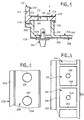
- la figure 1 représente une vue schématique, partielle et en coupe, d'un combiné pour tableaux de bord de véhicules automobiles conforme à la présente invention,
- la figure 2 représente une vue avant du réhaut conforme à la présente invention, voyant enlevé, selon la vue schématisée par la flêche référencée A sur la figure 1, et
- la figure 3 représente une vue similaire du boîtier de combiné conforme à la présente invention, réhaut enlevé.
- FIG. 1 represents a schematic view, partial and in section, of a combined vehicle dashboard according to the present invention,
- FIG. 2 represents a front view of the flange according to the present invention, sight glass removed, according to the view shown diagrammatically by the arrow referenced A in FIG. 1, and
- Figure 3 shows a similar view of the handset housing according to the present invention, flange removed.
On aperçoit sur la figure 1, une vue partielle d'un combiné conforme à la présente invention comprenant au moins un filtre 100, une pièce d'habillage ou réhaut 200 et un boîtier 300.FIG. 1 shows a partial view of a handset in accordance with the present invention comprising at least one
Le boîtier 300 peut faire l'objet de nombreuses variantes de réalisation. De préférence, il est réalisé par moulage d'une pièce en matière plastique.The
Pour l'essentiel, le boîtier 300 comprend une plaque de base généralement plane 302 pourvue sur sa face avant 304 d'une pluralité de toiles 306. Ces toiles 306 s'étendent sensiblement perpendiculairement à la face avant 304 de la plaque de base 302. Les toiles 306 peuvent être adaptées pour supporter tout accessoire approprié.Essentially, the
De préférence, les toiles 306 définissent entre autres, comme représenté sur la figure 3, une pluralité de cheminées 310 destinées chacune à recevoir une source lumineuse 350.Preferably, the
A cet effet, par exemple une plaque de base 302 est munie d'un perçage central 308 en regard de chaque cheminée 310.To this end, for example a
Les lampes 350 peuvent être montées selon toutes techniques connues de l'homme de l'art, de préférence selon un montage du type à baîonnette.The
De préférence, l'alimentation des lampes 350 est réalisée par l'intermédiaire d'un circuit imprimé 360 souple ou rigide, placé sur la face arrière 309 de la plaque de base 302, plus précisément entre cette face arrière 309 et le culot des lampes 350.Preferably, the
On notera à l'examen de la figure 3, que les cheminées 310 précitées recevant les lampes 350 sont formées par un ensemble de toiles 306 orthogonales entre elles.It will be noted on examining FIG. 3 that the
Le circuit imprimé 360 peut être utilisé non seulement pour alimenter les lampes 350 servant de témoins indicateurs, mais également pour transmettre les signaux électriques de commande à des mouvements de type logomètre utilisés par exemple pour indiquer la vitesse de déplacement du véhicule ou servir de compte-tours.The printed
La pièce d'habillage ou réhaut 200 peut également faire l'objet de nombreuses variantes de réalisation. Elle est de préférence réalisée par moulage d'une pièce en matière plastique.The covering piece or
De préférence, le réhaut 200 comprend une jupe périphérique 202 et un voile 204.Preferably, the
La jupe 202 s'étend perpendiculairement à la paroi de base 302. Son contour est défini en fonction de l'esthétique recherchée et de la place disponible au niveau du tableau de bord. Le voile 204 s'étend perpendiculairement à la jupe 202, sur la surface interne 203 de celle-ci.The
Le voile 204 se raccorde de préférence sensiblement à mi-longueur de la jupe 202, ou le cas échéant à proximité de son bord avant 205, tout en étant de préférence formé en retrait de ce bord avant 205.The
Comme cela apparaît à l'examen de la figure 1, la jupe 202 est conçue pour entourer les toiles 306, en étant généralement parallèles à certaines au moins de celles-ci, tandis que le voile 204 est conçu pour reposer contre le bord avant des toiles 306. Le voile 204 est ainsi sensiblement parallèle à la plaque de base 302. Le boîtier, et plus précisément la plaque de base 302, peut être fixé par tous moyens classiques appropriés, de préférence par des vis sur le réhaut 200, plus précisément sur la jupe 202, au niveau du bord arrière 206 de celle-ci.As appears on examining FIG. 1, the
Comme cela apparaît à l'examen des figures 1 et 2, le voile 204 est muni de différents perçages 207 centrés sur les cheminées 310 formées par les toiles 306 du boîtier. Ainsi, les perçages 207 sont placés respectivement en regard d'une lampe 350 formant témoin indicateur.As appears on examining FIGS. 1 and 2, the
Le ou les filtres 100 conformes à la présente invention sont des films généralement de faible épaisseur de l'ordre de 0.1 à 1 mm sérigraphiés collés sur la face avant du voile 204 du réhaut. Plus précisément, de préférence, le ou les filtres 100 sont fixés dans un décrochement 208 formé sur la face avant du voile 204, de sorte que la face avant 102 de chaque filtre affleure la face avant 209 du voile 204.The filter (s) 100 according to the present invention are generally thin films of the order of 0.1 to 1 mm screen printed bonded to the front face of the
Bien entendu, dans le cadre de la présente invention, il peut être prévu plusieurs filtres 100 séparés.Of course, in the context of the present invention, several
Le filtre 100 sérigraphié peut être formé par toute technique classique connue de l'homme de l'art.The screen-printed
A titre d'exemple non limitatif, le filtre 100 conforme à la présente invention peut être réalisé en procédant à deux dépôts successifs d'encre de sérigraphie sur un film de base. Le film de base peut être formé par exemple d'un film de polycarbonate translucide. L'un des dépôts de sérigraphie est de préférence un dépôt d'encre de couleur, tandis que l'autre dépôt effectué par sérigraphie est un dépôt d'encre de couche dépendant de l'aspect désiré opaque configuré selon les symboles recherchés.By way of nonlimiting example, the
La demanderesse a déterminé qu'il était important de prévoir une surface de liaison importante entre la face arrière 104 du filtre 100 et le fond du décrochement 208. En effet, les combinés pour tableaux de bord doivent accepter une plage de température ambiante importante, généralement -30°C à +80°C. Par ailleurs, et en fonction des lampes 350 allumées, les filtres 100 peuvent être soumis à des températures dépassant localement 110°C, cette température n'étant pas homogène sur toute la longueur du filtre 100. Il est par ailleurs important de noter que lorsque conformément à la présente invention, le filtre 100 est collé sur la face avant du réhaut 200, rien ne retient les déformations vers l'avant de ce filtre. Une mauvaise fixation du filtre sur le réhaut serait susceptible de créer des déformations ou effets de bulles locales tout à fait préjudiciables.The Applicant has determined that it is important to provide a large bonding surface between the
Sur ce point, l'utilisation d'une face d'appui formée par le fond du décrochement 208 présentant seulement des perçages localisés 207 de section réduite, s'est avérée très avantageuse.On this point, the use of a bearing face formed by the bottom of the
Le filtre 100 peut être fixé sur le fond du décrochement 208 par tous moyens classiques appropriés. Il s'agit de préférence d'un collage. Ce collage peut être obtenu soit à l'aide d'une colle sérigraphiée, soit à l'aide d'une colle déposée par report. Dans les deux cas, pour éviter un débordement de colle lorsqu'une pression est appliquée sur le filtre 100, la zone d'application de colle sérigraphiée ou déposée par report est prévue en retrait des bords latéraux du filtre 100 et des perçages 207. Par ailleurs, de préférence on évite de placer de la colle en regard des symboles prévus sur le filtre.The
Bien entendu la présente invention n'est pas limitée au mode de réalisation particulier qui vient d'être décrit mais s'étend à toutes variantes conformes aux revendications suivantes.Of course the present invention is not limited to the particular embodiment which has just been described but extends to all variants according to the following claims.
Claims (5)
- A display unit for a motor vehicle dashboard, the display unit being of the type comprising:
a housing (300) housing light sources (308);
at least one filter (100) received in a recess and of thickness substantially equal to the depth of the recess, the filter being provided with symbols placed in register with the light sources (308);
a piece of trim (200) forming a spacer placed in front of the housing (300), in which:
the spacer (200) comprises a peripheral skirt (202) and a mask (204) that extends perpendicularly to the skirt (202) from the inside surface thereof, the mask being adapted to rest against the front face of the housing (300);
through holes (207) are formed in the mask (204), which holes (207) are placed in register firstly with symbols provided on the filter (100) and secondly with light sources carried by the housing (300);
the display unit being characterized by the fact that:
the mask is set back from the front edge (205) of the skirt (202) which faces towards the driver;
the recess (208) is formed in the front face of the mask (204) of the spacer (200); and
the filter (100) is formed by a silk-screen printed film stuck to the bottom of the recess (208) formed in the front face of the mask (204) of the spacer, the front face of the filter (100) being flush with the front face of the mask (204) of the spacer. - A unit according to claim 1, characterized by the fact that the housing (300) essentially comprises a base plate (302) provided on its front face (304) with a plurality of webs (306) that form chimneys (310), each housing a light source (350).
- A unit according to claim 1 or 2, characterized by the fact that each filter (100) is made by silk-screen printed deposits of ink on a translucent base film.
- A unit according to any one of claims 1 to 3, characterized by the fact that each filter (100) is stuck to the front face of the spacer by means of a silk-screen printed adhesive.
- A unit according to any one of claims 1 to 3, characterized by the fact that each filter (100) is stuck to the front face of the spacer (200) by means of adhesive that is deposited by transfer.
Applications Claiming Priority (2)
| Application Number | Priority Date | Filing Date | Title |
|---|---|---|---|
| FR9101831A FR2672853B1 (en) | 1991-02-15 | 1991-02-15 | IMPROVEMENT TO HANDSETS FOR DASHBOARDS OF MOTOR VEHICLES. |
| FR9101831 | 1991-02-15 |
Publications (2)
| Publication Number | Publication Date |
|---|---|
| EP0505221A1 EP0505221A1 (en) | 1992-09-23 |
| EP0505221B1 true EP0505221B1 (en) | 1995-04-05 |
Family
ID=9409767
Family Applications (1)
| Application Number | Title | Priority Date | Filing Date |
|---|---|---|---|
| EP92400383A Expired - Lifetime EP0505221B1 (en) | 1991-02-15 | 1992-02-13 | Improved display-unit for dashboards in automotive vehicles |
Country Status (4)
| Country | Link |
|---|---|
| EP (1) | EP0505221B1 (en) |
| DE (1) | DE69201896T2 (en) |
| ES (1) | ES2071445T3 (en) |
| FR (1) | FR2672853B1 (en) |
Families Citing this family (9)
| Publication number | Priority date | Publication date | Assignee | Title |
|---|---|---|---|---|
| FR2703008B1 (en) * | 1993-03-25 | 1995-06-16 | Jaeger | LOW THICKNESS DASHBOARD, PARTICULARLY FOR MOTOR VEHICLES. |
| FR2703959B1 (en) * | 1993-04-14 | 1995-05-24 | Sagem | Dashboard with high dial support. |
| DE9311962U1 (en) * | 1993-08-11 | 1993-10-28 | Bö-LA Siebdrucktechnik GmbH, 42477 Radevormwald | Labeling film for valve front panels |
| FR2709708B1 (en) * | 1993-09-07 | 1995-11-10 | Sagem | Advanced dashboard. |
| FR2715354B1 (en) * | 1994-01-24 | 1996-04-12 | Jaeger | Dashboard including an improved flange. |
| FR2718394B1 (en) * | 1994-04-11 | 1996-06-28 | Jaeger | Improvements to vehicle dashboards, especially motor vehicles. |
| DE29511962U1 (en) * | 1995-07-25 | 1995-09-28 | Mannesmann Kienzle Gmbh, 78052 Villingen-Schwenningen | Display device for functions and operating states of a motor vehicle |
| GB2319757B (en) * | 1996-11-29 | 1999-02-17 | Delco Electronic Overseas Corp | Instrument cluster |
| FR2759036B1 (en) * | 1997-02-05 | 1999-03-05 | Sagem | REDUCED DEPTH DASHBOARD |
Family Cites Families (4)
| Publication number | Priority date | Publication date | Assignee | Title |
|---|---|---|---|---|
| JPS52115236U (en) * | 1976-02-27 | 1977-09-01 | ||
| DE2942730A1 (en) * | 1979-10-23 | 1981-05-07 | Dr.Ing.H.C. F. Porsche Ag, 7000 Stuttgart | Motor vehicle operating parameter display - has non-reflecting matt foil in front of screen printed symbols |
| GB2098147A (en) * | 1981-05-13 | 1982-11-17 | Ford Motor Co | Instrument panel for a vehicle |
| IT207811Z2 (en) * | 1986-05-23 | 1988-02-15 | Borletti Spa | PANEL INDICATOR OF THE EFFICIENCY OF BODIES OF A VEHICLE |
-
1991
- 1991-02-15 FR FR9101831A patent/FR2672853B1/en not_active Expired - Fee Related
-
1992
- 1992-02-13 EP EP92400383A patent/EP0505221B1/en not_active Expired - Lifetime
- 1992-02-13 DE DE69201896T patent/DE69201896T2/en not_active Expired - Fee Related
- 1992-02-13 ES ES92400383T patent/ES2071445T3/en not_active Expired - Lifetime
Also Published As
| Publication number | Publication date |
|---|---|
| DE69201896D1 (en) | 1995-05-11 |
| DE69201896T2 (en) | 1995-08-31 |
| FR2672853B1 (en) | 1993-06-18 |
| EP0505221A1 (en) | 1992-09-23 |
| FR2672853A1 (en) | 1992-08-21 |
| ES2071445T3 (en) | 1995-06-16 |
Similar Documents
| Publication | Publication Date | Title |
|---|---|---|
| EP0046717B1 (en) | Screen with integrated signalling arrangement for a vehicle and process for its production | |
| EP0505221B1 (en) | Improved display-unit for dashboards in automotive vehicles | |
| FR2860758A1 (en) | Illuminable instrument panel display for vehicle, has light source arranged in central region defined by edges of plate for illuminating indicia formed in plate by transmitting light through inner edge of plate | |
| EP0676307A1 (en) | Improvements in dashboards for vehicles, especially motor vehicles | |
| FR2767753A1 (en) | Comprehensive analogue and digital automobile instrument display | |
| EP0715988A1 (en) | Tail-light for vehicle | |
| EP3083315B1 (en) | Display device intented notably for a motor vehicle | |
| EP4093627B1 (en) | Motor vehicle instrument cluster with reflective panel | |
| FR2871415A1 (en) | DASHBOARD A DISPLAY HOUSING OF DISPLAY AND DISPLAY FOR DASHBOARD | |
| FR2760414A1 (en) | Motor vehicle instrument panel, that gives clearer information | |
| EP0420708A1 (en) | Driver's information display system at the interior of a car | |
| EP0499549B1 (en) | Dashboard for automotive vehicles | |
| EP0676313B1 (en) | Dashboard for automotive vehicle with lighting device | |
| FR3083182A1 (en) | LUMINOUS MODULE FOR THE LIGHTING OF THE INTERIOR OF A MOTOR VEHICLE COMPRISING A TOUCH INTERFACE | |
| FR2721396A1 (en) | Pointer instrument with window and light source esp. for motor vehicle | |
| EP0511887B1 (en) | Display device for automotive vehicles | |
| EP0610105A1 (en) | Pointer instrument | |
| FR2707224A1 (en) | Dashboard without optical duct. | |
| WO2023180639A1 (en) | Projected display device for a motor vehicle dashboard | |
| EP0910519B1 (en) | Indicator for motor vehicles | |
| FR3121972A1 (en) | PANEL WITH INTEGRATED INTERNAL LIGHTING | |
| FR2710978A1 (en) | Indicator assembly with needle, needle therefor and application to motor vehicle dashboards | |
| FR2731958A1 (en) | Instrument panel construction for motor vehicle | |
| FR2779860A1 (en) | BI-MATERIAL LIGHT BLOCK INDICATOR | |
| FR2583558A1 (en) | Device for illuminating a display plate |
Legal Events
| Date | Code | Title | Description |
|---|---|---|---|
| PUAI | Public reference made under article 153(3) epc to a published international application that has entered the european phase |
Free format text: ORIGINAL CODE: 0009012 |
|
| AK | Designated contracting states |
Kind code of ref document: A1 Designated state(s): DE ES GB IT |
|
| 17P | Request for examination filed |
Effective date: 19921102 |
|
| 17Q | First examination report despatched |
Effective date: 19921216 |
|
| GRAA | (expected) grant |
Free format text: ORIGINAL CODE: 0009210 |
|
| AK | Designated contracting states |
Kind code of ref document: B1 Designated state(s): DE ES GB IT |
|
| GBT | Gb: translation of ep patent filed (gb section 77(6)(a)/1977) |
Effective date: 19950403 |
|
| REF | Corresponds to: |
Ref document number: 69201896 Country of ref document: DE Date of ref document: 19950511 |
|
| REG | Reference to a national code |
Ref country code: ES Ref legal event code: FG2A Ref document number: 2071445 Country of ref document: ES Kind code of ref document: T3 |
|
| ITF | It: translation for a ep patent filed | ||
| PLBE | No opposition filed within time limit |
Free format text: ORIGINAL CODE: 0009261 |
|
| STAA | Information on the status of an ep patent application or granted ep patent |
Free format text: STATUS: NO OPPOSITION FILED WITHIN TIME LIMIT |
|
| 26N | No opposition filed | ||
| PGFP | Annual fee paid to national office [announced via postgrant information from national office to epo] |
Ref country code: GB Payment date: 19990219 Year of fee payment: 8 Ref country code: ES Payment date: 19990219 Year of fee payment: 8 |
|
| PGFP | Annual fee paid to national office [announced via postgrant information from national office to epo] |
Ref country code: DE Payment date: 19990317 Year of fee payment: 8 |
|
| PG25 | Lapsed in a contracting state [announced via postgrant information from national office to epo] |
Ref country code: GB Free format text: LAPSE BECAUSE OF NON-PAYMENT OF DUE FEES Effective date: 20000213 |
|
| PG25 | Lapsed in a contracting state [announced via postgrant information from national office to epo] |
Ref country code: ES Free format text: LAPSE BECAUSE OF NON-PAYMENT OF DUE FEES Effective date: 20000214 |
|
| GBPC | Gb: european patent ceased through non-payment of renewal fee |
Effective date: 20000213 |
|
| PG25 | Lapsed in a contracting state [announced via postgrant information from national office to epo] |
Ref country code: DE Free format text: LAPSE BECAUSE OF NON-PAYMENT OF DUE FEES Effective date: 20001201 |
|
| REG | Reference to a national code |
Ref country code: ES Ref legal event code: FD2A Effective date: 20010910 |
|
| PG25 | Lapsed in a contracting state [announced via postgrant information from national office to epo] |
Ref country code: IT Free format text: LAPSE BECAUSE OF NON-PAYMENT OF DUE FEES Effective date: 20050213 |