EP0504879B1 - Flüssigkeitsstrahlaufzeichnungskopf und Flüssigkeitsstrahlaufzeichnungsgerät, welches diesen aufweist - Google Patents
Flüssigkeitsstrahlaufzeichnungskopf und Flüssigkeitsstrahlaufzeichnungsgerät, welches diesen aufweist Download PDFInfo
- Publication number
- EP0504879B1 EP0504879B1 EP92104786A EP92104786A EP0504879B1 EP 0504879 B1 EP0504879 B1 EP 0504879B1 EP 92104786 A EP92104786 A EP 92104786A EP 92104786 A EP92104786 A EP 92104786A EP 0504879 B1 EP0504879 B1 EP 0504879B1
- Authority
- EP
- European Patent Office
- Prior art keywords
- liquid
- ink
- recording head
- bubble
- throat
- Prior art date
- Legal status (The legal status is an assumption and is not a legal conclusion. Google has not performed a legal analysis and makes no representation as to the accuracy of the status listed.)
- Expired - Lifetime
Links
- 239000007788 liquid Substances 0.000 title claims abstract description 143
- 238000011144 upstream manufacturing Methods 0.000 claims description 47
- 239000000463 material Substances 0.000 claims description 22
- 230000008033 biological extinction Effects 0.000 claims description 4
- 230000035939 shock Effects 0.000 description 82
- 230000005499 meniscus Effects 0.000 description 24
- 230000002829 reductive effect Effects 0.000 description 18
- 230000003139 buffering effect Effects 0.000 description 16
- 230000001105 regulatory effect Effects 0.000 description 15
- 230000000694 effects Effects 0.000 description 11
- 230000033001 locomotion Effects 0.000 description 11
- 238000004519 manufacturing process Methods 0.000 description 8
- 230000008859 change Effects 0.000 description 7
- 230000007423 decrease Effects 0.000 description 7
- FNYLWPVRPXGIIP-UHFFFAOYSA-N Triamterene Chemical compound NC1=NC2=NC(N)=NC(N)=C2N=C1C1=CC=CC=C1 FNYLWPVRPXGIIP-UHFFFAOYSA-N 0.000 description 6
- 238000010438 heat treatment Methods 0.000 description 6
- 238000000034 method Methods 0.000 description 6
- 238000007639 printing Methods 0.000 description 6
- 238000011156 evaluation Methods 0.000 description 5
- 230000006872 improvement Effects 0.000 description 5
- 238000012360 testing method Methods 0.000 description 5
- 238000009835 boiling Methods 0.000 description 4
- 238000004140 cleaning Methods 0.000 description 4
- 238000010586 diagram Methods 0.000 description 4
- 238000009826 distribution Methods 0.000 description 4
- 230000009467 reduction Effects 0.000 description 4
- 230000004044 response Effects 0.000 description 4
- 239000011358 absorbing material Substances 0.000 description 3
- 230000008901 benefit Effects 0.000 description 3
- 230000003247 decreasing effect Effects 0.000 description 3
- 230000008021 deposition Effects 0.000 description 3
- 230000006866 deterioration Effects 0.000 description 3
- 230000002542 deteriorative effect Effects 0.000 description 3
- 230000000670 limiting effect Effects 0.000 description 3
- 230000008569 process Effects 0.000 description 3
- 230000000644 propagated effect Effects 0.000 description 3
- 230000000087 stabilizing effect Effects 0.000 description 3
- 230000001629 suppression Effects 0.000 description 3
- 230000005540 biological transmission Effects 0.000 description 2
- 230000015572 biosynthetic process Effects 0.000 description 2
- 238000012937 correction Methods 0.000 description 2
- 238000011161 development Methods 0.000 description 2
- 238000011835 investigation Methods 0.000 description 2
- 229920002492 poly(sulfone) Polymers 0.000 description 2
- 238000011084 recovery Methods 0.000 description 2
- 239000011347 resin Substances 0.000 description 2
- 229920005989 resin Polymers 0.000 description 2
- 229920001090 Polyaminopropyl biguanide Polymers 0.000 description 1
- 239000004695 Polyether sulfone Substances 0.000 description 1
- 239000004721 Polyphenylene oxide Substances 0.000 description 1
- 239000004743 Polypropylene Substances 0.000 description 1
- 230000004308 accommodation Effects 0.000 description 1
- 230000009471 action Effects 0.000 description 1
- 230000001154 acute effect Effects 0.000 description 1
- 229910052782 aluminium Inorganic materials 0.000 description 1
- XAGFODPZIPBFFR-UHFFFAOYSA-N aluminium Chemical compound [Al] XAGFODPZIPBFFR-UHFFFAOYSA-N 0.000 description 1
- 239000007767 bonding agent Substances 0.000 description 1
- 229920005549 butyl rubber Polymers 0.000 description 1
- 239000003086 colorant Substances 0.000 description 1
- 238000004891 communication Methods 0.000 description 1
- 230000001276 controlling effect Effects 0.000 description 1
- 230000001934 delay Effects 0.000 description 1
- 230000001419 dependent effect Effects 0.000 description 1
- 230000001066 destructive effect Effects 0.000 description 1
- 230000008020 evaporation Effects 0.000 description 1
- 238000001704 evaporation Methods 0.000 description 1
- 238000002474 experimental method Methods 0.000 description 1
- 230000010365 information processing Effects 0.000 description 1
- 238000007689 inspection Methods 0.000 description 1
- 239000011344 liquid material Substances 0.000 description 1
- 229910052751 metal Inorganic materials 0.000 description 1
- 239000002184 metal Substances 0.000 description 1
- 239000000203 mixture Substances 0.000 description 1
- 238000012986 modification Methods 0.000 description 1
- 230000004048 modification Effects 0.000 description 1
- 238000000465 moulding Methods 0.000 description 1
- 230000006911 nucleation Effects 0.000 description 1
- 238000010899 nucleation Methods 0.000 description 1
- 238000005192 partition Methods 0.000 description 1
- 230000000149 penetrating effect Effects 0.000 description 1
- 239000000049 pigment Substances 0.000 description 1
- 229920006393 polyether sulfone Polymers 0.000 description 1
- 229920006380 polyphenylene oxide Polymers 0.000 description 1
- -1 polypropylene Polymers 0.000 description 1
- 229920001155 polypropylene Polymers 0.000 description 1
- 238000003825 pressing Methods 0.000 description 1
- 230000001737 promoting effect Effects 0.000 description 1
- 230000001902 propagating effect Effects 0.000 description 1
- 230000000717 retained effect Effects 0.000 description 1
- 229920002379 silicone rubber Polymers 0.000 description 1
- 239000004945 silicone rubber Substances 0.000 description 1
- 238000004088 simulation Methods 0.000 description 1
- 239000007787 solid Substances 0.000 description 1
- 239000011343 solid material Substances 0.000 description 1
- 239000002904 solvent Substances 0.000 description 1
- 230000006641 stabilisation Effects 0.000 description 1
- 238000011105 stabilization Methods 0.000 description 1
- 239000000758 substrate Substances 0.000 description 1
- 230000001360 synchronised effect Effects 0.000 description 1
- 230000001052 transient effect Effects 0.000 description 1
- 239000012780 transparent material Substances 0.000 description 1
- 230000003313 weakening effect Effects 0.000 description 1
Images


Classifications
-
- B—PERFORMING OPERATIONS; TRANSPORTING
- B41—PRINTING; LINING MACHINES; TYPEWRITERS; STAMPS
- B41J—TYPEWRITERS; SELECTIVE PRINTING MECHANISMS, i.e. MECHANISMS PRINTING OTHERWISE THAN FROM A FORME; CORRECTION OF TYPOGRAPHICAL ERRORS
- B41J2/00—Typewriters or selective printing mechanisms characterised by the printing or marking process for which they are designed
- B41J2/005—Typewriters or selective printing mechanisms characterised by the printing or marking process for which they are designed characterised by bringing liquid or particles selectively into contact with a printing material
- B41J2/01—Ink jet
- B41J2/135—Nozzles
- B41J2/14—Structure thereof only for on-demand ink jet heads
- B41J2/14016—Structure of bubble jet print heads
- B41J2/14032—Structure of the pressure chamber
- B41J2/1404—Geometrical characteristics
-
- B—PERFORMING OPERATIONS; TRANSPORTING
- B41—PRINTING; LINING MACHINES; TYPEWRITERS; STAMPS
- B41J—TYPEWRITERS; SELECTIVE PRINTING MECHANISMS, i.e. MECHANISMS PRINTING OTHERWISE THAN FROM A FORME; CORRECTION OF TYPOGRAPHICAL ERRORS
- B41J2/00—Typewriters or selective printing mechanisms characterised by the printing or marking process for which they are designed
- B41J2/005—Typewriters or selective printing mechanisms characterised by the printing or marking process for which they are designed characterised by bringing liquid or particles selectively into contact with a printing material
- B41J2/01—Ink jet
- B41J2/135—Nozzles
- B41J2/14—Structure thereof only for on-demand ink jet heads
- B41J2002/14379—Edge shooter
-
- B—PERFORMING OPERATIONS; TRANSPORTING
- B41—PRINTING; LINING MACHINES; TYPEWRITERS; STAMPS
- B41J—TYPEWRITERS; SELECTIVE PRINTING MECHANISMS, i.e. MECHANISMS PRINTING OTHERWISE THAN FROM A FORME; CORRECTION OF TYPOGRAPHICAL ERRORS
- B41J2/00—Typewriters or selective printing mechanisms characterised by the printing or marking process for which they are designed
- B41J2/005—Typewriters or selective printing mechanisms characterised by the printing or marking process for which they are designed characterised by bringing liquid or particles selectively into contact with a printing material
- B41J2/01—Ink jet
- B41J2/135—Nozzles
- B41J2/14—Structure thereof only for on-demand ink jet heads
- B41J2002/14387—Front shooter
-
- B—PERFORMING OPERATIONS; TRANSPORTING
- B41—PRINTING; LINING MACHINES; TYPEWRITERS; STAMPS
- B41J—TYPEWRITERS; SELECTIVE PRINTING MECHANISMS, i.e. MECHANISMS PRINTING OTHERWISE THAN FROM A FORME; CORRECTION OF TYPOGRAPHICAL ERRORS
- B41J2202/00—Embodiments of or processes related to ink-jet or thermal heads
- B41J2202/01—Embodiments of or processes related to ink-jet heads
- B41J2202/11—Embodiments of or processes related to ink-jet heads characterised by specific geometrical characteristics
Definitions
- the present invention relates to a liquid jet recording technique, more particularly to a liquid jet recording head, a liquid jet recording apparatus having the same and a liquid jet cartridge having the same, usable with office equipment such as printer, copying machine or facsimile machine. More particularly, it relates to a liquid jet recording head having an improved liquid passage (nozzle) from the standpoint of high quality and high speed printing.
- Ink jet recorders in which the ink is ejected are known as a non-impact type recording device.
- the means for ejecting the ink there are piezoelectric element for mechanically deforming the ink to reduce the volume of the liquid passage to eject the ink, and heat generating resistor which is effective to apply heat to the ink in a liquid passage to produce an instantaneous state change thereof adjacent the heat generating portion, so that the ejection pressure is imparted to the ink.
- JP-A-5559975, JP-A-5559976 and JP-A-5559977 and US-A-4,330,787 have made a proposal for the purpose of improving the ejection efficiency, the ejection response property, the ejection stability, the long period continuing printing and high speed recording or the like.
- the recent demand for the high speed and high resolution with further stability has required a further improvement. More particularly, the further improvement is desired in the ejection efficiency, a higher speed liquid ejection and higher stability.
- the ejecting ink is generally divided into three droplets.
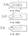
- the first is a main droplet constituting the main portion of the dot formed on the recording material, which is designated by a reference D1 in Figures 22 and 23.
- the second is a so-called satellite which is torn from the trail of the main droplet and which follows the main droplet in the form of a rod through the orifice.
- the satellite may be in some cases in the form of plural droplets and reaches the recording material to form a print dot.
- the satellite is designated by a reference D2 in Figures 22 and 23.
- the satellite droplet reaches the recording material substantially simultaneously with the main droplet, and therefore, is overlaid on the dot of the main droplet, thus constituting a significant part of the print dot.
- the third is the microdroplet designated in Figures 22 and 23 by a reference D3.
- the microdroplet is produced through the following process. When the bubble created by the applied heat is collapsed, the upstream ink and the downstream ink collide with the result of a shock wave of pressure starting from the collision point 2 in Figures 22 and 23, which wave gives a momentum to ink in the neighborhood of the meniscus. The momentum ejects the ink out.
- the microdroplet D3 delays from the main droplet D1 and the satellite droplet D2 and the amount of ink thereof is smaller than the main droplet D1 and the satellite D2.
- the printed dot provided by the main and satellite droplets and the printed dot by the microdroplet are deviated on the recording medium, or they constitute discrete dots, with the result of degraded print quality.
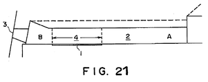
- Figure 21 shows a schematic longitudinal section of the nozzle of the Comparison Example indicated by the solid lines in Figure 21. It comprises a heat generating resistor 1 on a side of an ink passage 2, and the heat generated thereby acts on the ink filled in the ink passage 2. Then, the ink on the heat generating resistor 1 (heat acting portion 4) instantaneously changes its state (bubble creation), and a part of the ink passage is ejected through the ejection outlet 3 onto the recording material. The bubble created by the heat from the heat generating resistor 1 is collapsed and extinguished with the stop of the power supply to the heat generating resistor. Then, the ink passage 2 is then filled with the ink (the ink refilling).
- the pressure wave propagates toward the ejection outlet (downstream, direction B), and simultaneously it propagates toward the ink supply side (upstream, direction A) in the form of a backward wave. If the backward wave toward the upstream is strong, it may reach the other nozzle or nozzles through a common liquid chamber which is disposed upstream of the nozzles and functions to supply the ink commonly to the nozzles. Then, there occurs a liability that the ejection in the other nozzle or nozzles are influenced.
- a liquid jet recording head comprising the features of the pre-characterizing clause of claim 1 belongs to the state of the art.
- An example of this known liquid jet recording head is shown in figure 21 and comprises the wall surface indicated by the dashed line in figure 21.
- Figure 1 is a sectional view of a recording head according to an embodiment of the present invention.
- Figure 2 is a sectional view of a recording head in which the shock wave is controlled, according to an embodiment of the present invention.
- Figure 3 shows a pressure distribution in the recording head according to an embodiment of the present invention.
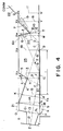
- Figure 4 is a diagram illustrating the structure of the recording head according to an embodiment of the present invention.
- Figure 5 is a cross-sectional view of the recording head according to an embodiment of the present invention.
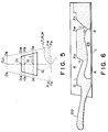
- Figure 6 illustrates the ink ejection in the recording head according to an embodiment of the present invention.
- Figure 7 is a perspective view of a multi-nozzle structure of a recording head according to an embodiment of the present invention.
- Figure 8 is a sectional view of a recording head according to another embodiment of the present invention.
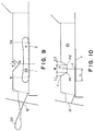
- Figure 9 is a sectional view of a recording head according to a further embodiment of the present invention, in which the recording head is provided with a throat.
- Figure 10 is a sectional view of a recording head according to a further embodiment of the present invention.
- Figure 11 shows results of tests of the nozzle according to an embodiment of the present invention in which the cross-sectional area of the throat is changed.
- Figure 12 shows results of tests of a nozzle according to the present invention in which the throat position is changed.
- Figure 13 shows results of tests of a nozzle according to the present invention in which the throat width W is changed.
- Figure 14 shows results of test of the nozzles of the present invention in which the forward cross-sectional area changing portion is changed.
- Figure 15 shows results of tests of a nozzle of the present invention in which the backward cross-sectional area changing portion is changed.
- Figure 16 is a sectional view of a recording head according to a further embodiment of the present invention.
- Figure 17 is a front view of a nozzle according to a further embodiment of the present invention.
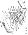
- Figure 18 is an exploded perspective view of an example of a liquid jet cartridge according to an embodiment of the present invention.
- Figure 19 is a perspective view thereof.
- Figure 20 shows a recording apparatus to which the present invention is applicable.
- Figure 21 is a sectional view of conventional (chain lines) and Comparison Example (solid lines) nozzles.
- Figure 22 illustrates the liquid ejection in the recording head according to the Comparison Example.
- Figure 23 illustrates the liquid ejection in side views corresponding to Fig. 22.
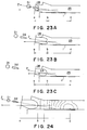
- Figure 24 illustrates the pressure distribution in the recording head according to the Comparison Example.
- FIG. 1 there is shown a longitudinal sectional view of the liquid passage of an ink jet recording head according to an embodiment of the present invention.
- the control of the liquid droplet ejecting direction will first be described.
- the inventors have investigated the difference in the ejection directions of the microdroplets and the main droplets, and have found the following. Since the ink constituting the main droplet is present adjacent the orifice (a-b) immediately before the bubble creation, as shown in Figure 23, the ejecting direction of the main droplet is largely influenced by the configuration of the orifice (OR) portion, and therefore, the direction is substantially along the central axis Z. On the other hand, the microdroplet D3 is produced, at the time of the bubble collapse, the meniscus (position b) which is at the most retracted position.
- the most retracted position appears upon the extinction of the bubble, wherein the delay due to the propagation of the shock wave can be neglected.
- the ink is not contact with the orifice portion (OR), and therefore, the configuration of the orifice portion (OR) is not much influential to the microdroplet ejection direction. Since the microdroplet is produced by the shock wave starting at the bubble collapse position (position d) hits the meniscus at the position b, the direction of the microdroplet is largely influenced by the direction of propagation of the shock wave.
- Figure 24 shows how the shock wave propagates, and is a isobar diagram showing the pressure distribution immediately after the collapse of the bubble.
- the isobaric lines of the shock wave starting from the bubble collapse point is first influenced by the configuration of the ink service at which the body of the ink collide, and away from the collapse or colliding position (position c), they are influenced by the configuration of the liquid passage wall.
- the boundary condition here is that the isobaric lines of the pressure wave are perpendicular to the wall of the liquid passage. In other words, the vector of the velocity of the ink flow is zero along the wall surface on the wall of the nozzle wall.
- the isobaric lines of the shock wave in the neighborhood of the position c become perpendicular to the nozzle central axis between the positions c and d. Because of the divergence of the passage between the positions c and d, the upper part of the isobaric lines slightly change, but at the position b (retracted meniscus position), the isobaric lines are substantially the same as those characterized between the positions c and d.
- the flow of the ink is in the direction of the maximum change direction of the pressure distribution.
- the momentum of the microdroplet produced at the meniscus position b is directed perpendicular to the tangential lines of the meniscus and of the isobaric line at the position b, that is, along the central axis Z of the nozzle between the positions b and c.
- the direction of the ejection is different from the direction of the main droplet in the case where the direction of the central axis of the orifice is different from the central axis of the nozzle adjacent the bubble collapse point.
- the printed dot by the main droplet and the satellite droplet, and the dot printed by the microdroplet are significantly deviated on the recording material, with the result of remarkable print quality deterioration.
- Figure 2 is a longitudinal sectional view of the liquid passage in which the ejection direction of the liquid droplet is controlled.
- the ejection outlet is defined by O1-O2-P2-P1-O1
- an external opening of the ejection outlet is defined by O2-P2.
- a heater extends in the direction perpendicular to the sheet of the drawing.
- the main droplet and the satellite droplet are ejected by the driving of the heat generating resistor, that is, the heater substantially along the axis Z.
- the structure for adjusting the nozzle axis behind the orifice is constituted by the passage defined by a line LH and a line MJ in the Figure.
- a bisector of the angle formed between the lines LH and MJ is substantially along the orifice central axis. This is not inevitable, but is finely adjusted for the individual cases, since the print quality is dependent on the other structure of the nozzle, the nature of the liquid, the relative speed between the nozzle unit and the recording material or the like.
- Figure 3 is an isobar diagram immediately after the bubble collapsed, obtained by simulation using computer, and it will be understood from this diagram that lines perpendicular to the isobar lines is substantially toward the orifice.
- the isobar lines are inclined as compared with the case of the conventional liquid passage, so that the line perpendicular to the isobar line contacting the meniscus 24 is directed through the orifice.
- Figure 4 shows in detail the structure of the liquid passage of Figure 1.
- Figure 5 is a cross-sectional view of various longitudinal position of the liquid passage perpendicular to the axis of the liquid passage provided with the heat generating resistor 1.
- Figure 6 shows the maximum expansion of the bubble in the passage of Figure 4. The description thereof are for this embodiment, and thus not particularly limit the present invention.
- the heat generating resistor 1 side is taken as a bottom side. However, this is not limiting.
- the ejection side of the liquid passage 25 will be described.
- the various portions of the liquid passage 25 have configuration of symmetric trapezoid configuration, so that the width in the cross-section increases symmetrically from the top side toward the heat generating resistor 1.
- the symmetric center extends between the centers of the bottom and top sides of the trapezoid, and a set of the lines connecting the central points is a central plane of the liquid passage, and the central surface of the liquid passage is as shown in Figure 4.
- FIG 7 is a perspective view showing the interval configuration of the liquid passage.
- the ejection outlet reference center line Z passes through the center of the external opening of the ejection outlet and the center of internal opening O1-O2.
- the shock wave correcting portion 4 is constituted by a wall surface HL.
- a cross-sectional area of the passage is considered which is taken on a plane perpendicular to the ejection outlet central axis Z (or the surface area YU having the electrothermal transducer element with electrode (not shown) and the heat generating resistor and preferably with the protection layer).
- the inclined surface HL is effective to monotonously increase the cross-sectional area from a region HJ (shock wave regulating portion 9 which will be described hereinafter) in the heat generating resistor portion or the heat acting portion KABX B X X H toward the ejection outlet (LN or LM).
- the shock wave correcting zone is defined by plane HJ, an inclined surface HL in a liquid passage region including a part of the surface area YU and a plane LN which is perpendicular to the heat generating resistor surface Y and which passes through a line L which is an ejection side end of the inclined surface (preferably a plane LM which is parallel with the ejection side surface O1-P1 and passing through a line L).
- This zone contains the maximum retracted position of the meniscus when the meniscus retracted most (substantially simultaneous with the collapse of the bubble).
- the maximum retracted position of the meniscus is substantially determined by the size of the bubble produced on the basis of the resistance of the heat generating resistor 1 and the electric energy supplied thereto, and the liquid passage upstream of the ejection outlet. This can be easily determined because the proper cross-sectional area of the liquid passage, the liquid and the driving pulse are selected in a limited range in the usual ink jet recording head.
- shock wave front after passing through the shock wave regulating portion 9 is corrected to be substantially perpendicular to the reference axis Z.
- the isobar lines crosses with the wall of the passage perpendicularly. Since the surface HL is inclined relative to the surface YU, the inclination of the shock wave is corrected, as shown in Figure 3.
- the shock wave is sufficiently corrected by the shock wave correcting portion.
- the shock wave correcting portion has a large length in the region downstream of the heat generating resistor, but if the downstream length is too long, the ink ejection speed lowers with the result of image quality deterioration.
- the correction is easy in the region near the bubble collapse position.
- the shock wave correcting portion starts at the position above the heat generating resistor 1 (heat acting portion).
- the corrected shock wave hits the center of the meniscus when it is retracted most, and therefore, the microdroplet ejecting direction can be made equal to the ejection direction of the main droplet and the satellite droplet.
- the shock wave correcting portion 4 may be constituted by the portion HK only, but in order to stabilize the ejection direction, the longer correcting portion 4 is desirable.
- the shock wave is further corrected from a point K to the point L, and therefore, the traveling direction of the shock wave in the neighborhood of the plane LN is satisfactorily corrected to the substantially the same as the ejection direction of the main droplet.
- the maximum retracted position of the meniscus is in a space defined by L, M and N in this embodiment. This is preferable because the wavefront corrected to be perpendicular to the difference central axis Z can stabilize the ejection direction of the microdroplet.
- the maximum retracted position of the meniscus may be placed in a space defined by a plane KYk passing through a line K and parallel with the plane LM, a plane AYk and a plane KA, the ejection direction is controlled as compared with the conventional recording head.
- the plane HJ as the correcting portion starting plane is within a zone facing to the heat generating resistor 1 producing the shock wave.
- the plane HJ is nearer to the ejection side than the bubble collapse point 2.
- the solid line wall of the liquid passage 25 is indicated such that the cross-sectional area of the liquid passage is constant along the axis Z from the connecting portion OP with the ejection outlet to the plane LM.
- the correction of the shock wave is mainly determined by the wave front of the shock wave resulting in the microdroplet, and therefore, the shock wave subsequent to that produced by the initial collision is not influential to the microdroplet.
- the configuration of the subsequent wave in the plane OL is not important.
- the provision of the extension 21 is effective to provide the desired state of collision even if the maximum retracted position of the meniscus changes more or less due to the change in the ambient condition or another.
- the retracted position of the meniscus varies to some extent.
- the cross-sectional area of the liquid passage reduces from the region 14 having the inclined surface LM toward the heat generating resistor 1, more particularly toward the region 15 and region 9, and therefore, the direction of the liquid movement toward the buffer chamber as a result of the collapse of the bubble is limited, and therefore, the retraction of the meniscus is more stabilized than in the prior art.
- the regions indicated by R and S are given the configurations shown in Figure 8.
- the inclined surface LH of Figure 4 has additional advantage, more particularly, the stabilization of the ejecting force for assuredly and efficiently eject the main droplet and the satellite droplet in the ejecting direction Z is accomplished. This is because the region 9 which is the starting line of the inclined surface LH is disposed at the ejection outlet side in the neighborhood of a central portion 1C of the heat generating resistor 1 along the liquid path, and therefore, the ejecting force by the bubble toward the ejection side can be efficiently and effectively applied to the ejection side liquid.
- the side OAOB has a length of 25.5 ⁇ m; the side PAPB has a length of 58.5 ⁇ m; the height LN is 70 ⁇ m; and angle ⁇ formed between the reference central axis Z of the ejection part and the surface Y having the heat generating resistor is 10 degrees; an angle ⁇ formed between an extension of the inclined surface LH and the surface Y having the heat generating resistor at point C is 20 degrees (an angle ⁇ in Figure 8 is 70 degrees); a height HJ is approximately 40 ⁇ m; a length AB of the heat generating resistor 1 is approximately 150 ⁇ m; a distance between points N and J is 82 ⁇ m; a distance between points A and J is 55 ⁇ m; a distance between points O and L is 26 ⁇ m; a distance between point N and P is 38 ⁇ m; a distance between points 1C and J is 17 ⁇ m.
- the angular different between the main droplet and the microdroplet is not more than several degrees, and therefore, even if the clearance between the ejection outlet of the recording head and the recording material is approximately 1 mm, the microdroplet deposition point is substantially within the feathering region of the main droplet. Otherwise, the microdroplet is continuous with the main droplet deposition area, and therefore, the formed image is clear and sharp.
- An intersection G between the central axis line Z and the above-described plane YU is on the heat acting surface, that is, the top surface of the heat generating resistor and is substantially at the center 1C of the heat generating resistor 1, but it is disposed closer to the liquid chamber COMM from the center 1C.
- the shock wave correcting portion may be defined, for example, as a zone having a shock wave regulating portion HJ disposed in the heat acting zone, a monotonously increasing cross-sectional area zone in which the cross-sectional area of the liquid passage monotonously increases along the reference central line from the regulating zone to the liquid ejecting zone. It is not necessarily concerned with the position of the bubble collapse point 2, but in order to provide the most advantageous effects, it is preferably disposed in the ejection side from the bubble collapse point.
- An angle ⁇ formed between the inclined surface 4 and the surface YU is preferably larger than the angle ⁇ between the central axis of the ejection outlet and the surface YU by not less than 5 degrees, further preferably, not less than 10 degrees, since then the length of the liquid passage can be reduced without losing the advantageous effect described hereinbefore.
- a length of the inclined surface 4 is not less than 1, preferably, not less than 1.5 times the height HJ of the region 9. From the standpoint of stabilizing the meniscus formation, it is preferably larger than twice.
- the bubble collapse portion 2 is in a space HCY defined by an extension of the inclined surface 4 and the heat acting surface.
- the bubble collapse point 2 is not contained in the shock wave correcting zone; the correcting passage has a length JN larger than a distance between the bubble collapse point 2 and the regulating portion 9; and the most retracted meniscus after the liquid ejection in the normal state is in the correcting zone. This is because the ejecting energy is efficiently used for the movement of the liquid, and simultaneously, the length of the entire liquid passage can be reduced.
- the cross-sectional area of the shock wave correcting region is preferably symmetrical, and in addition from the standpoint of easy motion of the liquid toward the ejection outlet, the width of the surface having the heat generating resistor is larger than the width of the side faced thereto. Then, as shown in Figure 4, the pressure is concentrated to the top side of the symmetrical trapezoid to increase the buffering effect to reduce the pressure resulting from the shock wave.
- control of bubble creation and collapse and a member for controlling the shock wave resulting at the time of bubble collapse to increase the refilling property and to control the production of the microdroplet.
- the inventors' investigations in these respects have revealed the following.
- the liquid passage cross-sectional area is increased to reduce the liquid flow resistance so that the flow rate of the ink from the upstream side (A) is increased.
- the liquid passage cross-sectional area is simply increased, the size of the bubble created increases with the result of increase of the ink quantity to be supplied by the refilling action, and therefore, the refilling property is not improved.
- the problem can be solved by increasing the ink passage and providing a local minimum point of the cross-sectional area at least at one position effective to control the bubble created in the heat acting zone of the ink passage and to control the shock wave or the like.
- the local minimum position may be called throat or shock wave regulating portion.
- the size of the bubble created is so regulated that the unnecessary backward motion of the ink toward the upstream is suppressed, so that the shorter refilling time is required.
- the amount of liquid ejection and the speed thereof are significantly stabilized. This is because the improvement in the balance in the flow resistance and the mass between the ejection outlet and the throat. Also, it has been confirmed that the service life of the heater is improved.
- the structure is effective to reduce the shock wave propagation to the ejection outlet, and therefore, the production of the microdroplet is reduced. The structure for accomplishing this will be described in detail.
- Figure 9 is a longitudinal sectional view of a further embodiment.
- Figure 9 is a central longitudinal sectional view when the bubble is created.
- a reference numeral 1 designates a heat generating resistor
- D0 designates the ink which is going to be ejected through the ejection outlet 12 by the bubble creation
- 2 designates the bubble collapse point at which the bubble 23 finally collapses or disappears.
- the ink mass and the flow resistance is smaller in the ejection side of the heat generating resistor 1 than in the upstream side thereof.
- the motion of the ink at the time of the bubble collapse is influenced thereby, and therefore, the bubble collapse point is upstream of the center of the heater length.
- the local minimum of the cross-sectional area of the ink passage is disposed above the heat generating resistor on the ejection side of the bubble collapse point 2.
- the provision of the local minimum HJ of the cross-sectional area is effective to divide the energy resulting from the bubble creation into the ejection side or downstream side and the upstream side. Further, by inclining the surface toward the ejection outlet as shown in the Figure, the bubble expanding energy toward the top can be deflected toward the ejection outlet, thus increasing the ink ejection speed.
- An angle ⁇ constituting partly the local minimum H is preferably large to some extent from the standpoint of directing the bubble expansion energy to the ejection outlet, that is, from the standpoint of the upward component of the bubble expansion energy more to the ejection outlet side than toward the upstream.
- an angle ⁇ is preferably small.
- ⁇ > ⁇ is preferable.
- the ink passage cross-sectional area monotonously increases from the local minimum HJ toward the ejection outlet. During the bubble collapsing period, the ink flows toward the collapse position from the upstream and downstream of the ejection heater with the reduction of the volume of the bubble 23.
- the local minimum is in the ejection side zone from the bubble collapse point, and therefore, during the bubble collapse period, the ejection side surface LH ( Figure 4) of the local minimum point gives the flow resistance against the ink flow from the ejection outlet side. Therefore, the amount of meniscus retraction after the ink ejection can be reduced, and therefore, the amount of ink required for filling the passage up to the front side of the nozzle, can be reduced.
- the ink flowing to the bubble collapse point from the ejection outlet side during the collapsing period of the bubble passes through the local minimum cross-sectional area, and produces eddy or turbulent current at the upstream side of the local minimum portion (in the neighborhood of the surface XXH in Figure 4).
- This is effective to suppress the upward motion of the ink, so that the refilling property is further increased, and in addition the eddy or turbulent flows function to weaken the impact force at the time of the bubble collapse, and therefore, the service life of the heat generating resistor can be increased.
- the cross-sectional area increasing rate in the area downstream (ejection side) of the local minimum is larger than that in the upstream side. Therefore, the angles ⁇ and ⁇ satisfy ⁇ > ⁇ .
- the local minimum position is preferably above the heater.
- the configuration of the local minimum providing portion above the heater may have an apex, as shown in Figure 9, or may be trapezoidal as shown in Figure 10.
- the throat position is defined as a center H on the top surface of the trapezoid (minimum cross-sectional area position).
- the configuration of the throat (minimum cross-sectional area position) is further investigated.
- Figure 10 is a sectional view of a nozzle including an external opening 12 of the ejection outlet, a heat generating resistor 1 and an ink passage 25 which is connected with other nozzles through a common liquid chamber.
- nozzle length is 350 ⁇ m; a nozzle cross-sectional area is 3200 ⁇ m 2 ; an area of an external opening of the ejection outlet is 900 ⁇ m 2 ; a heater length is 150 ⁇ m; a cross-sectional area S of the opening in the throat HJ is 200 - 3000 ⁇ m 2 ; throat position L (a distance from the ejection side end of the ejection heater to the point J) is 0 - 250 ⁇ m; the width W of the throat is 0 - 150 ⁇ m; a length L1 of the front sectional area changing portion (the shock wave correcting portion described hereinbefore) is 0 - 150 ⁇ m; a length L2 of a backward sectional area changing portion (shock wave reducing portion) is 0 - 150 ⁇ m.
- the above dimensions given in ranges mean that the dimensions are changed in the range.
- the nozzles numbers 1 - 5 commonly have the throat position length L of 75 ⁇ m, the throat length W of 30 ⁇ m, the front area changing portion length L1 of 30 ⁇ m, and the rear area changing portion length L2 of 30 ⁇ m, and the throat area was changed 200 - 3000 ⁇ m 2 .
- the nozzles numbers 3, 6 - 9 commonly had the throat area S of 1600 ⁇ m 2 , the throat length W of 30 ⁇ m, the front area changing portion length L1 of 30 ⁇ m, the rear area changing portion length L2 of 30 ⁇ m, and the throat position distance L was changed between 0 - 150 ⁇ m.
- the nozzles numbers 10 - 13 commonly had the throat area S of 1600 ⁇ m 2 , the throat position distance L of 75 ⁇ m, the front area changing portion length L1 of 30 ⁇ m, and the rear area changing portion length L2 of 30 ⁇ m, and the throat length W was changed between 0 - 150 ⁇ m.
- the nozzles numbers 14 - 17 commonly had the throat area S of 1600 ⁇ m 2 , the throat position distance L of 75 ⁇ m, the throat length W of 30 ⁇ m, and the rear area changing portion length L2 of 30 ⁇ m, and the front area changing portion length L1 was changed between 0 - 120 ⁇ m.
- the nozzles numbers 18 - 21 commonly had the throat area S of 1600 ⁇ m 2 , the throat position distance L of 75 ⁇ m, and throat length W of 30 ⁇ m, and the front area changing portion length L2 of 30 ⁇ m, and the rear area changing length L1 was changed between 0 - 120 ⁇ m.
- the nozzles number 22 and 23 did not have the throat as in the conventional nozzle (solid lines in Figure 21), and the cross-sectional area was simply increased (Figure 21, broken lines) as Comparison Examples.
- the 23 recording heads were manufactured, operated and evaluated from the standpoint of the maximum bubble volume and the ink refilling time required.
- Figure 11 shows the evaluations of the nozzles numbers 1 - 5 in which the throat area was changed in the range between 200 - 3000 ⁇ m 2 .
- the throat area S2 With the reduction of the throat area S2, the maximum bubble volume is decreased. Below 400 ⁇ m 2 of the throat area S2, the refilling period is increased, probably because of the increase of the resistance against flow by the local minimum of the flow area. Therefore, the tolerable range of the throat area is 400 - 2800 ⁇ m 2 .
- the throat area is preferably not less than 40 % and not more than 80 % of the cross-sectional area at the bubble collapse position, practically.
- the throat area is preferably out of contact with the created bubble.
- the nozzle without the throat having a large flow resistance in the nozzle requires a large refilling time as between that of No. 4 nozzle and that of No. 5 nozzle.
- the nozzle having the expanded flow passage showed substantially the same refilling as the nozzle No. 1.
- Figure 12 shows the evaluations of the nozzles Nos. 6 - 9 in which the throat position distance L is changed in the range between 0 - 150 ⁇ m.
- the throat position distance L is changed in the range between 0 - 150 ⁇ m.
- Figure 13 shows the evaluations of the nozzles 10 - 13 in which the throat length was changed in the range between 0 - 150 ⁇ m.
- the throat length W is not less than 100 ⁇ m, the refilling time increases, the reason for this is considered to be increase of the flow resistance.
- the optimum range of the throat length W is 0 - 90 ⁇ m, and as a ratio relative to the heat generating resistor, it is preferably 0 - 3/4.
- Figure 14 shows evaluations of nozzles No. 14 - 17 in which the front area changing portion length L1 is changed in the range between 0 - 150 ⁇ m.
- the maximum volume of the bubble decreases.
- the refilling time increases.
- the optimum range of the front area changing portion length is 0 - 90 ⁇ m, and as the ratio to the heat generating resistor, it is preferably 0 - 3/5.
- Figure 15 shows evaluations of the nozzles Nos. 18 - 21 in which the rear area changing portion length L2 is changed in the range between 0 - 150 ⁇ m.
- the maximum volume of the bubble decreases.
- the refilling time increases, probably because of the increase of the flow resistance by the area changing portion.
- the optimum range of the rear area changing portion length is 0 - 90 ⁇ m, and as a ratio to the length of the heat generating portion, it is preferably 0 - 3/5.
- the throat is preferably such that it has a as small as possible angle as seen from the bubble collapse point.
- the throat is defined as the most ejection side portion of the throat. In other words, the area of the throat is preferably as small as possible.
- the flow resistance of the throat increases with the decrease of the area thereof, and therefore, there is a proper range.
- the cross-sectional area of the opening of the throat is preferably not less than 1/8 and not more than 7/8 to the maximum cross-sectional area of the flow passage in the nozzle.
- the throat position is preferably disposed between the bubble collapse point and a position one fifth of the heater length or more upstream of the ejection side edge of the heater. Further preferably, it is disposed adjacent the center between the ejection side edge of the heater and the bubble collapse point.
- the front area changing portion may have shorter length as shown in Figure 16 in order to reduce the flow resistance.
- the surfaces LH, HXX may be curved.
- the sectional area is a longitudinal sectional view taken along a plane including the symmetric axis.
- the area reducing portion formed at the top surface of the ink passage is capable of adjusting the pressure produced by the bubble creation and to adjust the shock wave produced by the bubble collapse, without impeding the flow of the ink along the heat generating resistor.
- one throat portion is formed above the heat generating resistor.
- a plurality of such throats may be provided depending on the required adjustments of the flow resistance and the wave propagation at the bubble collapse.
- Figure 17 shows an example in which projections 26 and 27 are provided between L and H and N and J in order to further reduce the shock wave propagated to the ejection outlet.
- Figure 17 is a front view of the nozzle as seen from the ejection outlet side.
- the throat was provided by an integral portion of the wall constituting the ink passage, but this is not limiting, and may be in the form of a separate member or members.
- the throat constituting portion is formed on the surface faced to the ejection heater surface, but it or they may be formed on one or more of the lateral wall surfaces.
- the shock wave regulating portion 9 in the form of a throat can be defined as an end of the above-described shock wave correcting portion or as the transient region from the monotonously reducing cross-sectional area portion to the monotonously increasing region toward the ejection outlet of the passage.
- the cross-sectional area of the opening of the shock wave regulating portion 9 is preferably larger than the cross-sectional area of the opening of the backward liquid regulating portion 10 which will be described hereinafter. Also preferably, it is disposed before the extension of the central axis of the ejecting outlet reaches the heat acting surface.
- the cross-sectional configuration of the shock wave regulating portion is preferably symmetrical.
- the cross-sectional configuration in a plane perpendicular to the liquid passage is such that the width is increasing toward the heat generating resistor. More particularly, the symmetric trapezoidal configuration is preferable as shown in Figure 4, since then the shock wave buffering effect is promoted.
- the rear area changing portion (shock wave reducing portion 5) in the form of a wall partly constituting the throat may be defined as a zone above the heat acting surface (heat acting zone), which is effective to attenuate the shock wave of the bubble collapse or to introduce it in the direction opposite from the ejection outlet. It is preferably a monotonously reducing area zone.
- the preferable conditions for the shock wave reducing portion 5 other than those described hereinbefore is that it comprises a portion faced to an ejection side region of the center 1C of the length of the heat generating portion along the liquid passage, more particularly, the portion is not less than 50 % (further preferably not less than 70 %). It is also preferable that the entirety thereof is faced to the heat acting portion and the ejecting portion.
- the projection thereof to the heat generating surface formed by the normal line to the surface X X H of the reducing portion 5 is in the buffering chamber JT which will be described hereinafter.
- These conditions are effective not only to regulate the shock wave but also to use the pressure resulting from the creation of the bubble 23 to suppress the expansion thereof toward the liquid chamber. The combination of all of the above conditions is most preferable.
- an angle ⁇ is 30 degrees
- the inclined surface X X H is such that the end point X X of the inclined surface X X H is at an intersection between the surface X and the line perpendicular to the surface area YU and passing through the center 1C of the resistor.
- the cross-sectional area has the configuration preferably as described in conjunction with the shock wave regulating portion 9.
- the position of the throat is disposed to resist the upstream expansion of the bubble, in other words, it is disposed upstream of the heat generating resistor (bubble creating position). However, if it is too far, the bubble expansion suppressing effect is reduced.
- the cross-sectional area of the opening of the additional throat is preferably small since then the bubble expansion suppression effect is stronger. However, if it is too small, the refilling property is deteriorated.
- the throat is effective to reduce the required ink supply quantity by suppressing the expansion of the bubble, but the flow resistance is locally increased, and therefore, the ink supply speed becomes lower as compared with the structure without the throat.
- the ink supply speed can be made high enough.
- the additional throat is disposed upstream of the position corresponding to the heat generating resistor (ejection heater) 1.
- the configuration thereof is such that the cross-sectional area decreases in a region 7 from a plane 22 of the upstream common liquid chamber COMM through Q-X-X V to the minimum area portion I, and the cross-sectional area again increases in a zone 6 from the minimum portion toward the ejection outlet (I-X W ).
- the region 6 has an angle ⁇ shown in the Figure.
- the direction of the surface is faced to the ejection heater (bubble creating position).
- the region 7 has an angle ⁇ as shown in the Figure, such that an acute angle is formed between the direction along the region 7 and the surface area YU having the ejection heater.
- the bubble 23 is produced from the ejection heater position. With the expansion of the bubble, the pressure is propagated to the ink in the passage 25, so that a recording droplet is ejected through the outside opening of the ejection outlet 12, and simultaneously, the ink is pushed back toward upstream in the nozzle. At this time, in the region adjacent the surface 6 in the throat, reversed flows of the ink occurs along the surface X W -I in the direction toward the surface having the ejection heater, as indicated by arrow 20. By these flows of the ink, the upstream expansion of the bubble is suppressed.
- the cross-sectional opening area of the throat T-I is smaller than that of the other portions of the liquid passage, and therefore, the pressure is high adjacent the throat (8), by which the upstream expansion of the bubble is suppressed.
- the turbulent or eddy flow 19 of the ink is produced in the upstream region 7 and adjacent the region defined by X V -X, so that the flow is produced in the ink convection zone and on the surface 7 in the direction from X V to I.
- the surface X V -X is effective to stabilize the turbulence 19.
- the ink flow toward the liquid chamber produced in the bubble creation is stopped and then the ink supply is started, if the throat is not provided in the nozzle.
- the ink is quickly supplied to the ejection heater surface along the surface 7 from the turbulent region 19, and therefore, the refilling time can be reduced. This is because of the provision of the throat means faced to the ejection heater, and the throat has such a surface as to direct the turbulent flow to the ejection heater.
- the height of the wall 22 of the common chamber (COOM) from the point X has a larger height, and therefore, the ink can be supplied along the top surface from the liquid chamber, irrespective of the backward wave of the ink produced by the bubble creation.
- the throat means When the throat means is formed upstream of the portion faced to the ejection heater, the flow (arrow 20) effective to suppress the upstream expansion of the bubble is not produced. In addition, the ink supply to the ejection heater is impeded by the throat means, and therefore, it is difficult to reduce the refilling time.
- the provision of the throat is effective to efficiently propagate the bubble creation pressure for the ejection of the liquid, and therefore, the upstream length of the nozzle upstream from the heat generating resistor can be shortened to permit ejection of the required size droplet.
- the upstream side beyond the heat generating layer is preferably short, because the ink can be supplied quickly. Therefore, the throat is effective to reduce the length of the nozzle to reduce the ink supply period, thus allowing the high speed recording.
- the pressure during the bubble creation is high at the top portion away from the ejection heater than in the portion close to the heat generating resistor.
- the bottom surface having the ejection heater particularly requiring the ink supply has a larger width than the top side, and is free from a part constituting the throat, and therefore, the ink can be supplied smoothly. This is also effective to reduce the refilling time.
- the walls 6 and 7 for constituting the upstream side and the downstream side of the throat are preferably symmetric in a sectional view perpendicular to the liquid passage. It is also preferable that the cross-sectional area monotonously changes by the walls 6 and 7 from the standpoint of smooth supply of the ink.
- An extension D of the surface 7 reaches the non-heat generating-resistor portion of the surface area YU having the heat generating resistor. Particularly, it is closer to the liquid chamber than the bubble collapse point of the heat generating resistor. Furthermore, the effect is enhanced if it is adjacent the extension C of the shock wave regulating portion, and is liquid chamber side of the extension C.
- the upstream throat (back wave regulating portion 10) preferably has a height not more than one half the height of the liquid passage. The number thereof is preferably only one between the heat generating resistor and the liquid chamber connecting portion, from the standpoint of reducing the length of the total liquid passage, but this is not limiting in connection with the other structures.
- the buffering chamber functions to buffer the propagation of the upward pressure particularly the upward pressure to the liquid common chamber COMM and simultaneously to utilize the buffering effect to the suppression of the bubble expansion toward the upstream. It at least comprises a liquid outlet region which is disposed on the ejection outlet side from the center of the heat acting portion and in which the buffering surface is directed toward upstream in the heat acting surface side of the buffering chamber, and a liquid inlet region which is disposed on the upstream side of the center of the heat acting zone and in which the buffering surface is directed to the center of the heat acting portion.
- the structure of the buffering chamber is defined by the above-described two throats. In this case, the bubble collapse point is between the two throats.
- the projections of the walls 5 and 6 constituting the throats onto the surface area YU having the heat generating resistor are within the buffering chamber. Almost all of the projection of the surface 6 in the surface direction is projected on the surface area YU at the ejection outlet side of the throat 9. These are the preferable conditions for the buffering chamber structure.
- the ink is moved toward the rear or toward the ejection heater with the expansion of the bubble.
- the flow of the ink not related to the ink ejection is enclosed between the throats (H-X X -X W -I), that is, in the buffering chamber.
- the ink in the buffering chamber does not have a releasing portion during the bubble creation, and therefore, is forced to expand in the direction H-X X with the result of flow along X W -I (arrow 20).
- the flow is effective to suppress the created bubble, and thus preventing the unnecessary expansion of the bubble, so that the refilling speed is further increased.
- the energy resulting from the bubble creation can be concentrated to the ejection outlet side, and simultaneously, the backward flow of the ink (backward wave) can be reduced, and also, the time required for the refilling can be reduced.
- the inclined surface X W -I of the rear throat is preferably upstream of the center of the heat acting zone in the direction of the passage (ink passage on the ejection heater: A-B-X B -K). Further preferably, it is upstream of the heat acting zone.
- the angle of the surface X W -I is practically 0 ⁇ ⁇ ⁇ 90 degrees, preferably 5 ⁇ ⁇ ⁇ 60 degrees, further preferably 5 ⁇ ⁇ ⁇ 45 degrees, yet further preferably 5 ⁇ ⁇ ⁇ 30 degrees.
- the angle H-X X preferably satisfies ⁇ ⁇ ⁇ ⁇ 90 degrees.
- the pressure, particularly the backward wave which is not necessary for the liquid ejection and the shock wave can be reduced in the buffering chamber.
- the flow of the ink to the bubble collapse position occurs along the surface I-X V to produce turbulent flow toward the ejection heater surface, so that the propagation of the shock wave during the bubble collapse to the ejection heater can be reduced, and therefore, the service life of the heater can be increased.
- Figures 18, 19 and 20 illustrate an ink jet unit IJU, an ink jet heat IJH, an ink container IT, an ink jet cartridge IJC and a main assembly IJRA of an ink jet recording apparatus, according to an embodiment of the present invention, and relations among them.
- the structures of the respective elements will be described in the following.
- the ink jet cartridge IJC in this embodiment has a relatively large ink accommodation space, and an end portion of the ink jet unit IJU is slightly projected from the front side surface of the ink container IT.
- the ink jet cartridge IJC is mountable at correct position on the carriage HC of the ink jet recording apparatus main assembly IJRA by proper positioning means and with electric contacts, which will be described in detail hereinafter. It is, in this embodiment, a small type head detachably mountable on the carriage AC.
- the structures disclosed in Figures 18 and 19 contain various features, which will first be described generally.
- the ink jet unit IJU is of a bubble jet recording type using electrothermal transducers which generate thermal energy, in response to electric signals, to produce film boiling of the ink.
- the unit comprises a heater board 100 having electrothermal transducers (ejection heaters) arranged in a line on an Si substrate and electric lead lines made of aluminum or the like to supply electric power thereto.
- the electrothermal transducer and the electric leads are formed by a film forming process.
- a wiring board 200 is associated with the heater board 100 and includes wiring corresponding to the wiring of the heater board 200 (connected by the wire bonding technique, for example) and pads 201 disposed at an end of the wiring to receive electric signals from the main assembly of the recording apparatus.
- a top plate 1300 is provided with grooves which define partition walls for separating adjacent ink passages and a common liquid chamber for accommodating the ink to be supplied to the respective ink passages.
- the top plate 1300 is formed integrally with an ink jet opening 1500 for receiving the ink supplied from the ink container IT and directing the ink to the common chamber, and also with an orifice plate 400 having the plurality of ejection outlets corresponding to the ink passages.
- the material of the integral mold is preferably polysulfone, but may be another molding resin material.
- a supporting member 300 is made of metal, for example, and functions to support a backside of the wiring board 200 in a plane, and constitutes a bottom plate of the ink jet unit IJU.
- a confining spring 500 is in the form of "M" having a central portion urging to the common chamber with a light pressure, and a clamp 501 urges concentratedly with a line pressure to a part of the liquid passage, preferably the part in the neighborhood of the ejection outlets.
- the confining spring 500 has legs for clamping the heater board 100 and the top plate 1300 by penetrating through the openings 3121 of the supporting plate 300 and engaging the back surface of the supporting plate 307.
- the heater board 100 and the top plate 1300 are clamped by the concentrated urging force by the legs and the clamp 501 of the spring 500.
- the wiring board 200 is mounted on the supporting member 300 by bonding agent or the like.
- the ink supply member 600 is molded, and therefore, it is produced at low cost with high positional accuracy.
- the cantilevered structure of the conduit 1600 assures the press-contact between the conduit 1600 and the ink inlet 1500 even if the ink supply member 600 is mass-produced.
- the ink container comprises a main body 1000, an ink absorbing material and a cover member 1100.
- the ink absorbing material 700 is inserted into the main body 1000 from the side opposite from the unit (IJU) mounting side, and thereafter, the cover member 1100 seals the main body.
- the ink absorbing material 900 is thus disposed in the main body 1000.
- the ink jet cartridge IJC After the ink jet cartridge IJC is assembled, the ink is supplied from the inside of the cartridge to the chamber in the ink supply member through a supply opening 936, the whole 320 of the supporting member 305 and an inlet formed in the backside of the ink supply member 600. From the chamber of the ink supply member 600, the ink is supplied to the common chamber through the outlet, supply pipe and an ink inlet 1500 formed in the top plate 1300.
- the connecting portion for the ink communication is sealed by silicone rubber or butyl rubber or the like to assure the hermetical seal.
- the top plate 1300 is made of resin material having resistivity to the ink, such as polysulfone, polyether sulfone, polyphenylene oxide, polypropylene. It is integrally molded in a mold together with an orifice plate portion 400.
- the integral part comprises the ink supply member 600, the top plate 1300, the orifice plate 400 and parts integral therewith, and the ink container body 1000. Therefore, the accuracy in the assembling is improved, and is convenient in the mass-production. The number of parts is smaller than inconventional device, so that the good performance can be assured.
- FIG 20 is a perspective view of an ink jet recording apparatus IJRA in which the present invention is used.
- a lead screw 5005 rotates by way of a drive transmission gears 5011 and 5009 by the forward and backward rotation of a driving motor 5013.
- the lead screw 5005 has a helical groove 5004 with which a pin (not shown) of the carriage HC is engaged, by which the carriage HC is reciprocable in directions a and b.
- a sheet confining plate 5002 confines the sheet on the platen 5000 over the carriage movement range.
- Home position detecting means 5007 and 5008 are in the form of a photocoupler to detect presence of a lever 5006 of the carriage, in response to which the rotational direction of the motor 5013 is switched.
- a supporting member 5016 supports the front side surface of the recording head to a capping member 5022 for capping the recording head.
- Sucking means 5015 functions to suck the recording head through the opening 5023 of the cap so as to recover the recording head.
- a cleaning blade 5017 is moved toward front and rear by a moving member 5019. They are supported on the supporting frame 5018 of the main assembly of the apparatus.
- the blade may be in another form, more particularly, a known cleaning blade.
- a lever 5021 is effective to start the sucking recovery operation and is moved with the movement of a cam 5020 engaging the carriage, and the driving force from the driving motor is controlled by known transmitting means such as clutch or the like.
- the capping, cleaning and sucking operations can be performed when the carriage is at the home position by the lead screw 5005, in this embodiment.
- the present invention is usable in another type of system wherein such operations are effected at different timing.
- the individual structures are advantageous, and in addition, the combination thereof is further preferable.
- the liquid passage structure leads to an ink jet recording head and an ink jet recording apparatus having a high ejection efficiency without satellite printing, so that a high quality printing is possible.
- the productivity is remarkably improved in the case of mass-production to provide a high density multi-orifice type head and apparatus.
- a wall portion is deliberately disposed across the liquid passage of the satellite droplet to prevent or impede the satellite droplet from ejecting out of the recording head, so that the satellite droplet printing is prevented or reduced.
- the present invention is particularly suitably usable in a ink jet recording head and recording apparatus developed by Canon Kabushiki Kaisha, Japan. This is because, the high density of the picture element, and the high resolution of the recording are possible.
- the principle is applicable to a so-called on-demand type recording system and a continuous type recording system, particularly however, it is suitable for the on-demand type because the principle is such that at least one driving signal is applied to an electrothermal transducer disposed on a liquid (ink) retaining sheet or liquid passage, the driving signal being enough to provide such a quick temperature rise beyond a departure from nucleation boiling point, by which the thermal energy is provide by the electrothermal transducer to produce film boiling on the heating portion of the recording head, whereby a bubble can be formed in the liquid (ink) corresponding to each of the driving signals.
- the liquid (ink) is ejected through an ejection outlet to produce at least one droplet.
- the driving signal is preferably in the form of a pulse, because the development and collapse of the bubble can be effected instantaneously, and therefore, the liquid (ink) is ejected with quick response.
- the driving signal in the form of the pulse is preferably such as disclosed in US-A-4,463,359 and US-A-4,345,262.
- the temperature increasing rate of the heating surface is preferably such as disclosed US-A-4,313,124.
- the structure of the recording head may be as shown in US-A-4,558,333 and US-A-4,459,600 wherein the heating portion is disposed at a bent portion in addition to the structure of the combination of the ejection outlet, liquid passage and the electrothermal transducer as disclosed in the above-mentioned patents.
- the present invention is applicable to the structure disclosed in JP-A-59123670 wherein a common slit is used as the ejection outlet for plural electrothermal transducers, and to the structure disclosed in JP-A-59138461 wherein an opening for absorbing pressure wave of the thermal energy is formed corresponding to the ejecting portion. This is because, the present invention is effective to perform the recording operation with certainty and at high efficiency irrespective of the type of the recording head.
- the present invention is effectively applicable to a so-called full-line type recording head having a length corresponding to the maximum recording width.
- a recording head may comprise a single recording head and a plural recording head combined to cover the entire width.
- the present invention is applicable to a serial type recording head wherein the recording head is fixed on the main assembly, to a replaceable chip type recording head which is connected electrically with the main apparatus and can be supplied with the ink by being mounted in the main assembly, or to a cartridge type recording head having an integral ink container.
- the recovery means and the auxiliary means for the preliminary operation are preferable, because they can further stabilize the effect of the present invention.
- the recording head mountable it may be a single corresponding to a single color ink, or may be plural corresponding to the plurality of ink materials having different recording color or density.
- the present invention is effectively applicable to an apparatus having at least one of a monochromatic mode mainly with black and a multi-color with different color ink materials and a full-color mode by the mixture of the colors which may be an integrally formed recording unit or a combination of plural recording heads.
- the ink has been liquid. It may be, however, an ink material solidified at the room temperature or below and liquefied at the room temperature. Since in the ink jet recording system, the ink is controlled within the temperature not less than 30 °C and not more than 70 °C to stabilize the viscosity of the ink to provide the stabilized ejection, in usual recording apparatus of this type, the ink is such that it is liquid within the temperature range when the recording signal is applied. In addition, the temperature rise due to the thermal energy is positively prevented by consuming it for the state change of the ink from the solid state to the liquid state, or the ink material is solidified when it is left unused to prevent the evaporation of the ink.
- the ink may be liquefied, and the liquefied ink may be ejected.
- the ink may start to be solidified at the time when it reaches the recording material.
- the present invention is applicable to such an ink material as is liquefied by the application of the thermal energy.
- Such an ink material may be retained as a liquid or solid material on through holes or recesses formed in a porous sheet as disclosed in JP-A 5456847 and JP-A-6071260. The sheet is faced to the electrothermal transducers.
- the most effective one for the ink materials described above is the film boiling system.
- the ink jet recording apparatus may be used as an output terminal of an information processing apparatus such as computer or the like, a copying apparatus combined with an image reader or the like, or a facsimile machine having information sending and receiving functions.
- an information processing apparatus such as computer or the like
- a copying apparatus combined with an image reader or the like or a facsimile machine having information sending and receiving functions.
- the propagation of the shock wave during the bubble collapse is controlled so that the image quality is improved without deteriorating the liquid ejecting force or speed.
- the size of the bubble is limited, so that the unnecessary backward movement of the ink toward the upstream is suppressed with the advantage of shorter refilling period.
- the quantity of ejection or the ejecting speed are significantly stabilized. Since the shock at the time of bubble collapse is eased, and therefore, the service life of the heater is improved. Additionally, the shock wave produced by the collapse of the bubble is eased, and therefore, the production of the microdroplet attributable to the shock wave is reduced.
- the bubble collapse point can be determined as follows, for example.
- the wall opposite from the base plate is made of transparent material such as polysulfonic material.
- the recording head is illuminated by stroboscopic light source which is synchronized with the bubble collapse timing, and the inside of the passage is observed through stereoscopic microscope. In such observation, the pigment or dye component is removed from the ink since otherwise the observation is difficult.
- Such components are usually dissolved in the solvent, and therefore, do not function as the nucleus of the bubble creation or collapse. Accordingly, the removal does not substantially affect the determination of the collapse point.
- the change of the viscosity of the ink by the removal is very slight, and therefore, does not substantially affect the determination of the bubble collapse point.
- the collapse point is observed trough a surface parallel to the base.
- the same method can be used to determine it by observation through a surface perpendicular thereto.
- the recording head has a structure in which the observation is difficult, a proper part of the wall or walls may be removed or may be replaced with a transparent wall. It will be possible to use non-destructive inspection using X-rays or sonic wave.
Landscapes
- Physics & Mathematics (AREA)
- Geometry (AREA)
- Particle Formation And Scattering Control In Inkjet Printers (AREA)
- Ink Jet (AREA)
- Recording Measured Values (AREA)
Claims (13)
- Flüssigkeitsstrahlaufzeichnungskopf mit folgenden Bauteilen:
einem Flüssigkeitsausstoßauslaß (12), der eine Mittellinie (Z) hat,
einem Flüssigkeitkanal (25), der mit dem Ausstoßauslaß (12) verbunden ist;
einem Flächenbereich (YU), der den Flüssigkeitskanal (25) definiert und sich in Richtung auf den Ausstoßauslaß (12) erstreckt;
einem Wärmeerzeugungswiderstand (1) zur Zufuhr von Wärme auf die Flüssigkeit an einem Heizwirkabschnitt (KABXB) des Flüssigkeitskanals (25), um eine Blase (23) in dem Flüssigkeitskanal (25) zu erzeugen, so daß die Flüssigkeit durch den Ausstoßauslaß (12) ausgestoßen wird, wobei der Wärmeerzeugungswiderstand (1) in dem Flächenbereich (YU) des Flüssigkeitskanals (25) angeordnet ist;
und wobei eine Wandfläche (HL) weiter den Flüssigkeitskanal (25) definiert und dem Flächenbereich (YU) gegenüberliegt;
dadurch gekennzeichnet, daß
die Wandfläche (HL) gegenüber dem Flächenbereich (YU) so geneigt ist, daß ein Zwischenbereich zwischen dem Flächenbereich (YU) und der Wandfläche (HL) stetig von einem Bereich (HJ) in dem Heizwirkabschnitt (KABXB) zu dem Ausstoßauslaß (12) ansteigt, wodurch die Querschnittsfläche des Flüssigkeitskanals (25) entlang der geneigten Wandfläche (HL) ansteigt und dadurch, daß die Mittellinie (Z) den Flächenbereich (YU) schneidet. - Aufzeichnungskopf nach Anspruch 1, dadurch gekennzeichnet, daß der Flüssigkeitskanal (25) mit einem Hals (9) in dem Heizwirkabschnitt (KABXB) versehen ist, um ein lokales Minimum der Querschnittsfläche des Flüssigkeitskanals (25) zu schaffen.
- Aufzeichnungskopf nach Anspruch 2, dadurch gekennzeichnet, daß der Flüssigkeitskanal (25) weiter mit einem zweiten Hals (10) versehen ist, der stromaufwärts des Heizwirkabschnitts (KABXB) bezüglich einer Strömungsrichtung der Flüssigkeit angeordnet ist.
- Aufzeichnungskopf nach einem der Ansprüche 1 bis 3, dadurch gekennzeichnet, daß die Wandfläche (HL) näher an dem Ausstoßauslaß (12) als eine Position (2) angeordnet ist, an der die Blase (23) zerfällt.
- Aufzeichnungskopf nach einem der Ansprüche 1 bis 4, dadurch gekennzeichnet, daß ein Winkel (θ), der zwischen der Wandfläche (HL) und dem Flächenbereich (YU) gebildet ist, um nicht weniger als 5 Grad größer als ein Winkel (δ) ist, der zwischen der Mittellinie (Z) des Ausstoßauslasses (12) und dem Flächenbereich (YU) gebildet ist.
- Aufzeichnungskopf nach Anspruch 2, dadurch gekennzeichnet, daß eine Länge der Wandfläche (HL) länger als eine Höhe des Halses (9) ist.
- Aufzeichnungskopf nach einem der Ansprüche 1 bis 6, dadurch gekennzeichnet, daß der Flüssigkeitkanal (25) einen trapezförmigen Querschnitt hat.
- Aufzeichnungskopf nach Anspruch 2, dadurch gekennzeichnet, daß der Hals (9) eine Querschnittsfläche mit 400 - 2800 µm2 hat.
- Aufzeichnungskopf nach Anspruch 2, dadurch gekennzeichnet, daß der Hals (9) eine Querschnittsfläche hat, die 1/8 bis 7/8 Mal der maximalen Querschnittsfläche des Flüssigkeitskanals (25) ist.
- Aufzeichnungskopf nach Anspruch 1, dadurch gekennzeichnet, daß der stetige Anstieg an einem Punkt beginnt, der näher an dem Flüssigkeitsausstoßauslaß (12) als eine Position ist, an der die Blase zerfällt.
- Aufzeichnungskopf nach Anspruch 1, dadurch gekennzeichnet, daß eine Position des Zerfalls der Blase zwischen einer Verlängerung (LC) der Wandfläche (HL) entlang dem Flächenbereich (YU) und dem Flächenbereich (YU) liegt.
- Flüssigkeitsstrahlaufzeichnungsgerät mit einem Aufzeichnungskopf (IJH) nach einem der Ansprüche 1 bis 11 und einer Aufzeichnungsmaterialfördereinrichtung (5000).
- Flüssigkeitsstrahlcartridge (IJC) mit einem Aufzeichnungskopf (IJH) nach einem der Ansprüche 1 bis 11 und einem Flüssigkeitsbehälter (IT), der Flüssigkeit enthält, die dem Aufzeichnungskopf zuzuführen ist.
Applications Claiming Priority (6)
| Application Number | Priority Date | Filing Date | Title |
|---|---|---|---|
| JP5745691 | 1991-03-20 | ||
| JP5745991A JP3049665B2 (ja) | 1991-03-20 | 1991-03-20 | 液体噴射記録ヘッドおよび該記録ヘッドを用いた記録装置 |
| JP57456/91 | 1991-03-20 | ||
| JP57458/91 | 1991-03-20 | ||
| JP5745891 | 1991-03-20 | ||
| JP57459/91 | 1991-03-20 |
Publications (2)
| Publication Number | Publication Date |
|---|---|
| EP0504879A1 EP0504879A1 (de) | 1992-09-23 |
| EP0504879B1 true EP0504879B1 (de) | 1996-10-16 |
Family
ID=27296263
Family Applications (1)
| Application Number | Title | Priority Date | Filing Date |
|---|---|---|---|
| EP92104786A Expired - Lifetime EP0504879B1 (de) | 1991-03-20 | 1992-03-19 | Flüssigkeitsstrahlaufzeichnungskopf und Flüssigkeitsstrahlaufzeichnungsgerät, welches diesen aufweist |
Country Status (5)
| Country | Link |
|---|---|
| US (1) | US6022100A (de) |
| EP (1) | EP0504879B1 (de) |
| AT (1) | ATE144192T1 (de) |
| DE (1) | DE69214489T2 (de) |
| ES (1) | ES2092588T3 (de) |
Families Citing this family (11)
| Publication number | Priority date | Publication date | Assignee | Title |
|---|---|---|---|---|
| CA2108304C (en) * | 1992-10-15 | 1999-08-10 | Hiroyuki Ishinaga | Ink jet recording apparatus |
| AU4092296A (en) | 1995-01-13 | 1996-08-08 | Canon Kabushiki Kaisha | Liquid ejecting head, liquid ejecting device and liquid ejecting method |
| SG79917A1 (en) * | 1995-04-26 | 2001-04-17 | Canon Kk | Liquid ejecting method with movable member |
| US5821962A (en) * | 1995-06-02 | 1998-10-13 | Canon Kabushiki Kaisha | Liquid ejection apparatus and method |
| US5751317A (en) * | 1996-04-15 | 1998-05-12 | Xerox Corporation | Thermal ink-jet printhead with an optimized fluid flow channel in each ejector |
| JPH1024584A (ja) | 1996-07-12 | 1998-01-27 | Canon Inc | 液体吐出ヘッドカートリッジおよび液体吐出装置 |
| EP0873871A3 (de) * | 1997-03-27 | 1999-08-18 | Xerox Corporation | Für visköse Tinten geeigneter Druckkopf für das thermische Tintenstrahldrucken |
| US20020118253A1 (en) * | 2000-03-21 | 2002-08-29 | Nec Corporation | Ink jet head having improved pressure chamber and its manufacturing method |
| JP5750753B2 (ja) * | 2011-01-11 | 2015-07-22 | セイコーエプソン株式会社 | 液体噴射ヘッド及び液体噴射装置 |
| JP5668482B2 (ja) | 2011-01-13 | 2015-02-12 | セイコーエプソン株式会社 | 液体噴射ヘッド及び液体噴射装置 |
| JP5901149B2 (ja) | 2011-06-01 | 2016-04-06 | キヤノン株式会社 | 液体吐出ヘッドおよびその製造方法 |
Family Cites Families (24)
| Publication number | Priority date | Publication date | Assignee | Title |
|---|---|---|---|---|
| CA1127227A (en) * | 1977-10-03 | 1982-07-06 | Ichiro Endo | Liquid jet recording process and apparatus therefor |
| JPS5936879B2 (ja) * | 1977-10-14 | 1984-09-06 | キヤノン株式会社 | 熱転写記録用媒体 |
| US4296421A (en) * | 1978-10-26 | 1981-10-20 | Canon Kabushiki Kaisha | Ink jet recording device using thermal propulsion and mechanical pressure changes |
| JPS5559975A (en) * | 1978-10-31 | 1980-05-06 | Canon Inc | Liquid jet recorder |
| JPS5559977A (en) * | 1978-10-31 | 1980-05-06 | Canon Inc | Liquid injection recorder |
| US4330787A (en) * | 1978-10-31 | 1982-05-18 | Canon Kabushiki Kaisha | Liquid jet recording device |
| JPS5559976A (en) * | 1978-10-31 | 1980-05-06 | Canon Inc | Liquid injection recorder |
| JPS55100169A (en) * | 1979-01-25 | 1980-07-30 | Canon Inc | Liquid injection recording head |
| US4345262A (en) * | 1979-02-19 | 1982-08-17 | Canon Kabushiki Kaisha | Ink jet recording method |
| US4463359A (en) * | 1979-04-02 | 1984-07-31 | Canon Kabushiki Kaisha | Droplet generating method and apparatus thereof |
| US4313124A (en) * | 1979-05-18 | 1982-01-26 | Canon Kabushiki Kaisha | Liquid jet recording process and liquid jet recording head |
| US4558333A (en) * | 1981-07-09 | 1985-12-10 | Canon Kabushiki Kaisha | Liquid jet recording head |
| JPS59123670A (ja) * | 1982-12-28 | 1984-07-17 | Canon Inc | インクジエツトヘツド |
| JPS59138460A (ja) * | 1983-01-28 | 1984-08-08 | Canon Inc | 液体噴射記録装置 |
| JPS59138461A (ja) * | 1983-01-28 | 1984-08-08 | Canon Inc | 液体噴射記録装置 |
| US4502060A (en) * | 1983-05-02 | 1985-02-26 | Hewlett-Packard Company | Barriers for thermal ink jet printers |
| JPS6071260A (ja) * | 1983-09-28 | 1985-04-23 | Erumu:Kk | 記録装置 |
| US4535343A (en) * | 1983-10-31 | 1985-08-13 | Hewlett-Packard Company | Thermal ink jet printhead with self-passivating elements |
| JPS60204352A (ja) * | 1984-03-30 | 1985-10-15 | Canon Inc | インクジエツト記録ヘツド |
| JPS6140160A (ja) * | 1984-07-31 | 1986-02-26 | Canon Inc | 記録ヘツド |
| JPS62179949A (ja) * | 1986-02-05 | 1987-08-07 | Canon Inc | インクジエツト記録ヘツド |
| US4794411A (en) * | 1987-10-19 | 1988-12-27 | Hewlett-Packard Company | Thermal ink-jet head structure with orifice offset from resistor |
| JP2642670B2 (ja) * | 1988-06-21 | 1997-08-20 | キヤノン株式会社 | インクジェット記録ヘッドの製造方法 |
| CA2025559C (en) * | 1989-09-18 | 1998-09-15 | Masaaki Izumida | Liquid jet recording head and liquid jet recording apparatus having same |
-
1992
- 1992-03-19 EP EP92104786A patent/EP0504879B1/de not_active Expired - Lifetime
- 1992-03-19 DE DE69214489T patent/DE69214489T2/de not_active Expired - Lifetime
- 1992-03-19 AT AT92104786T patent/ATE144192T1/de active
- 1992-03-19 ES ES92104786T patent/ES2092588T3/es not_active Expired - Lifetime
-
1995
- 1995-11-16 US US08/558,416 patent/US6022100A/en not_active Expired - Lifetime
Also Published As
| Publication number | Publication date |
|---|---|
| DE69214489T2 (de) | 1997-03-20 |
| US6022100A (en) | 2000-02-08 |
| EP0504879A1 (de) | 1992-09-23 |
| ES2092588T3 (es) | 1996-12-01 |
| ATE144192T1 (de) | 1996-11-15 |
| DE69214489D1 (de) | 1996-11-21 |
Similar Documents
| Publication | Publication Date | Title |
|---|---|---|
| CA2025559C (en) | Liquid jet recording head and liquid jet recording apparatus having same | |
| EP0921000B1 (de) | Tintenstrahldrukkopf und damit versehene Druckvorrichtung | |
| JP3187607B2 (ja) | インクジェット記録装置 | |
| EP0419181B1 (de) | Tintenstrahlaufzeichnungskopf, Kartusche und Apparat | |
| EP0504879B1 (de) | Flüssigkeitsstrahlaufzeichnungskopf und Flüssigkeitsstrahlaufzeichnungsgerät, welches diesen aufweist | |
| US6382772B1 (en) | Ink jet head, apparatus and method having individually-drivable heat generating resistors variably spaced from an ejection outlet | |
| EP0419190B1 (de) | Tintenstrahldruckkopf, -Kassette und -Gerät | |
| EP0976562B1 (de) | Flüssigkeitsausstosskopf und Flüssigkeitsausstossverfahren | |
| EP0770485B1 (de) | Tintenstrahlaufzeichnungsgerät und Steuerungsverfahren dafür | |
| EP0593051B1 (de) | Tintanstrahlaufzeichnungsgerät | |
| JP4574385B2 (ja) | インクジェット記録ヘッドおよび記録装置 | |
| JP3083887B2 (ja) | インクジェット記録ヘッドおよび記録装置 | |
| JPH0820111A (ja) | 液体噴射記録ヘッドおよびこれを搭載する液体噴射記録装置 | |
| JP3049665B2 (ja) | 液体噴射記録ヘッドおよび該記録ヘッドを用いた記録装置 | |
| JP3176249B2 (ja) | インクジェット記録ヘッド、インクジェット記録装置および情報処理システム | |
| JP2942053B2 (ja) | 液体噴射記録ヘッド及び該記録ヘッドを用いた記録装置 | |
| JP2952101B2 (ja) | 液体噴射記録ヘッド、該ヘッドを備えたインクジェットカートリッジ及び記録装置 | |
| JP3025584B2 (ja) | インクジェット記録装置およびインクカセット | |
| JP2801424B2 (ja) | インクジェット記録装置および該装置における吐出回復方法 | |
| JP3229465B2 (ja) | インクジェットヘッドおよび記録装置 | |
| JPH0789074A (ja) | プリントヘッド、プリント装置およびプリントヘッドの駆動方法 | |
| JP3432077B2 (ja) | 液体吐出ヘッド、液体吐出装置および液体吐出方法 | |
| JP3495863B2 (ja) | インクジェットヘッドおよびインクジェット装置 | |
| JPH03234631A (ja) | 液体噴射記録ヘッドおよび該液体噴射記録ヘッドを有する液体噴射記録装置 | |
| JP2004098466A (ja) | インクジェット記録ヘッド |
Legal Events
| Date | Code | Title | Description |
|---|---|---|---|
| PUAI | Public reference made under article 153(3) epc to a published international application that has entered the european phase |
Free format text: ORIGINAL CODE: 0009012 |
|
| 17P | Request for examination filed |
Effective date: 19920319 |
|
| AK | Designated contracting states |
Kind code of ref document: A1 Designated state(s): AT BE CH DE DK ES FR GB GR IT LI LU NL PT SE |
|
| 17Q | First examination report despatched |
Effective date: 19940316 |
|
| GRAH | Despatch of communication of intention to grant a patent |
Free format text: ORIGINAL CODE: EPIDOS IGRA |
|
| GRAH | Despatch of communication of intention to grant a patent |
Free format text: ORIGINAL CODE: EPIDOS IGRA |
|
| GRAA | (expected) grant |
Free format text: ORIGINAL CODE: 0009210 |
|
| AK | Designated contracting states |
Kind code of ref document: B1 Designated state(s): AT BE CH DE DK ES FR GB GR IT LI LU NL PT SE |
|
| PG25 | Lapsed in a contracting state [announced via postgrant information from national office to epo] |
Ref country code: DK Effective date: 19961016 Ref country code: BE Effective date: 19961016 Ref country code: AT Effective date: 19961016 Ref country code: GR Free format text: LAPSE BECAUSE OF FAILURE TO SUBMIT A TRANSLATION OF THE DESCRIPTION OR TO PAY THE FEE WITHIN THE PRESCRIBED TIME-LIMIT Effective date: 19961016 |
|
| REF | Corresponds to: |
Ref document number: 144192 Country of ref document: AT Date of ref document: 19961115 Kind code of ref document: T |
|
| REG | Reference to a national code |
Ref country code: CH Ref legal event code: NV Representative=s name: BOVARD AG PATENTANWAELTE |
|
| REF | Corresponds to: |
Ref document number: 69214489 Country of ref document: DE Date of ref document: 19961121 |
|
| REG | Reference to a national code |
Ref country code: ES Ref legal event code: FG2A Ref document number: 2092588 Country of ref document: ES Kind code of ref document: T3 |
|
| ITF | It: translation for a ep patent filed | ||
| PG25 | Lapsed in a contracting state [announced via postgrant information from national office to epo] |
Ref country code: SE Effective date: 19970116 Ref country code: PT Effective date: 19970116 |
|
| ET | Fr: translation filed | ||
| NLR4 | Nl: receipt of corrected translation in the netherlands language at the initiative of the proprietor of the patent | ||
| PG25 | Lapsed in a contracting state [announced via postgrant information from national office to epo] |
Ref country code: LU Free format text: LAPSE BECAUSE OF NON-PAYMENT OF DUE FEES Effective date: 19970331 |
|
| PLBE | No opposition filed within time limit |
Free format text: ORIGINAL CODE: 0009261 |
|
| STAA | Information on the status of an ep patent application or granted ep patent |
Free format text: STATUS: NO OPPOSITION FILED WITHIN TIME LIMIT |
|
| 26N | No opposition filed | ||
| REG | Reference to a national code |
Ref country code: GB Ref legal event code: IF02 |
|
| PGFP | Annual fee paid to national office [announced via postgrant information from national office to epo] |
Ref country code: CH Payment date: 20070314 Year of fee payment: 16 |
|
| PGFP | Annual fee paid to national office [announced via postgrant information from national office to epo] |
Ref country code: NL Payment date: 20070315 Year of fee payment: 16 |
|
| PGFP | Annual fee paid to national office [announced via postgrant information from national office to epo] |
Ref country code: ES Payment date: 20070329 Year of fee payment: 16 |
|
| REG | Reference to a national code |
Ref country code: CH Ref legal event code: PL |
|
| PG25 | Lapsed in a contracting state [announced via postgrant information from national office to epo] |
Ref country code: NL Free format text: LAPSE BECAUSE OF NON-PAYMENT OF DUE FEES Effective date: 20081001 |
|
| NLV4 | Nl: lapsed or anulled due to non-payment of the annual fee |
Effective date: 20081001 |
|
| PG25 | Lapsed in a contracting state [announced via postgrant information from national office to epo] |
Ref country code: CH Free format text: LAPSE BECAUSE OF NON-PAYMENT OF DUE FEES Effective date: 20080331 Ref country code: LI Free format text: LAPSE BECAUSE OF NON-PAYMENT OF DUE FEES Effective date: 20080331 |
|
| REG | Reference to a national code |
Ref country code: ES Ref legal event code: FD2A Effective date: 20080322 |
|
| PG25 | Lapsed in a contracting state [announced via postgrant information from national office to epo] |
Ref country code: ES Free format text: LAPSE BECAUSE OF NON-PAYMENT OF DUE FEES Effective date: 20080322 |
|
| PGFP | Annual fee paid to national office [announced via postgrant information from national office to epo] |
Ref country code: FR Payment date: 20090325 Year of fee payment: 18 |
|
| PGFP | Annual fee paid to national office [announced via postgrant information from national office to epo] |
Ref country code: GB Payment date: 20100309 Year of fee payment: 19 |
|
| PGFP | Annual fee paid to national office [announced via postgrant information from national office to epo] |
Ref country code: IT Payment date: 20100329 Year of fee payment: 19 |
|
| REG | Reference to a national code |
Ref country code: FR Ref legal event code: ST Effective date: 20101130 |
|
| PG25 | Lapsed in a contracting state [announced via postgrant information from national office to epo] |
Ref country code: FR Free format text: LAPSE BECAUSE OF NON-PAYMENT OF DUE FEES Effective date: 20100331 |
|
| PGFP | Annual fee paid to national office [announced via postgrant information from national office to epo] |
Ref country code: DE Payment date: 20110331 Year of fee payment: 20 |
|
| GBPC | Gb: european patent ceased through non-payment of renewal fee |
Effective date: 20110319 |
|
| PG25 | Lapsed in a contracting state [announced via postgrant information from national office to epo] |
Ref country code: GB Free format text: LAPSE BECAUSE OF NON-PAYMENT OF DUE FEES Effective date: 20110319 Ref country code: IT Free format text: LAPSE BECAUSE OF NON-PAYMENT OF DUE FEES Effective date: 20110319 |
|
| REG | Reference to a national code |
Ref country code: DE Ref legal event code: R071 Ref document number: 69214489 Country of ref document: DE |
|
| REG | Reference to a national code |
Ref country code: DE Ref legal event code: R071 Ref document number: 69214489 Country of ref document: DE |
|
| PG25 | Lapsed in a contracting state [announced via postgrant information from national office to epo] |
Ref country code: DE Free format text: LAPSE BECAUSE OF EXPIRATION OF PROTECTION Effective date: 20120320 |