EP0504658A2 - Procédé pour l'activation d'un affichage optique dans un terminal de communication analogique relié à un système de communication - Google Patents
Procédé pour l'activation d'un affichage optique dans un terminal de communication analogique relié à un système de communication Download PDFInfo
- Publication number
- EP0504658A2 EP0504658A2 EP92103694A EP92103694A EP0504658A2 EP 0504658 A2 EP0504658 A2 EP 0504658A2 EP 92103694 A EP92103694 A EP 92103694A EP 92103694 A EP92103694 A EP 92103694A EP 0504658 A2 EP0504658 A2 EP 0504658A2
- Authority
- EP
- European Patent Office
- Prior art keywords
- line
- connection
- call
- pulse sequence
- clock pulse
- Prior art date
- Legal status (The legal status is an assumption and is not a legal conclusion. Google has not performed a legal analysis and makes no representation as to the accuracy of the status listed.)
- Granted
Links
Images

Classifications
-
- H—ELECTRICITY
- H04—ELECTRIC COMMUNICATION TECHNIQUE
- H04M—TELEPHONIC COMMUNICATION
- H04M19/00—Current supply arrangements for telephone systems
- H04M19/02—Current supply arrangements for telephone systems providing ringing current or supervisory tones, e.g. dialling tone or busy tone
-
- H—ELECTRICITY
- H04—ELECTRIC COMMUNICATION TECHNIQUE
- H04M—TELEPHONIC COMMUNICATION
- H04M3/00—Automatic or semi-automatic exchanges
- H04M3/42—Systems providing special services or facilities to subscribers
- H04M3/50—Centralised arrangements for answering calls; Centralised arrangements for recording messages for absent or busy subscribers ; Centralised arrangements for recording messages
- H04M3/53—Centralised arrangements for recording incoming messages, i.e. mailbox systems
- H04M3/537—Arrangements for indicating the presence of a recorded message, whereby the presence information might include a preview or summary of the message
Definitions
- the invention relates to a method for activating an optical display in a communication terminal connected to a program-controlled communication system via analogue connection lines or connection technology, the communication system having a central control unit which, among other things, carries out the switching control and coordination and is controlled by switching means in the respective line connection devices by means of a call procedure are, by means of which alternating current-shaped call signals can be connected to the respective connection line and the call signals are generated in a ring tone generator of a central signaling device and distributed to the line connection devices via a call line, line indication being carried out, the central control unit determining the current state of the respective connection line by querying it .
- the modern digital computer-controlled communication switching systems allow the use of different communication terminals. These can therefore differ in their type of connection and, if applicable, in the dialing procedure on which they are based.
- digital subscriber line modules are used to connect digital communication terminals.
- Analog communication terminals are connected via "analog" connection technology.
- the analog voice, dial and call signals are transmitted from or to the communication terminal via analog connection lines, which are formed, for example, by two symmetrical, twisted copper lines.
- analog connection lines which are formed, for example, by two symmetrical, twisted copper lines.
- AC signals are provided as call signals.
- These alternating current-shaped call signals are generated in digital program-controlled communication switching systems predominantly in a central call generator device and are routed to the line connection devices via call lines.
- the call signals are switched by means of switching means which, for. B. represent relays, connected to the wires of the respective connecting lines.
- the switching means arranged in the line connection devices are controlled by call procedures implemented in the communication switching system.
- Digital communication terminals generally have a display, by means of which a subscriber can be shown certain information in the form of a text display while the conversation is in progress or also when the respective terminal is idle.
- additional visual displays for. B. by activating an existing on the telephone device lighting element used. This enables new performance features to be realized.
- One of these features is, for example, the "Message Waiting" feature. In this case, a telephone subscriber can be informed by a corresponding operator order that, for example, there is a message for him at the reception of a hotel.
- Another possibility of realizing the “message waiting” feature is to use an additional structural unit for which a separate line system has to be provided. A lamp is then activated via this line system.
- the optical display is activated in a simple manner by cyclically short-circuiting the wires of the respective connecting line without the acoustic call display in the Communication terminal responds.
- these lighting elements used for the optical signaling can be used to implement at least one additional performance feature for the optical display according to the invention without any change will. If the pulse-pause ratio is selected accordingly for cyclical short-circuiting, a disturbance of the existing loop indication is excluded in any case.
- the central control unit Based on the display procedure implemented in the system, the central control unit evaluates the requirements for determining display signals for the optical display and the corresponding processes, such as. B. control of the switching means in the line connection device.
- the central control unit stores in a working memory area of the memory device assigned here, which is queried cyclically, for example with the aid of an "interrupt" procedure, that the wires of the connecting line are currently being cyclically short-circuited.
- This short-circuit in accordance with the clock can be brought about by a line-specific switching means controlled by the central control unit during the time period defined by a start or end information in the rhythm of the clock pulse sequence.
- the clock pulse sequence can be generated by a clock generator belonging to the central signal device.
- This clock pulse sequence is distributed over an additional signal line that is jointly assigned to the line connection devices.
- the short circuit is activated in rhythm with the clock pulse sequence via the switching means which are constantly activated during the relevant time period the respective connecting line effective. Since a separate central line is provided for the transmission of the clock pulse sequence, no time-critical transmission cases occur, so that an additional fast interface is therefore unnecessary.
- the centrally generated clock pulse sequence actuates an electronic switch controlled by the additional signal line for each line. Its switching path forms the short-circuit path between the line wires of the relevant connecting line via the switching means which are continuously activated in the period in which the signal transmission takes place for the purpose of activating the lighting elements.
- These switching means can therefore only be activated by the corresponding control information from the central control unit at the beginning of this period and deactivated when this period ends.
- the optical display is formed by at least one light-emitting diode bridging the line wires in the communication terminal in series with a capacitor.
- the optical display can also be formed by two antiparallel connected diodes, this parallel connection bridging the line wires in series with a capacitor.
- the series connection of capacitor and light-emitting diode is connected in parallel with the acoustic call display in the terminal in accordance with a development of the invention.
- the switching means can be implemented by relays or by logical, integrated, effectively switchable circuit technology.
- Relay functions can be implemented by enabling or disabling the outputs with these logic circuits.
- the method according to the invention is explained in more detail below on the basis of two exemplary embodiments.
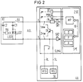
- the two block diagrams 1 and 2 differ in the type of control of the periodic line short circuit.
- Both digital and analog communication terminals can be connected to the program-controlled digital communication switching system KA according to FIG. 1. This is done via appropriately trained line connection devices. For example, 16 such analog communication terminals can be connected via connection lines ASL to an existing line connection device SLMA for the connection of analog communication terminals.
- the central storage device SPE consists of a customer data memory KD, a program memory P and a working memory A.
- the system operating program is stored in the program memory P.
- the customer data such as. B.
- the working memory A serves, among other things, to record temporary data for program sequence control.
- the internal bus IB formed from address, data and control lines can, in a manner not shown further, also be routed to a local bus via corresponding interface devices.
- the control connections to input / output devices, which are not shown, and which are provided for the dynamic relief of the central microprocessor device could be made with a corresponding system size.
- the switching and security control of the communication switching system KA is carried out.
- the call signals are created when there is a connection request for the communication terminal KE. This takes place, for example, through the contact rf of a call relay RF controlled by the microprocessor device MP. With the contact rf, the call signals supplied by the central call generator RTG via the common call line RL are applied to the connecting line in a certain calling rhythm. Due to different periods in which the call signals are switched on to the respective connection line, different call rhythms, e.g. B. for internal call, external call, etc., are effected.
- the central ring tone generator RTG is a subcomponent of a central signaling device SE.
- the AC-shaped call signals applied to the line ASL influence the acoustic call display RA in the communication terminal KE via the capacitor C2.
- this call display can be implemented by a bell device. It is also conceivable to emit an acoustic signal in the form of a tone call by means of a piezoelectric converter.
- only the components of a communication terminal KE required to explain the invention are shown.
- a light indicator is arranged via a capacitor C1.
- this light display is realized by two light-emitting diodes LED1 and LED2 connected in anti-parallel.
- the lighting elements LED1 and LED2 become periodic Short-circuiting of the a, b wires of the connection line ASL activated.
- This periodic short-circuiting can be initialized either by a corresponding operator request or automatically.
- This automatic activation can take place, for example, by means of a voice information system, which is assigned to the communication switching system KA and is not shown. In such a case, the activation of the lighting elements can indicate to the subscriber concerned that a message has been stored in the associated box of the voice information system (Voice Mail System).
- Another possibility is to initiate the activation of the lighting element in the communication terminal by means of an operator order.
- an operator possibly with a restriction to the associated switching center, must then enter a number and / or control character code characteristic of the activation of this feature in addition to the telephone number of the subscriber to be addressed.
- This information then causes the central control unit ZSE to actuate the relay MW periodically by means of corresponding control pulses, so that the connecting line ASL is thereby short-circuited in the predetermined rhythm by the contact mw.
- the capacitor C1 is discharged via the one light-emitting diode LED1 and is charged in the intervening period up to the subsequent short-circuit of the line.
- the optical display provided in the communication terminal could also signal that an attempt to establish a further connection to this communication terminal was attempted during a previous current connection. By pressing a Corresponding input means on this analog communication terminal could then automatically establish a connection to the communication terminal from which this connection request originated with the aid of the communication switching system.
- the intensity of the lighting of the light-emitting diodes LED1, LED2 depends on the feed current of the subscriber circuit of the communication switching system.
- SR1 and SR2 indicate the feed relays present in the subscriber line for the individual lines. So that the indication circuit In provided for each connecting line does not respond, the duration of the short circuit of the connecting line caused by the contact mw must be below the loop detection time.
- the switching means signaling the state of the subscriber line loop in the indication circuit is usually queried by the central control unit ZSE and the corresponding follow-up functions are then initiated on the basis of this query.
- the light-emitting diodes LED1, LED2 are likewise activated by the individual half-waves of the alternating current-shaped call signal in parallel with the activation of the acoustic call signal generator RA. Activating this light display without emitting an acoustic signal, however, enables the above-mentioned information content, which relates, inter alia, to the "message waiting" information.
- the relay MW is not clocked by the microprocessor device MP of the central control unit ZSE, but there is clock information about a central signal line SL in each line connection device SLMA before.
- This clock information is supplied by the central clock generator MG, which is associated with the signaling device SE.
- This clock information is applied to the control input of an electronic switch provided for each connecting line ASL - in the exemplary embodiment in the form of a transistor TR.
- the relay MW is continuously activated by the central control unit ZSE.
- the line wires a, b of the connecting line ASL are bridged by the actuated contacts 1mw, 2mw.
- the effective short circuit occurs in the rhythm of the clock pulses supplied by the generator MG, since the electronic switch in the form of the transistor TR is effectively switched through with each pulse. Since, in this exemplary embodiment, the opening and closing of the switch that short-circuits the line is brought about by the centrally generated clock pulses, this results in a dynamic relief of the central control unit ZSE.
- the time conditions specified for exemplary embodiment 1 apply, that is to say the time duration of the effective short circuit must lie below the response time of the line indication In and the intervening period in each case should be selected to be longer than the time duration of the effective short circuit.
- FIG 2 corresponds to those of FIG 1 and are labeled in the same way.
Landscapes
- Engineering & Computer Science (AREA)
- Signal Processing (AREA)
- Sub-Exchange Stations And Push- Button Telephones (AREA)
Applications Claiming Priority (2)
| Application Number | Priority Date | Filing Date | Title |
|---|---|---|---|
| DE4109310 | 1991-03-21 | ||
| DE4109310 | 1991-03-21 |
Publications (3)
| Publication Number | Publication Date |
|---|---|
| EP0504658A2 true EP0504658A2 (fr) | 1992-09-23 |
| EP0504658A3 EP0504658A3 (en) | 1992-11-04 |
| EP0504658B1 EP0504658B1 (fr) | 1995-12-27 |
Family
ID=6427897
Family Applications (1)
| Application Number | Title | Priority Date | Filing Date |
|---|---|---|---|
| EP92103694A Expired - Lifetime EP0504658B1 (fr) | 1991-03-21 | 1992-03-04 | Procédé pour l'activation d'un affichage optique dans un terminal de communication analogique relié à un système de communication |
Country Status (2)
| Country | Link |
|---|---|
| EP (1) | EP0504658B1 (fr) |
| DE (1) | DE59204791D1 (fr) |
Family Cites Families (3)
| Publication number | Priority date | Publication date | Assignee | Title |
|---|---|---|---|---|
| US4266101A (en) * | 1979-07-18 | 1981-05-05 | Siemens Corporation | Control circuit for a telephone system for the control of visual and audible signals |
| US4438506A (en) * | 1981-08-04 | 1984-03-20 | H & K Computer Corporation | Message waiting light control system |
| JPS61179647A (ja) * | 1984-12-29 | 1986-08-12 | Fujitsu Ltd | サ−ビス表示用ランプの点灯方法 |
-
1992
- 1992-03-04 EP EP92103694A patent/EP0504658B1/fr not_active Expired - Lifetime
- 1992-03-04 DE DE59204791T patent/DE59204791D1/de not_active Expired - Fee Related
Also Published As
| Publication number | Publication date |
|---|---|
| EP0504658A3 (en) | 1992-11-04 |
| DE59204791D1 (de) | 1996-02-08 |
| EP0504658B1 (fr) | 1995-12-27 |
Similar Documents
| Publication | Publication Date | Title |
|---|---|---|
| EP0693848A2 (fr) | Système de communication | |
| DE2036815C3 (de) | Schaltungsanordnung für eine Nebenstellenanlage mit einer beschränkten Anzahl von Nebenstellen | |
| DE2551916A1 (de) | Verfahren und anordnung zur verminderung der speisestromverlustleistung bei teilnehmeranschluessen einer nachrichtenvermittlungsanlage | |
| EP0583716A2 (fr) | Procédé de transmission bidirectionelle de signaux | |
| DE2122743B2 (de) | Nebenstellenanlage | |
| DE1237639B (de) | Schaltungsanordnung zur Steuerung der Verbindungsherstellung ueber ein im Zeitvielfach-betrieb gesteuertes, endmarkiertes Koppelfeld fuer Fernmelde-, insbesondere Fernsprech-vermittlungsanlagen | |
| DE2513695C2 (de) | Schaltungsanordnung für eine Tastenfernsprechanlage | |
| EP0504658B1 (fr) | Procédé pour l'activation d'un affichage optique dans un terminal de communication analogique relié à un système de communication | |
| DE2522957A1 (de) | Schaltungsanordnung fuer ueber ihre anschlussleitungen gespeiste teilnehmerstationen mit impulstastwahl in fernmelde-, insbesondere fernsprechanlagen | |
| DE2743679C2 (de) | Elektronisch gesteuertes Fernsprechsystem mit einem Kundendatenspeicher, einer zentralen Steuereinrichtung und Datenübertragungsleitungen | |
| DE2743637C2 (de) | Elektronisch gesteuertes Fernsprechsystem mit einem Kundendatenspeicher für die Speicherung mehrerer verschiedener Teilnehmerstellen und periferen Geräten individueller Informationen | |
| EP0504716A2 (fr) | Procédé pour l'activation d'un affichage optique dans un appareil de communication relié à un control de commutation | |
| DE3783909T2 (de) | Anordnung zur berichtsmeldung in einem fernsprechsystem. | |
| DE2951522A1 (de) | Schaltungsanordnung fuer einen leitungsuebertrager | |
| DE19647262B4 (de) | Anruf-Signalisierungsvorrichtung zum Betreiben an einem ISDN-Anschluß | |
| DE3036240C2 (de) | Verfahren zur Übertragung von Binärzeichen zwischen einer zentralen Einrichtung und einer Anzahl von Teilnehmerstellen bei Fernsprechvermittlungsanlagen | |
| EP0419973B1 (fr) | Procédé pour activer un affichage optique dans un terminal de communication d'un système de commutation | |
| DE2743623C3 (de) | Elektronisch gesteuertes Fernsprechsystem mit einer elektronische Koppelpunkte aufweisenden Sprechwegedurchschalte- und Tonanschaltekoppelmatrix, sowie mit diesen zugeordneten Haltesätzen | |
| EP0048925B1 (fr) | Circuit pour petits centraux téléphoniques privés à transmission bidirectionnelle de signaux numériques binaires entre un dispositif central et des appareils téléphoniques connectés à ce dispositif | |
| EP0352700B1 (fr) | Méthode pour réaliser une procédure de commande de service spécifique dans un système de communication commandé par calculateur en particulier un système de communication à touches avec la possibilité de branchement sur une connexion existante | |
| DE3926149C2 (de) | Schaltungskarte für eine Telefonzentrale | |
| EP0032741A1 (fr) | Circuit pour la transmission de signaux de et vers un abonné d'un standard téléphonique privé | |
| EP0352735B1 (fr) | Méthode pour réaliser une procédure de commande de service spécifique dans un système de communication commandé par calculateur en particulier un système de communication à touches avec la possibilité de branchement sur une connexion existante | |
| DE3434853C2 (fr) | ||
| DE3804216C2 (fr) |
Legal Events
| Date | Code | Title | Description |
|---|---|---|---|
| PUAI | Public reference made under article 153(3) epc to a published international application that has entered the european phase |
Free format text: ORIGINAL CODE: 0009012 |
|
| PUAL | Search report despatched |
Free format text: ORIGINAL CODE: 0009013 |
|
| AK | Designated contracting states |
Kind code of ref document: A2 Designated state(s): BE DE FR IT |
|
| AK | Designated contracting states |
Kind code of ref document: A3 Designated state(s): BE DE FR IT |
|
| 17P | Request for examination filed |
Effective date: 19921208 |
|
| 17Q | First examination report despatched |
Effective date: 19950508 |
|
| GRAA | (expected) grant |
Free format text: ORIGINAL CODE: 0009210 |
|
| AK | Designated contracting states |
Kind code of ref document: B1 Designated state(s): BE DE FR IT |
|
| REF | Corresponds to: |
Ref document number: 59204791 Country of ref document: DE Date of ref document: 19960208 |
|
| ITF | It: translation for a ep patent filed | ||
| ET | Fr: translation filed | ||
| PLBE | No opposition filed within time limit |
Free format text: ORIGINAL CODE: 0009261 |
|
| STAA | Information on the status of an ep patent application or granted ep patent |
Free format text: STATUS: NO OPPOSITION FILED WITHIN TIME LIMIT |
|
| 26N | No opposition filed | ||
| PGFP | Annual fee paid to national office [announced via postgrant information from national office to epo] |
Ref country code: BE Payment date: 20050311 Year of fee payment: 14 |
|
| PGFP | Annual fee paid to national office [announced via postgrant information from national office to epo] |
Ref country code: FR Payment date: 20050331 Year of fee payment: 14 |
|
| PGFP | Annual fee paid to national office [announced via postgrant information from national office to epo] |
Ref country code: DE Payment date: 20050519 Year of fee payment: 14 |
|
| PG25 | Lapsed in a contracting state [announced via postgrant information from national office to epo] |
Ref country code: BE Free format text: LAPSE BECAUSE OF NON-PAYMENT OF DUE FEES Effective date: 20060331 |
|
| PGFP | Annual fee paid to national office [announced via postgrant information from national office to epo] |
Ref country code: IT Payment date: 20060331 Year of fee payment: 15 |
|
| PG25 | Lapsed in a contracting state [announced via postgrant information from national office to epo] |
Ref country code: DE Free format text: LAPSE BECAUSE OF NON-PAYMENT OF DUE FEES Effective date: 20061003 |
|
| REG | Reference to a national code |
Ref country code: FR Ref legal event code: ST Effective date: 20061130 |
|
| BERE | Be: lapsed |
Owner name: *SIEMENS A.G. Effective date: 20060331 |
|
| PG25 | Lapsed in a contracting state [announced via postgrant information from national office to epo] |
Ref country code: FR Free format text: LAPSE BECAUSE OF NON-PAYMENT OF DUE FEES Effective date: 20060331 |
|
| PG25 | Lapsed in a contracting state [announced via postgrant information from national office to epo] |
Ref country code: IT Free format text: LAPSE BECAUSE OF NON-PAYMENT OF DUE FEES Effective date: 20070304 |