EP0504643B1 - Einrichtung und Verfahren zum Kühlen und/oder Heizen einer Kabine - Google Patents
Einrichtung und Verfahren zum Kühlen und/oder Heizen einer Kabine Download PDFInfo
- Publication number
- EP0504643B1 EP0504643B1 EP92103510A EP92103510A EP0504643B1 EP 0504643 B1 EP0504643 B1 EP 0504643B1 EP 92103510 A EP92103510 A EP 92103510A EP 92103510 A EP92103510 A EP 92103510A EP 0504643 B1 EP0504643 B1 EP 0504643B1
- Authority
- EP
- European Patent Office
- Prior art keywords
- air
- air flow
- duct
- cooling
- heat
- Prior art date
- Legal status (The legal status is an assumption and is not a legal conclusion. Google has not performed a legal analysis and makes no representation as to the accuracy of the status listed.)
- Expired - Lifetime
Links
Images


Classifications
-
- B—PERFORMING OPERATIONS; TRANSPORTING
- B60—VEHICLES IN GENERAL
- B60H—ARRANGEMENTS OF HEATING, COOLING, VENTILATING OR OTHER AIR-TREATING DEVICES SPECIALLY ADAPTED FOR PASSENGER OR GOODS SPACES OF VEHICLES
- B60H1/00—Heating, cooling or ventilating devices
- B60H1/32—Cooling devices
- B60H1/3202—Cooling devices using evaporation, i.e. not including a compressor, e.g. involving fuel or water evaporation
-
- B—PERFORMING OPERATIONS; TRANSPORTING
- B60—VEHICLES IN GENERAL
- B60H—ARRANGEMENTS OF HEATING, COOLING, VENTILATING OR OTHER AIR-TREATING DEVICES SPECIALLY ADAPTED FOR PASSENGER OR GOODS SPACES OF VEHICLES
- B60H1/00—Heating, cooling or ventilating devices
- B60H1/00007—Combined heating, ventilating, or cooling devices
-
- B—PERFORMING OPERATIONS; TRANSPORTING
- B60—VEHICLES IN GENERAL
- B60H—ARRANGEMENTS OF HEATING, COOLING, VENTILATING OR OTHER AIR-TREATING DEVICES SPECIALLY ADAPTED FOR PASSENGER OR GOODS SPACES OF VEHICLES
- B60H1/00—Heating, cooling or ventilating devices
- B60H1/00357—Air-conditioning arrangements specially adapted for particular vehicles
- B60H1/00385—Air-conditioning arrangements specially adapted for particular vehicles for vehicles having an electrical drive, e.g. hybrid or fuel cell
-
- B—PERFORMING OPERATIONS; TRANSPORTING
- B60—VEHICLES IN GENERAL
- B60H—ARRANGEMENTS OF HEATING, COOLING, VENTILATING OR OTHER AIR-TREATING DEVICES SPECIALLY ADAPTED FOR PASSENGER OR GOODS SPACES OF VEHICLES
- B60H1/00—Heating, cooling or ventilating devices
- B60H1/32—Cooling devices
- B60H1/3201—Cooling devices using absorption or adsorption
- B60H1/32014—Cooling devices using absorption or adsorption using adsorption, e.g. using Zeolite and water
Definitions
- the invention relates to a device for temporarily heating or cooling a passenger compartment in a motor vehicle and a method for cooling or heating with such a device.
- cooling channels for a liquid coolant are known, through which all components with heat generation flow, to dissipate the thermal energy from them. Since the temperature profile is subject to very strong fluctuations and, at least for a short time, larger amounts of heat are also to be dissipated, a heat exchanger arranged in the coolant flow must be designed for this most unfavorable maximum operating point with regard to its heat transfer capacity.
- cooling of the passenger compartment at high outside temperatures and possibly high relative air humidity is also desirable, with the energy expenditure for cooling being as low as possible and environmentally friendly substances being used as coolants.
- US-A 2 344 384 describes an air conditioning system for rooms in buildings.
- air is extracted from the room through two channels in the adsorption mode, an air flow being discharged via the adsorber and then into the environment.
- the other air stream is passed through the regenerator, then divided and this partial air stream is passed through the adsorber and fed back into the room.
- cold, dry air is supplied to the room, the amount of air that is supplied being significantly less than the amount of air that is removed.
- a humidifier is not provided in this mode. The system works in continuous operation.
- Cold air is also supplied to the room during desorption, with one immediately before entering the room Humidification device is provided.
- Two of the three existing fans are reversible with respect to their air flow direction, so that the air flow through the adsorber and regenerator is reversible.
- the heating device shown serves only to heat the adsorber air which is emitted into the environment on the outlet side of the adsorber. The heat of the air flow discharged from the room is not recovered.
- the operation is isothermal both in the adsorption and in the desorption.
- EP-A 0 167 096 describes an air conditioning system with storage heating for rooms in a building, which comprises three adsorber columns. The process thus carried out is a closed cycle. The moisture is condensed out; the resulting temperature is brought to a higher level by a heat pump and returned to the reactor. Electrical energy is required for desorption and heat is recovered by condensation. In the case of cooling, desorption is achieved with the help of solar energy.
- the invention has for its object to provide a device for temporarily heating or cooling a passenger compartment in a vehicle without or with the internal combustion engine not in operation, with which heating or cooling is possible with low energy consumption and using environmentally friendly substances.
- a device with the features of claim 1 Such a device with a sorption reactor requires little auxiliary energy during the heating or cooling of a passenger compartment.
- Zeolite is an environmentally friendly sorbent and enables simple, maintenance-friendly construction of a heating or cooling device.
- the passenger compartment air is drawn off according to the invention via the exhaust air duct, preferably via an air / air heat exchanger and the inflow duct of the reaction chamber fed.
- the dehumidified air emerging from the outflow channel of the reaction chamber is cooled with ambient air in a first air / air heat exchanger and exhaust air from the passenger compartment in a second air / air heat exchanger, adiabatically cooled in an evaporator by evaporation of water to the cooling limit and then can be introduced directly into the passenger compartment via the supply air duct.
- a moist air stream is supplied via the inflow channel to the reaction chamber, which is dehumidified by adsorption in the sorption reactor and thereby absorbs heat
- the dry hot air stream emerging from the outflow channel receiving its heat energy in an air / air heat exchanger emits a cooling air flow which is supplied to the passenger compartment as a heating air flow.
- the cooling air flow can be composed of freely selectable proportions of fresh air and recirculated air.
- the exhaust air from the passenger compartment flows through an evaporator, from which the moist air flows preheated to the sorption reactor through a further heat exchanger.
- an exhaust air duct which can be acted upon by an air flow by means of a further air flow control element is provided for removing heat.
- a cooler which is located in a cooling circuit of the drive components and is acted upon by its coolant, is provided as the heat source, the cooling fan and the cooler being arranged one behind the other in the air duct.
- a first air flow control element is also installed, which controls the proportion of circulating air and exhaust air.
- a second air flow control element controls the proportion of heating air introduced into the passenger compartment and cooling air discharged to the surroundings.
- the sorption reactor is arranged after the second air flow control element.
- Additional auxiliary units with heat generation can be connected to the cooling circuit, a coolant pump being driven by an electric motor for circulating the coolant.
- a coolant pump being driven by an electric motor for circulating the coolant.
- the coolant is fed to it at a relatively constant temperature level.
- a heat accumulator is provided before the coolant enters the cooler, which compensates for the extreme fluctuations in the heat development in the individual components.
- a latent heat accumulator is particularly suitable at this point, by means of which it is possible to immediately provide thermal energy for heating the passenger compartment again after a brief interruption in the journey.
- the device for heating or cooling a passenger compartment 10 of a motor vehicle which is shown schematically in FIGS. 1 to 4, has a sorption reactor 20 with a sorbent, such as zeolite or the like, as an energy store (heat source) and air channels through which, according to the operating state, air flow control elements Air flows are guided.
- a sorption reactor 20 with a sorbent such as zeolite or the like, as an energy store (heat source) and air channels through which, according to the operating state, air flow control elements Air flows are guided.
- An air flow is supplied to the reaction chamber 21 of the sorption reactor 20 via an inflow duct 22, which in cooling operation via an exhaust air duct 11 and in heating operation via an evaporator 13, the supply air duct 12, the air flow control element 54, the air duct 7 and the lust flow control element 53 is suctioned off.
- the exhaust air duct 11 is connected to the inflow duct 22 via an air flow control element 51, which in position 1 establishes a flow connection between the inflow duct 22 and the exhaust air duct and closes the exhaust air duct 11 in a position 2 and connects the inflow duct 22 to a fresh air duct 8.
- the outflow duct 23 of the reaction chamber 21 carrying a dry warm air flow is connected in cooling operation via an air flow control element 50 to an inlet air duct 12 of the passenger compartment 10.
- an air flow control element 50 to an inlet air duct 12 of the passenger compartment 10.
- the hot air flow from the outflow duct 23 enters the supply air duct 12, while in position 2 of the air flow control element 50 the supply air duct 12 is closed and the outflow duct 23 opens into an exhaust air duct 9.
- An evaporator 13 is arranged in the supply air duct 12, preferably directly adjacent to the passenger compartment 10. From a water reservoir 15, suitable surfaces 17 for evaporation are supplied to water by means of a pump 16 via a valve 14.
- the outflow channel 23 and the inflow channel 22 are in heat-transferring connection.
- a heat exchanger 24, preferably a cross-flow heat exchanger, is arranged.
- a further evaporator 25 with suitable surfaces 26 is advantageously arranged in the inflow channel 22.
- a heat-dissipating heat exchanger 27 is arranged between the sorption reactor 20 and the cross-flow heat exchanger 24 and can form a structural unit with the heat exchanger 24.
- the heat exchanger 27 is from a cooling air flow 28 flows through, which is generated by a cooling fan 29.
- the cooling air flow emerging from the heat exchanger 27 is discharged into the atmosphere via a connecting duct 30 and an exhaust air duct 31.
- air is drawn off via the exhaust air duct 11, which flows through the heat exchanger 24 as an exhaust air flow and is heated.
- the exhaust air flow enters the sorption reactor 20 via the inflow channel 22.
- the sorbent in the exemplary embodiment shown zeolite, adsorbs the moisture, generating heat of adsorption which leads to the heating of the air flowing through.
- the air emerging from the outflow duct 23 is thus a dry warm air flow which is cooled in the heat exchanger 27 by the cooling air flow 28 and in the heat exchanger 24 emits the residual heat for heating the exhaust air drawn off from the passenger compartment.
- the cooled, dried air flows via the control element 50 into the supply air duct 12 and the evaporator 13, where it is cooled adiabatically with evaporation of water up to the cooling limit.
- the cooled air preferably exits the evaporator directly into the passenger compartment.
- the passenger compartment can be cooled by drying in the sorption reactor, pre-cooling in the heat exchangers and adiabatic rewetting of the air.
- the air flow from the passenger compartment 10 to the sorption reactor 20 and back to the passenger compartment is maintained by means of a circulating air blower 19 which is arranged in the inflow duct 22.
- a heating device 18 is arranged in the inflow channel 22 before entering the reaction chamber 21, the operation of which will be described below.
- a bridge duct 7 connects the inflow duct 22 to the supply air duct 12 via air flow control elements 53 and 54.
- the connecting duct 30 is designed to open into the passenger compartment 10, the exhaust air duct 31 being connected via an air flow control element 52.
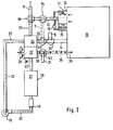
- the air flow control elements 50, 52, 53 and 54 are switched to position 2 as shown in FIG. 2, so that their flaps open the bridge channel 7 and the connecting channel 30.
- warm exhaust air is drawn in from the passenger compartment 10 via the supply air duct 12, which preferably absorbs water in the evaporator 13 until saturation.
- the exhaust air enters the inflow duct 22 via the bridge duct 7 and the control element 53 and, as described in FIG. 1, flows through the reaction chamber 21 of the sorption reactor 20.
- the hot air emerging via the outflow duct 23 gives it Heat in the heat exchanger 27 to the cooling air flow 28, which is generated by the cooling fan 29.
- the cooling air flow is composed of fresh air and recirculated air, the recirculated air being sucked out of the passenger compartment by means of blowers 29 via the air flow control element 60 and the air duct 32.
- the cooling air flow 28 enters the passenger compartment 10 as heating air via the connecting duct 30.
- the cooled air exits into the atmosphere via the exhaust air duct 9.
- the device can also be used for heating as shown in FIG. 3.
- Fresh air is supplied to the inflow duct 22 via the fresh air duct 8 and the air flow control element 51 in position 2. This fresh air is warmed in the cross-flow heat exchanger 24 and humidified via the evaporator 25 until saturation.
- the heated, humidified fresh air flows into the reaction chamber 21 of the sorption reactor 20 and exits as a dry warm air flow through the outflow duct 23, which is connected to the exhaust air duct 9 via the air flow control element 50 in position 2.
- the heat of adsorption discharged from the sorption reactor 20 is given off to the cooling air flow 28, which enters the passenger compartment 10 as heating air via the connecting duct 30.
- the cooling fan 29 draws in cabin air via a recirculation air duct 32, with fresh air being simultaneously drawn in from a fresh air duct 33 via a control element 60.
- a corresponding proportion of fresh air can be supplied to the intake air, this mixed air flow flowing through the heat exchanger 27 as cooling air flow and entering the passenger compartment 10 as heating air.
- the sorption reactor If the sorption reactor has absorbed a certain amount of water, it must be desorbed for regeneration.
- fresh air is supplied to the inflow channel 22 via the fresh air channel 8 and is heated in the heating device 18 before entering the reaction chamber 21.
- An electrical heating register can be used as the heating device 18 used, which is in operation, for example, when charging the batteries of an electric vehicle; in a vehicle with an internal combustion engine, the necessary thermal energy can be extracted from the exhaust gas via a heat exchanger.
- the heated fresh air absorbs water from the sorbent and discharges it via the outflow duct 23 and the heat exchanger 24 and the exhaust air duct 9.
- the moist, warm air from the sorption reactor gives off heat to the fresh air, as a result of which part of the waste heat is recovered.
- the end of the desorption process can be determined on the basis of an increase in the temperature in the outflow channel 23.
- the temperature rise at the end of the desorption process can advantageously be used to heat the passenger compartment 10, for which purpose the cooling fan 29 must be switched on and the cooling air flow can be supplied to the passenger compartment as heating air via the connecting duct 30.
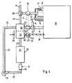
- the exemplary embodiment of the device according to the invention according to FIG. 5 serves exclusively to heat a passenger compartment 10, for example an electric vehicle.
- a passenger compartment 10 for example an electric vehicle.
- exhaust air is drawn in via the exhaust air duct 11 and fresh air is drawn in via the duct 36 and blown into the passenger compartment 10 via the supply air duct 12.
- An exhaust air portion corresponding to the fresh air portion is emitted to the environment via the exhaust air connector 37.
- a fan 6 arranged in the supply air duct 12 ensures adequate air circulation.
- a heat exchanger 27 preferably a cross-flow heat exchanger, is arranged in the supply air duct 12, through which the dry warm air is led and which releases the absorbed heat of absorption to the circulating air flow.
- the inflow duct 22 to the reaction chamber 21 of the sorption reactor 20 is connected to the outflow duct 23 via a circulating air duct 38.
- the air circulation in the closed circuit thus formed is maintained by the circulating air blower 19.
- the dry circulating air of the sorption reactor, cooled by the heat given off in the heat exchanger 27, is humidified to the saturation limit in the evaporator 25 before re-entering the reaction chamber 21.
- the evaporator has a water circuit operated by a pump 25a, which permanently applies water from a water reservoir 25b to suitable surfaces 26 for evaporation.
- a heat exchanger 40 of a cooling circuit 41 is advantageously integrated in the evaporator 25 and removes any waste heat that may be present from any units.
- the heat-absorbing side of the cooling circuit operated by the pump 43 is stylized by a circle 42.
- the outflow duct 23 can optionally be connected to the exhaust air duct 9 or the recirculated air duct 38 via the air flow control element 50, while the fresh air duct 8 or the recirculated air duct 38 can optionally be connected to the inflow duct 22 via the air flow control element 51 integrated in the fan.
- the cooling air blower 19 sucks in fresh air via the fresh air duct 8, which can be blown off via an exhaust air duct 31, via the air flow control element located in position 1 52 branches off between the evaporator 25 and the sorption reactor 20.
- the heat-storing sorption reactor 20 has to be desorbed, this can be done - as described in relation to FIG. 4 - by opening the fresh air duct and the exhaust air duct with the addition of thermal energy. It is preferably provided to arrange a bypass duct 39 which bypasses the fan 19 and which connects to the aforementioned ducts via air flow control elements 55 and 56 between the inflow duct 22 and the circulating air duct 38.
- sufficient heating of the passenger compartment is also possible in the case of an electric vehicle, a hybrid vehicle or another vehicle without an internal combustion engine, as well as in the case of stationary air conditioning.
- the small amounts of heat to be dissipated in a vehicle without an internal combustion engine can advantageously be used to enrich the reaction air supplied to the sorption reactor 20 with water.
- the air flow required for heat absorption in the cooler 40 which is generated by the circulating air blower 19, is sucked in at least approximately completely through the fresh air duct 8 and through the cooler to it second airflow control 52 blown. If there is no heating requirement for the passenger compartment 10, the second air flow control element 52 is in a position which discharges the entire air volume blown by the cooler 40 through the exhaust air duct 31 to the outside.
- the airflow control elements are shown in the blocking position or in the through position. Depending on the desired temperature of the cooling air flow and the heating air, regulation by a large number of intermediate positions of these air flow control elements is possible.
Landscapes
- Engineering & Computer Science (AREA)
- Physics & Mathematics (AREA)
- Thermal Sciences (AREA)
- Mechanical Engineering (AREA)
- Life Sciences & Earth Sciences (AREA)
- Sustainable Development (AREA)
- Sustainable Energy (AREA)
- Air-Conditioning For Vehicles (AREA)
- Sorption Type Refrigeration Machines (AREA)
Description
- Die Erfindung betrifft eine Einrichtung zum zeitweisen Heizen oder Kühlen eines Fahrgastraums in einem Kraftfahrzeug und ein Verfahren zum Kühlen oder Heizen mit einer derartigen Einrichtung.
- Bei bekannten Kraftfahrzeugen mit einem Verbrennungsmotor steht eine ausreichende abzuführende Wärmemenge zur Verfügung, die auch an kalten Wintertagen eine ausreichende Heizung des Fahrgastraums ermöglicht. Bei Kraftfahrzeugen ohne Verbrennungsmotor, wie z.B. bei Elektrofahrzeugen, Hybridfahrzeugen oder dgl., fällt nur in geringem Umfang Abwärme an, die zum Heizen des Fahrgastraums nicht ausreichend ist. Gleiches gilt für die Klimatisierung eines Fahrgastraums, wenn der Verbrennungsmotor nicht in Betrieb ist.
- Zur Kühlung der Antriebskomponenten eines Elektrofahrzeuges sind Kühlkanäle für ein flüssiges Kühlmittel bekannt, über die alle Komponenten mit Wärmeentwicklung durchströmt sind, um aus diesen die Wärmeenergie abzuführen. Da das Temperaturprofil sehr starken Schwankungen unterliegt und, zumindest kurzzeitig, auch größere Wärmemengen abzuführen sind, muß ein in dem Kühlmittelstrom angeordneter Wärmetauscher bezüglich seiner Wärmeübertragungsleistung auf diesen ungünstigsten maximalen Betriebspunkt ausgelegt werden.
- Neben der Wärmeabführung aus den Antriebskomponenten ist auch eine Kühlung des Fahrgastraums bei hohen Außentemperaturen und eventuell hoher relativer Luftfeuchte wünschenswert, wobei der Energieaufwand zur Kühlung möglichst gering sein soll und als Kühlmittel umweltverträgliche Stoffe Verwendung finden sollen.
- Die US-A 2 344 384 beschreibt eine Klimaanlage für Räume in Gebäuden. Bei dieser Einrichtung wird im Adsorptionsbetrieb dem Raum durch zwei Kanäle Luft entnommen, wobei ein Luftstrom über den Adsorber und dann in die Umgebung abgeleitet wird. Der andere Luftstrom wird über den Regenerator geführt, anschließend geteilt und dieser Teilluftstrom durch den Adsorber geleitet und wieder dem Raum zugeführt. In diesem Fall wird dem Raum kalte, trockene Luft zugeführt, wobei die Luftmenge, die zugeführt wird, wesentlich geringer ist als die abgeführte Luftmenge. Eine Befeuchtungseinrichtung ist bei dieser Betriebsart nicht vorgesehen. Die Anlage arbeitet im kontinuierlichen Betrieb.
- Auch bei der Desorption wird dem Raum kalte Luft zugeführt, wobei unmittelbar vor dem Eintritt in den Raum eine Befeuchtungseinrichtung vorgesehen ist. Zwei der drei vorhandenen Ventilatoren sind bezüglich ihrer Luftförderrichtung umkehrbar, so daß der Luftstrom durch den Adsorber und Regenerator reversibel ist. Die dargestellte Heizeinrichtung dient allein zur Aufheizung der Adsorberluft, welche ausgangsseitig des Adsorbers in die Umgebung abgegeben wird. Eine Rückgewinnung der Wärme des aus dem Raum abgeführten Luftstroms erfolgt nicht. Bei dem bekannten Gegenstand ist sowohl bei der Adsorption als auch bei der Desorption der Betrieb isotherm.
- In der EP-A 0 167 096 ist eine Klimaanlage mit Speicherheizung für Räume eines Gebäudes beschrieben, die drei Adsorberkolonnen umfaßt. Bei dem damit durchgeführten Verfahren handelt es sich um einen geschlossenen Kreisprozeß. Die Feuchtigkeit wird auskondensiert; die dabei entstehende Temperatur wird durch eine Wärmepumpe auf ein höheres Niveau gebracht und wieder dem Reaktor zugeführt. Zur Desorption wird elektrische Energie benötigt, und es erfolgt eine Wärmerückgewinnung durch Kondensation. Im Kühlfall wird die Desorption mit Hilfe von Sonnenenergie erreicht.
- Bezüglich des Heizvorgangs, d.h. zum Aufheizen der Raumluft in der EP-A 0 167 096 ist anzumerken, daß es sich um ein kontinuierliches System handelt, bei dem ohne Frischluftanteil dem Raum warme Luft direkt aus dem Reaktor zugeführt wird. Hierzu erforderlich ist der Betrieb von drei Kolonnen. Auch das Kühlen der Raumluft erfolgt im Drei-Kolonnen-Betrieb, wobei durch Adsorption trockene Luft erzeugt wird. Dieser Vorgang erfolgt isotherm. Bei der bekannten Anordnung muß eine Richtungsänderung des Luftstromes im Reaktor erfolgen. Aufgrund des Kolonnen-Betriebs mit nacheinander beaufschlagbaren Reaktorkolonnen wird bei der bekannten Anordnung gleichzeitig eine Desorption und in einer anderen Kolonne eine Adsorption durchgeführt.
- Der Erfindung liegt die Aufgabe zugrunde, eine Einrichtung zum zeitweisen Heizen oder Kühlen eines Fahrgastraums in einem Fahrzeug ohne oder mit nicht in Betrieb befindlichem Verbrennungsmotor anzugeben, mit dem bei geringem Energieverbrauch und unter Verwendung umweltverträglicher Stoffe ein Heizen oder Kühlen möglich ist.
- Die Aufgabe wird erfindungsgemäß durch eine Einrichtung mit den Merkmalen des Anspruchs 1 gelöst. Eine derartige Einrichtung mit einem Sorptionsreaktor benötigt während des Heizens oder Kühlens eines Fahrgastraums nur wenig Hilfsenergie. Zeolith ist ein umweltverträglicher Sorbens und ermöglicht einen einfachen, wartungsfreundlichen Aufbau einer Heiz- oder Kühleinrichtung.
- Zum Kühlen des Fahrgastraumes wird erfindungsgemäß die Fahrgastraumluft über den Abluftkanal abgezogen, vorzugsweise über einen Luft/Luft-Wärmetauscher und den Zuströmkanal der Reaktionskammer zugeführt. Die aus dem Abströmkanal der Reaktionskammer austretende, entfeuchtete Luft wird in einem ersten Luft/Luft-Wärmetauscher mit Umgebungsluft und in einem zweiten Luft/Luft-Wärmetauscher mit Fahrgastraumabluft gekühlt, in einem Verdunster durch Verdunsten von Wasser bis zur Kühlgrenze adiabatisch weiter abgekühlt und kann dann über den Zuluftkanal unmittelbar in den Fahrgastraum eingeleitet werden.
- Soll die erfindungsgemäße Einrichtung zum Heizen benutzt werden, wird über den Zuströmkanal der Reaktionskammer ein feuchter Luftstrom zugeführt, der durch Adsorption im Sorptionsreaktor entfeuchtet wird und dabei Wärme aufnimmt, wobei der aus dem Abströmkanal austretende trockene Warmluftstrom seine Wärmeenergie in einem Luft/Luft-Wärmetauscher an einen Kühlluftstrom abgibt, der als Heizluftstrom dem Fahrgastraum zugeführt ist. Der Kühlluftstrom kann sich in frei wählbaren Anteilen aus Frischluft und Umluft zusammensetzen. Die Abluft aus dem Fahrgastraum strömt durch einen Verdunster, aus dem die feuchte Luft durch einen weiteren Wärmetauscher vorgewärmt zum Sorptionsreaktor strömt.
- In Weiterbildung der Erfindung ist zum Abführen von Wärme ein mittels eines weiteren Luftstromsteuerelementes von einem Luftstrom beaufschlagbarer Fortluftkanal vorgesehen. Als Wärmequelle ist ein in einem Kühlkreislauf der Antriebskomponenten befindlicher und von dessen Kühlmittel beaufschlagter Kühler vorgesehen, wobei das Kühlgebläse und der Kühler hintereinander in dem Luftführungskanal angeordnet sind. Strömungsmäßig vor dem Kühler ist ferner ein erstes Luftstromsteuerelement eingebaut, das den Anteil von Umluft und Fortluft steuert.
- Strömungsmäßig nach dem Kühler steuert ein zweites Luftstromsteuerelement den Anteil von in den Fahrgastraum eingeleiteter Heizluft und an die Umgebung abgeführter Kühlluft. Der Sorptionsreaktor ist nach dem zweiten Luftstromsteuerelement angeordnet.
- Aufgrund der Steuerelemente und des Gebläses ist stets ein ausreichender Kühlluftstrom durch den Kühler bereitgestellt, wohingegen die aus dem Kühler abgeführte Wärmeenergie und auch die im Umluftstrom des Luftführungskanals enthaltene Wärmeenergie lediglich im Bedarfsfall und entsprechend der benötigten Wärmemenge gezielt dem Fahrgastraum zugeführt wird. Außerdem wird die zugeführte Luft entfeuchtet.
- An den Kühlkreislauf können weitere Zusatzaggregate mit Wärmeentwicklung angeschlossen sein, wobei für die Umwälzung des Kühlmittels eine Kühlmittelpumpe vorgesehen ist, die von einem Elektromotor angetrieben wird. Um eine optimale Auslegung des Kühlers zu erreichen, ist es zweckmäßig, wenn diesem die Kühlflüssigkeit mit einem relativ konstanten Temperaturniveau zugeleitet wird. Zu diesem Zweck ist vor Eintritt des Kühlmittels in den Kühler ein Wärmespeicher vorgesehen, der die extremen Schwankungen der Wärmeentwicklung in den einzelnen Komponenten kompensiert. Beesonders geeignet ist an dieser Stelle ein Latentwärmespeicher, durch den es möglich ist, nach kurzer Fahrtunterbrechung sofort wieder Wärmeenergie zum Heizen des Fahrgastraumes zur Verfügung zu stellen.
- Weitere Merkmale der Erfindung ergeben sich aus den weiteren Ansprüchen, der Beschreibung und der Zeichnung, in der nachfolgend im einzelnen beschriebene Ausführungsbeispiele der Erfindung dargestellt sind. Es zeigen:
- Fig. 1
- in schematischer Darstellung eine erfindungsgemäße Einrichtung im Betriebszustand zum Kühlen eines Fahrgastraumes,
- Fig. 2
- in schematischer Darstellung eine Einrichtung gemäß Fig. 1 im Betriebszustand zum Heizen eines Fahrgastraumes,
- Fig. 3
- in schematischer Darstellung ein weiteres Ausführungsbeispiel einer erfindungsgemäßen Einrichtung im Betriebszustand zum Heizen eines Fahrgastraumes,
- Fig. 4
- in schematischer Darstellung die Einrichtung nach Fig. 1 im Betriebszustand Desorbieren,
- Fig. 5
- ein weiteres Ausführungsbeispiel einer erfindungsgemäßen Einrichtung zum Heizen eines Fahrgastraumes.
- Die in den Fig. 1 bis 4 schematisch dargestellte Einrichtung zum Heizen oder Kühlen eines Fahrgastraumes 10 eines Kraftfahrzeugs weist als Energiespeicher (Wärmequelle) einen Sorptionsreaktor 20 mit einem Sorbens, wie Zeolith oder dgl., auf sowie Luftkanälen, durch die entsprechend dem Betriebszustand mittels Luftstromsteuerelementen Luftströme geführt sind.
- Der Reaktionskammer 21 des Sorptionsreaktors 20 ist über einen Zuströmkanal 22 ein Luftstrom zugeführt, der im Kühlbetrieb über einen Abluftkanal 11 und im Heizbetrieb über einen Verdunster 13, den Zuluftkanal 12, das Luftstromsteuerelement 54, den Luftkanal 7 und das Luststromsteuerelement 53 abgesaugt wird. Der Abluftkanal 11 ist mit dem Zuströmkanal 22 über ein Luftstromsteuerelement 51 verbunden, welches in der Stellung 1 eine Strömungsverbindung zwischen dem Zuströmkanal 22 und dem Abluftkanal herstellt und in einer Stellung 2 den Abluftkanal 11 verschließt und den Zuströmkanal 22 mit einem Frischluftkanal 8 verbindet.
- Der einen trockenen Warmluftstrom führende Abströmkanal 23 der Reaktionskammer 21 ist im Kühlbetrieb über ein Luftstromsteuerelement 50 mit einem Zuluftkanal 12 des Fahrgastraumes 10 verbunden. In der Stellung 1 tritt der Warmluftstrom aus dem Abströmkanal 23 in den Zuluftkanal 12, während in der Stellung 2 des Luftstromsteuerelementes 50 der Zuluftkanal 12 verschlossen ist und der Abströmkanal 23 in einen Fortluftkanal 9 mündet.
- Im Zuluftkanal 12 ist - bevorzugt unmittelbar benachbart zum Fahrgastraum 10 - ein Verdunster 13 angeordnet. Aus einem Wasserspeicher 15 wird mittels einer Pumpe 16 über ein Ventil 14 Wasser geeigneten Oberflächen 17 zur Verdunstung zugeführt.
- Der Abströmkanal 23 und der Zuströmkanal 22 stehen in wärmeübertragender Verbindung. Hierzu ist ein Wärmetauscher 24, vorzugsweise ein Kreuzstromwärmetauscher, angeordnet. Vorteilhaft ist im Zuströmkanal 22 ein weiterer Verdunster 25 mit geeigneten Oberflächen 26 angeordnet.
- Zwischen dem Sorptionsreaktor 20 und dem Kreuzstromwärmetauscher 24 ist ein wärmeabführender Wärmetauscher 27 angeordnet, der mit dem Wärmetauscher 24 eine Baueinheit bilden kann. Der Wärmetauscher 27 ist von einem Kühlluftstrom 28 durchströmt, welcher von einem Kühlgebläse 29 erzeugt ist. Der aus dem Wärmetauscher 27 austretende Kühlluftstrom ist über einen Verbindungskanal 30 und einen Fortluftkanal 31 in die Atmosphäre abgeführt.
- Zur Kühlung des Fahrgastraumes 10 wird über den Abluftkanal 11 Luft abgezogen, welche als Fortluftstrom den Wärmetauscher 24 durchströmt und erwärmt wird. Der Abluftstrom tritt über den Zuströmkanal 22 in den Sorptionsreaktor 20 ein. Das Sorbens, im gezeigten Ausführungsbeispiel Zeolith, adsorbiert die Feuchte, wobei Adsorptionswärme entsteht, die zur Aufheizung der durchströmten Luft führt. Die aus dem Abströmkanal 23 austretende Luft ist somit ein trockener Warmluftstrom, der im Wärmetauscher 27 durch den Kühlluftstrom 28 abgekühlt wird und im Wärmetauscher 24 die Restwärme zur Aufheizung der aus dem Fahrgastraum abgezogenen Abluft abgibt. Über das Steuerelement 50 strömt die abgekühlte, getrocknete Luft in den Zuluftkanal 12 und den Verdunster 13, wo sie unter Verdunsten von Wasser bis zur Kühlgrenze adiabatisch abgekühlt wird. Die abgekühlte Luft tritt aus dem Verdunster vorzugsweise unmittelbar in den Fahrgastraum ein. Durch Trocknung im Sorptionsreaktor, Vorkühlung in den Wärmetauschern und adiabatische Wiederbefeuchtung der Luft kann so der Fahrgastraum gekühlt werden.
- Die Luftströmung von dem Fahrgastraum 10 zum Sorptionsreaktor 20 und zurück zum Fahrgastraum wird mittels eines Umluftgebläses 19 aufrechterhalten, welches im Zuströmkanal 22 angeordnet ist. Im Zuströmkanal 22 ist vor Eintritt in die Reaktionskammer 21 ferner eine Heizvorrichtung 18 angeordnet, deren Funktionsweise nachfolgend noch beschrieben wird.
- Soll die Einrichtung gemäß Fig. 1 nicht nur zum Kühlen eines Fahrgastraumes 10 verwendet werden, sind gemäß dem gezeigten Ausführungsbeispiel die strichliert gezeichneten Kanäle anzuordnen. Ein Brückenkanal 7 verbindet über Luftstromsteuerelemente 53 und 54 den Zuströmkanal 22 mit dem Zuluftkanal 12. Der Verbindungskanal 30 ist in den Fahrgastraum 10 mündend ausgebildet, wobei der Fortluftkanal 31 über ein Luftstromsteuerelement 52 angeschlossen ist.
- Zum Heizen des Fahrgastraumes 10 werden gemäß Fig. 2 die Luftstromsteuerelemente 50, 52, 53 und 54 in Stellung 2 umgeschaltet, so daß deren Klappen den Brückenkanal 7 bzw. den Verbindungskanal 30 öffnen.
- In diesem Fall wird über den Zuluftkanal 12 aus dem Fahrgastraum 10 warme Abluft angesaugt, die vorzugsweise im Verdunster 13 bis zur Sättigung Wasser aufnimmt. Über den Zuluftkanal 12 und das Steuerelement 54 tritt die Fortluft über den Brückenkanal 7 und das Steuerelement 53 in den Zuströmkanal 22 ein und durchströmt - wie in Fig. 1 beschrieben - die Reaktionskammer 21 des Sorptionsreaktors 20. Die über den Abströmkanal 23 austretende Warmluft gibt ihre Wärme im Wärmetauscher 27 an den Kühlluftstrom 28 ab, der vom Kühlgebläse 29 erzeugt ist. Der Kühlluftstrom setzt sich aus Frischluft und Umluft zusammen, wobei die Umluft über das Luftstromsteuerelement 60 und den Luftkanal 32 aus dem Fahrgastraum mittels Gebläse 29 abgesaugt wird. Der Kühlluftstrom 28 tritt als Heizluft über den Verbindungskanal 30 in den Fahrgastraum 10 ein. Die abgekühlte Luft tritt über den Fortluftkanal 9 in die Atmosphäre aus.
- Alternativ kann die Einrichtung auch zum Heizen gemäß der Darstellung in Fig. 3 benutzt werden. Über den Frischluftkanal 8 und das in Stellung 2 stehende Luftstromsteuerelement 51 wird Frischluft dem Zuströmkanal 22 zugeführt. Diese Frischluft wird im Kreuzstromwärmetauscher 24 angewärmt und über den Verdunster 25 bis zur Sättigung befeuchtet. Die angewärmte, befeuchtete Frischluft strömt in die Reaktionskammer 21 des Sorptionsreaktors 20 ein und tritt als trockener Warmluftstrom durch den Abströmkanal 23 aus, der über das in Stellung 2 stehende Luftstromsteuerelement 50 mit dem Fortluftkanal 9 verbunden ist. Über den Wärmetauscher 27 wird die aus dem Sorptionsreaktor 20 abgeführte Adsorptionswärme an den Kühlluftstrom 28 abgegeben, welcher als Heizluft über den Verbindungskanal 30 in den Fahrgastraum 10 eintritt.
- Das Kühlgebläse 29 saugt über einen Umluftkanal 32 Kabinenluft an, wobei über ein Regelorgan 60 aus einem Frischluftkanal 33 gleichzeitig Frischluft angesaugt wird. Je nach den Betriebsbedingungen kann der angesaugten Luft ein entsprechender Anteil Frischluft zugeführt werden, wobei dieser Mischluftstrom als Kühlluftstrom den Wärmetauscher 27 durchströmt und als Heizluft in den Fahrgastraum 10 eintritt.
- Bei der Ausführung gemäß Fig. 3 kann der in den Fig. 1 und 2 strichliert dargestellte Brückenkanal 7 entfallen.
- Hat der Sorptionsreaktor eine bestimmte Wassermenge aufgenommen, muß zur Regeneration desorbiert werden. Hierzu wird, wie in Fig. 4 dargestellt, über den Frischluftkanal 8 dem Zuströmkanal 22 Frischluft zugeführt, welche vor Eintritt in die Reaktionskammer 21 in der Heizvorrichtung 18 aufgeheizt wird. Als Heizvorrichtung 18 kann ein elektrisches Heizregister verwendet werden, welches zum Beispiel beim Aufladen der Akkumulatoren eines Elektrofahrzeugs in Betrieb ist; bei einem Fahrzeug mit Verbrennungsmotor kann die notwendige Wärmeenergie dem Abgas über einen Wärmetauscher entnommen werden. Die aufgeheizte Frischluft nimmt Wasser aus dem Sorbens auf und führt dieses über den Abströmkanal 23 und den Wärmetauscher 24 sowie den Fortluftkanal 9 ab. Im Wärmetauscher 24 gibt die feuchte, warme Luft aus dem Sorptionsreaktor Wärme an die Frischluft ab, wodurch ein Teil der Abwärme zurückgewonnen wird. Das Ende des Desorptionsvorgangs kann anhand eines Anstiegs der Temperatur im Abströmkanal 23 festgestellt werden. Vorteilhaft kann der Temperaturanstieg am Ende des Desorptionsvorgangs zum Heizen des Fahrgastraumes 10 ausgenutzt werden, wozu das Kühlgebläse 29 einzuschalten ist und der Kühlluftstrom als Heizluft über den Verbindungskanal 30 dem Fahrgastraum zugeführt werden kann.
- Das Ausführungsbeispiel der erfindungsgemäßen Einrichtung gemäß Fig. 5 dient ausschließlich der Heizung eines Fahrgastraums 10, beispielsweise eines Elektrofahrzeugs. Hierbei wird in einem Luftstromsteuerelement 35 über den Abluftkanal 11 Abluft und über den Kanal 36 Frischluft angesaugt und über den Zuluftkanal 12 in den Fahrgastraum 10 geblasen. Ein dem Frischluftanteil entsprechender Fortluftanteil wird über den Fortluftstutzen 37 an die Umgebung abgegeben. Ein im Zuluftkanal 12 angeordnetes Gebläse 6 stellt eine ausreichende Luftumwälzung sicher.
- Wie bereits zu den vorhergehenden Ausführungsbeispielen nach den Fig. 1 bis 4 beschrieben, ist im Zuluftkanal 12 ein Wärmetauscher 27, vorzugsweise ein Kreuzstromwärmetauscher, angeordnet, durch den die trockene Warmluft geführt ist und die aufgenommene Adsorptionswärme an den Umluftstrom abgibt.
- Der Zuströmkanal 22 zur Reaktionskammer 21 des Sorptionsreaktors 20 ist über einen Umluftkanal 38 mit dem Abströmkanal 23 verbunden. Die Luftzirkulation in dem so gebildeten, geschlossenen Kreislauf wird durch das Umluftgebläse 19 aufrechterhalten. Die trockene, durch die Wärmeabgabe im Wärmetauscher 27 abgekühlte Umluft des Sorptionsreaktors wird vor Wiedereintritt in die Reaktionskammer 21 in dem Verdunster 25 bis zur Sättigungsgrenze befeuchtet. Der Verdunster weist einen von einer Pumpe 25a betriebenen Wasserkreislauf auf, der permanent aus einem Wasserreservoir 25b Wasser auf geeignete Oberflächen 26 zur Verdunstung aufbringt. Vorteilhaft ist im Verdunster 25 ein Wärmetauscher 40 eines Kühlkreislaufs 41 integriert, der eventuell vorhandene Abwärme aus beliebigen Aggregaten abführt. Die wärmeaufnehmende Seite des durch die Pumpe 43 betriebenen Kühlkreislaufs ist durch einen Kreis 42 stilisiert dargestellt.
- Über das Luftstromsteuerelement 50 ist der Abströmkanal 23 wahlweise mit dem Fortluftkanal 9 oder dem Umluftkanal 38 verbindbar, während über das im Gebläse integrierte Luftstromsteuerelement 51 der Frischluftkanal 8 oder der Umluftkanal 38 wahlweise mit dem Zuströmkanal 22 verbindbar ist.
- Ist eine Heizung des Fahrgastraumes 10 nicht notwendig, muß dennoch die aufgenommene Wärme des Kühlkreislaufs 41 abgeführt werden. In der Klappenstellung 2 des Luftstromsteuerelementes 51 saugt das Kühlluftgebläse 19 Frischluft über den Frischluftkanal 8 an, welche über einen Fortluftkanal 31 abgeblasen werden kann, der über das in Stellung 1 liegende Luftstromsteuerelement 52 zwischen dem Verdunster 25 und dem Sorptionsreaktor 20 abzweigt.
- Muß der wärmespeichernde Sorptionsreaktor 20 desorbiert werden, kann dies - wie zu Fig. 4 beschrieben - durch Öffnen des Frischluftkanals sowie des Fortluftkanals unter Hinzufügung von Wärmeenergie erfolgen. Vorzugsweise ist vorgesehen, zwischen dem Zuströmkanal 22 und dem Umluftkanal 38 ein das Gebläse 19 umgehenden Bypasskanal 39 anzuordnen, der über Luftstromsteuerelemente 55 und 56 an die genannten Kanäle anschließt. In der Stellung 1 der Luftstromsteuerelemente 55 und 56 ist der Bypasskanal 39 geschlossen; in der Stellung 2 der Luftstromsteuerelemente 51, 55 und 56 wird aus dem Frischluftkanal 8 Luft angesaugt und über den Bypasskanal 39 unmittelbar vom Gebläse 19 in den Umluftkanal 38 gespeist, so daß unter Umkehrung der bisherigen Strömungsrichtung die unter Zuführung der Wärmeenergie Q aufgeheizte Frischluft über den Abströmkanal 23 in die Reaktionskammer 21 einströmt. Zur Abfuhr dieser Wasser austragenden Luft muß am Zuströmkanal 22 ein Fortluftstutzen 9' angeordnet werden, dessen Luftstromsteuerelement 57 in Stellung 2 ein Abströmen der zugeführten Frischluft in der Desorptionsphase gewährleistet.
- Mit der Heizeinrichtung gemäß Fig. 5 ist auch bei einem Elektrofahrzeug, einem Hybridfahrzeug oder einem anderen ohne Verbrennungsmotor ausgeführten Fahrzeug wie auch im Falle einer Standklimatisierung über einen begrenzten Zeitraum eine ausreichende Heizung des Fahrgastraumes möglich. Die bei einem verbrennungsmotorlosen Fahrzeug abzuführenden geringen Wärmemengen können vorteilhaft zur Anreicherung der dem Sorptionsreaktor 20 zugeführten Reaktionsluft mit Wasser ausgenutzt werden.
- Wird das Fahrzeug bei Außentemperaturen betrieben, die eine Heizung des Fahrgastraums 10 nicht erforderlich machen, so wird der zur Wärmeaufnahme im Kühler 40 erforderliche Luftstrom, der durch das Umluftgebläse 19 erzeugt wird, mindestens annähernd vollständig durch den Frischluftkanal 8 angesaugt und durch den Kühler zu dem zweiten Luftstromsteuerelement 52 geblasen. Wenn kein Heizungsbedarf für den Fahrgastraum 10 besteht, befindet sich das zweite Luftstromsteuerelement 52 in einer Stellung, die das gesamte durch den Kühler 40 geblasene Luftvolumen durch den Fortluftkanal 31 ins Freie ableitet.
- In den gezeigten Ausführungsbeispielen sind die Luftstromsteuerelemente in sperrender Stellung oder Durchgangsstellung dargestellt. Je nach gewünschter Temperatur des Kühlluftstromes und der Heizungsluft ist eine Regelung durch eine Vielzahl von Zwischenstellungen dieser Luftstromsteuerelemente möglich.
Claims (15)
- Einrichtung zum zeitweisen Heizen oder Kühlen des Fahrgastraums (10) eines Kraftfahrzeugs mit einer Wärmequelle (18, 40), deren Wärmeenergie auf einen durch ein Umluftgebläse (19) erzeugten Luftstrom übertragbar ist, und mit folgenden Merkmalen:- der Wärmequelle (18, 40) ist im Luftstrom ein Sorptionsreaktor mit Zeolith oder dergleichen als Sorbens nachgeschaltet;- an den Zuströmkanal (22, 23) zwischen Umluftgebläse (19) und Reaktionskammer (21) des Sorptionsreaktors (20) ist durch ein erstes Luftstromsteuerelement (51) ein Frischluftkanal (8) verbindbar;- an den Abströmkanal (22, 23) der Reaktionskammer (21) des Sorptionsreaktors (20) ist durch ein zweites Luftstromsteuerelement (50, 57) ein in die Atmosphäre mündender Fortluftkanal (9) verbindbar;- ein luftbefeuchtender Verdunster (13, 25) ist dem Sorptionsreaktor (20) in dessen Luftstrom vorschaltbar;- ein einerseits mit einem Kühlluftgebläse (6, 29) verbundener Wärmetauscher (27) ist andererseits neben dem Sorptionsreaktor (20) in dessen Luftstrom eingeschaltet;- der einerseits mit dem Kühlluftgebläse (6, 29) verbundene Wärmetauscher (27) steht mit dem Fahrgastraum (10) über einen den durch das Kühlgebläse erzeugten Luftstrom leitenden Verbindungskanal (30) in Verbindung.
- Einrichtung nach Anspruch 1,
dadurch gekennzeichnet, daß zum Abführen von Wärme ein mittels eines weiteren Luftstromsteuerelementes (52) von einem Luftstrom beaufschlagbarer Fortluftkanal (31) vorgesehen ist. - Einrichtung nach Anspruch 1,
dadurch gekennzeichnet, daß zum Kühlen des Fahrgastraums (10) der Abströmkanal (23) über das Luftstromsteuerelement (50) wahlweise mit einem Zuluftkanal (12) verbindbar ist, in dem ein Verdunster (13) angeordnet ist. - Einrichtung nach einem der vorhergehenden Ansprüche, dadurch gekennzeichnet, daß zum Kühlen des Fahrgastraums (10) der Zuströmkanal (22) über das Luftstromsteuerelement (51) wahlweise mit einem Abluftkanal (11) des Fahrgastraums (10) verbindbar ist.
- Einrichtung nach einem der Ansprüche 1 bis 4,
dadurch gekennzeichnet, daß der Abströmkanal (23) und der Zuströmkanal (22) über einen Wärmetauscher (24) insbesondere Kreuzstromwärmetauscher in wärmeaustauschender Verbindung stehen. - Einrichtung nach einem der Ansprüche 1 bis 5,
dadurch gekennzeichnet, daß der den Luftstrom befeuchtende Verdunster (25) ein regelbares Wasserzulaufventil aufweist. - Einrichtung nach einem der vorhergehenden Ansprüche, dadurch gekennzeichnet, daß die Wärmequelle (18) eine Heizvorrichtung wie ein elektrisches Heizregister oder ein von einem Heizluftstrom durchströmter Wärmetauscher ist, wobei der Heizluftstrom vorteilhaft ein Abwärmeluftstrom ist.
- Einrichtung nach einem der vorhergehenden Ansprüche, dadurch gekennzeichnet, daß zum Heizen des Fahrgastraums (10) der Abströmkanal (23) über das Luftstromsteuerelement (50) und der Zuströmkanal (22) wahlweise mit einem Umluftkanal (38) verbindbar ist.
- Verfahren zum Kühlen einer Kabine mit einer Einrichtung nach einem der Ansprüche 1 bis 8,
dadurch gekennzeichnet, daß mittels des Umluftgebläses (19) ein Luftstrom über den Zuströmkanal (22) der Wärmequelle (18, 40) und anschließend der Reaktionskammer (21) zugeführt wird und daß die aus dem Abströmkanal 23 austretende entfeuchtete Luft nach Austritt aus dem eine Kühlung des Luftstroms bewirkenden Wärmetauschers (27) in dem Verdunster (13) des Zuluftkanals (12) durch Verdunsten von Wasser bis zur Kühlgrenze adiabatisch abgekühlt und unmittelbar in die Kabine (10) eingeleitet wird. - Verfahren nach Anspruch 9,
dadurch gekennzeichnet, daß der durch den Abluftkanal (11) geführte Abluftstrom in dem Wärmetauscher (24) durch den aus der Reaktionskammer (21) austretenden trockenen Warmluftstrom erwärmt wird und dann der Reaktionskammer (21) zugeführt wird. - Verfahren nach Anspruch 10,
dadurch gekennzeichnet, daß der Abluftstrom vor Eintritt in die Reaktionskammer (21) bis an die Sättigungsgrenze befeuchtet wird. - Verfahren zum Heizen einer Kabine mit einer Einrichtung nach einem der Ansprüche 1 bis 8,
dadurch gekennzeichnet, daß mittels des Umluftgebläses (19) ein Luftstrom erzeugt wird, der zunächst in dem Verdunster (25) mit Feuchtigkeit angereichert und über den Zuströmkanal (22) der Reaktionskammer (21) zugeführt wird, der Luftstrom unter Aufnahme von Wärme im Sorptionsreaktor entfeuchtet und in dem Wärmetauscher (27) durch einen Kühlluftstrom (28) gekühlt wird, wobei der Kühlluftstrom (28) dem Fahrgastraum (10) als Heizluftstrom zugeführt wird. - Verfahren nach Anspruch 12,
dadurch gekennzeichnet, daß der Kühlluftstrom (28) aus abgezogener Kabinenluft und einem Anteil Frischluft zusammengesetzt wird. - Verfahren nach Anspruch 12,
dadurch gekennzeichnet, daß über den Abluftkanal (11) abgezogene Kabinenluft als feuchter Luftstrom zugeführt wird, wobei die Kabinenluft vorzugsweise in dem Verdunster (13) insbesondere bis zur Sättigungsgrenze befeuchtet und über den Zuluftkanal (12) abgezogen wird. - Verfahren nach einem der Ansprüche 9 bis 14,
dadurch gekennzeichnet, daß zur Desorption des Sorptionsreaktors (20) die Durchströmungsrichtung der Reaktionskammer (21) umgekehrt wird.
Applications Claiming Priority (4)
| Application Number | Priority Date | Filing Date | Title |
|---|---|---|---|
| DE9112332 | 1991-03-19 | ||
| DE9112332U | 1991-03-19 | ||
| DE4125993A DE4125993C2 (de) | 1991-08-06 | 1991-08-06 | Einrichtung und Verfahren zum Kühlen und/oder Heizen einer Kabine |
| DE4125993 | 1991-08-06 |
Publications (3)
| Publication Number | Publication Date |
|---|---|
| EP0504643A2 EP0504643A2 (de) | 1992-09-23 |
| EP0504643A3 EP0504643A3 (en) | 1993-11-03 |
| EP0504643B1 true EP0504643B1 (de) | 1997-06-25 |
Family
ID=25906126
Family Applications (1)
| Application Number | Title | Priority Date | Filing Date |
|---|---|---|---|
| EP92103510A Expired - Lifetime EP0504643B1 (de) | 1991-03-19 | 1992-02-29 | Einrichtung und Verfahren zum Kühlen und/oder Heizen einer Kabine |
Country Status (4)
| Country | Link |
|---|---|
| US (1) | US5388423A (de) |
| EP (1) | EP0504643B1 (de) |
| DE (1) | DE59208640D1 (de) |
| ES (1) | ES2103841T3 (de) |
Families Citing this family (29)
| Publication number | Priority date | Publication date | Assignee | Title |
|---|---|---|---|---|
| FR2697211B1 (fr) * | 1992-10-26 | 1994-12-09 | Valeo Thermique Habitacle | Dispositif de refroidissement et de climatisation pour véhicule électrique. |
| DE4304076C2 (de) * | 1993-02-11 | 1996-03-07 | Behr Gmbh & Co | Verfahren und Einrichtung zum Heizen des Fahrgastraumes eines Kraftfahrzeuges |
| DE4304077C2 (de) * | 1993-02-11 | 2001-08-23 | Behr Gmbh & Co | Vorrichtung zur Senkung der Luftfeuchtigkeit in einem Fahrgastraum eines Kraftfahrzeugs |
| DE4304075A1 (de) * | 1993-02-11 | 1994-08-18 | Behr Gmbh & Co | Vorrichtung zur Senkung der Luftfeuchtigkeit in einem Fahrgastraum |
| FR2705622B1 (fr) * | 1993-05-27 | 1995-08-04 | Valeo Thermique Habitacle | Procédé et dispositif de chauffage de l'habitacle d'un véhicule automobile. |
| DE4334808C1 (de) * | 1993-10-13 | 1994-10-06 | Daimler Benz Ag | Verfahren zum Betreiben einer Sorptionsanlage zum Klimatisieren von Fahrzeugen, insbesondere Elektrofahrzeugen, und eine Sorptionsanlage, insbesondere zur Durchführung desselben |
| FR2712849B1 (fr) * | 1993-11-24 | 1996-01-19 | Valeo Thermique Habitacle | Dispositif et procédé de climatisation de l'habitacle d'un véhicule électrique. |
| DE4414595A1 (de) * | 1994-04-27 | 1995-11-02 | Behr Gmbh & Co | Vorrichtung und Verfahren zum Heizen eines Fahrgastraums in einem Kraftfahrzeug |
| US5873256A (en) * | 1994-07-07 | 1999-02-23 | Denniston; James G. T. | Desiccant based humidification/dehumidification system |
| US5860595A (en) * | 1994-09-01 | 1999-01-19 | Himmelsbach; Johann | Motor vehicle heat exhanger |
| WO1996025636A1 (en) * | 1995-02-13 | 1996-08-22 | Denniston James G T | Desiccant based humidification/dehumidification system |
| DE19527638A1 (de) * | 1995-07-28 | 1997-01-30 | Behr Gmbh & Co | Vorrichtung zur Lufttrocknung, insbesondere für Kraftfahrzeuge |
| US5901572A (en) * | 1995-12-07 | 1999-05-11 | Rocky Research | Auxiliary heating and air conditioning system for a motor vehicle |
| US6029462A (en) * | 1997-09-09 | 2000-02-29 | Denniston; James G. T. | Desiccant air conditioning for a motorized vehicle |
| US6276166B1 (en) * | 1999-07-20 | 2001-08-21 | Rocky Research | Auxiliary thermal storage heating and air conditioning system for a motor vehicle |
| US7037360B2 (en) * | 2002-08-15 | 2006-05-02 | Mitsubishi Chemical Corporation | Adsorbent for heat utilization system, adsorbent for regenerator system, regenerator system comprising the adsorbent, ferroaluminophosphate and method for production thereof |
| JP4281564B2 (ja) * | 2004-02-02 | 2009-06-17 | 株式会社デンソー | 車両用空調装置 |
| EP1774230A2 (de) * | 2004-06-08 | 2007-04-18 | Nanopore, Inc. | Sorptionskühlsysteme, ihre verwendung in kraftfahrzeugkühlanwendungen und diese betreffende verfahren |
| DE102007055407A1 (de) * | 2007-11-19 | 2009-05-20 | Menerga Gmbh | Anlage zum Entfeuchten der Luft einer Schwimmbadhalle |
| US20090293526A1 (en) * | 2008-06-02 | 2009-12-03 | Takumi Ichinomiya | Water mist cooling system |
| CN201708684U (zh) * | 2010-06-07 | 2011-01-12 | 柳州五菱汽车有限责任公司 | 电动汽车驱动控制器散热系统 |
| DE102010064134A1 (de) * | 2010-12-23 | 2012-06-28 | Robert Bosch Gmbh | Klimatisierungsvorrichtung für ein Fahrzeug und Verfahren zum Regeln eines Klimas in einer Fahrgastzelle eines Fahrzeugs |
| JP5967403B2 (ja) * | 2011-12-05 | 2016-08-10 | パナソニックIpマネジメント株式会社 | 車両用空調装置 |
| EP2631099B1 (de) * | 2012-02-23 | 2014-07-16 | Weidmann Plastics Technology AG | Kraftfahrzeug mit einem Wasserkasten und einer Klimaanlage |
| EP2838746A1 (de) * | 2012-03-29 | 2015-02-25 | Koninklijke Philips N.V. | Heizvorrichtung |
| AT517516B1 (de) * | 2015-08-04 | 2018-02-15 | Rep Ip Ag | Transportbehälter zum Transport von temperaturempfindlichem Transportgut |
| DE102019213860A1 (de) * | 2019-09-11 | 2021-03-11 | Mahle International Gmbh | Klimatisierungssystem für ein Kraftfahrzeug |
| US11820206B2 (en) * | 2021-01-13 | 2023-11-21 | GM Global Technology Operations LLC | Climate control device |
| EP4522309A1 (de) * | 2023-07-26 | 2025-03-19 | MANN+HUMMEL GmbH | Kabinenluftregelsystem mit einer einzigen adsorptionseinheit |
Family Cites Families (7)
| Publication number | Priority date | Publication date | Assignee | Title |
|---|---|---|---|---|
| BE572293A (de) * | ||||
| US2075036A (en) * | 1935-08-26 | 1937-03-30 | Henry L Hollis | Air conditioning apparatus and process |
| US2344384A (en) * | 1937-01-06 | 1944-03-14 | Altenkirch Edmund | Air conditioning |
| US2730874A (en) * | 1949-10-14 | 1956-01-17 | Garrett Corp | Air conditioner employing an expansion evaporation air cycle |
| EP0167096A3 (de) * | 1984-07-02 | 1987-12-02 | Dieter Kronauer | Klimaanlage mit einer Speicherheizung |
| DE3424278A1 (de) * | 1984-07-02 | 1986-01-23 | Dieter 3002 Wedemark Kronauer | Verfahren und vorrichtung zur entfeuchtung und beheizung von raeumen mit grossen offenen wasserflaechen, insbesondere schwimmbadhallen |
| AU641083B2 (en) * | 1991-03-05 | 1993-09-09 | Matsushita Electric Industrial Co., Ltd. | Humidity control apparatus |
-
1992
- 1992-02-29 DE DE59208640T patent/DE59208640D1/de not_active Expired - Fee Related
- 1992-02-29 EP EP92103510A patent/EP0504643B1/de not_active Expired - Lifetime
- 1992-02-29 ES ES92103510T patent/ES2103841T3/es not_active Expired - Lifetime
- 1992-03-16 US US07/851,655 patent/US5388423A/en not_active Expired - Fee Related
Also Published As
| Publication number | Publication date |
|---|---|
| EP0504643A2 (de) | 1992-09-23 |
| ES2103841T3 (es) | 1997-10-01 |
| DE59208640D1 (de) | 1997-07-31 |
| US5388423A (en) | 1995-02-14 |
| EP0504643A3 (en) | 1993-11-03 |
Similar Documents
| Publication | Publication Date | Title |
|---|---|---|
| EP0504643B1 (de) | Einrichtung und Verfahren zum Kühlen und/oder Heizen einer Kabine | |
| DE102017206180B4 (de) | Wärmepumpe für ein Fahrzeug | |
| DE19900846B4 (de) | Kraftfahrzeug-Entfeuchter mit Trocknungsmittel und regenerative Regelung des Trocknungsmittels | |
| EP0575402B1 (de) | Verfahren zur kühlung von antriebskomponenten und zur heizung eines fahrgastraumes eines kraftfahrzeuges, insbesondere eines elektromobils, und einrichtung zur durchführung des verfahrens | |
| DE4209188C2 (de) | Anordnung zur Klimatisierung von Räumen, insbesondere der Fahrgastzelle von Kraftfahrzeugen | |
| DE102020122306A1 (de) | Wärmepumpensystem für fahrzeug | |
| DE102021117580A1 (de) | Wärmepumpensystem für ein Fahrzeug | |
| DE112019006348T5 (de) | Wärmemanagementsystem | |
| DE102021117639A1 (de) | Wärmepumpensystem für ein Fahrzeug | |
| DE102018118118A1 (de) | Klimatisierungssystem eines Kraftfahrzeugs und Verfahren zum Betreiben des Klimatisierungssystems | |
| DE10309779B4 (de) | Heiz-, Klimaanlage | |
| DE102020203909A1 (de) | Fahrzeugseitige temperatursteuervorrichtung | |
| DE102020117471A1 (de) | Wärmepumpenanordnung mit indirekter Batterieerwärmung für batteriebetriebene Kraftfahrzeuge und Verfahren zum Betreiben einer Wärmepumpenanordnung | |
| DE10309584A1 (de) | Wärmespeichersystem für ein Fahrzeug mit einem Adsorptionsmittel | |
| WO2015049642A1 (de) | Klimatisierungssystem für ein kraftfahrzeug | |
| DE102018213274A1 (de) | Klimagerät | |
| DE102009018401A1 (de) | System und Verfahren zum Kühlen eines Raums in einem Fahrzeug | |
| DE102008038344A1 (de) | Kühlsystem mit einem Trockenmittel | |
| DE112020003639T5 (de) | Fahrzeugklimaanlage | |
| DE102023136513A1 (de) | Wärmemanagementsystem für ein fahrzeug | |
| DE4303478A1 (de) | Einrichtung zum Heizen und/oder Kühlen einer Kabine | |
| DE4125993C2 (de) | Einrichtung und Verfahren zum Kühlen und/oder Heizen einer Kabine | |
| DE4140321A1 (de) | Kraftfahrzeug mit einem waermetraegerkreislauf | |
| DE102010024624B4 (de) | Verfahren zum Betrieb einer Sorptionswärmetauscheranlage und Sorptionswärmetauscheranlage hierfür | |
| DE3625707A1 (de) | Klimatisiervorrichtung fuer kraftfahrzeuge |
Legal Events
| Date | Code | Title | Description |
|---|---|---|---|
| PUAI | Public reference made under article 153(3) epc to a published international application that has entered the european phase |
Free format text: ORIGINAL CODE: 0009012 |
|
| AK | Designated contracting states |
Kind code of ref document: A2 Designated state(s): DE ES FR GB IT SE |
|
| PUAL | Search report despatched |
Free format text: ORIGINAL CODE: 0009013 |
|
| AK | Designated contracting states |
Kind code of ref document: A3 Designated state(s): DE ES FR GB IT SE |
|
| 17P | Request for examination filed |
Effective date: 19940423 |
|
| 17Q | First examination report despatched |
Effective date: 19950331 |
|
| GRAG | Despatch of communication of intention to grant |
Free format text: ORIGINAL CODE: EPIDOS AGRA |
|
| GRAH | Despatch of communication of intention to grant a patent |
Free format text: ORIGINAL CODE: EPIDOS IGRA |
|
| ITF | It: translation for a ep patent filed | ||
| GRAH | Despatch of communication of intention to grant a patent |
Free format text: ORIGINAL CODE: EPIDOS IGRA |
|
| GRAA | (expected) grant |
Free format text: ORIGINAL CODE: 0009210 |
|
| AK | Designated contracting states |
Kind code of ref document: B1 Designated state(s): DE ES FR GB IT SE |
|
| GBT | Gb: translation of ep patent filed (gb section 77(6)(a)/1977) |
Effective date: 19970626 |
|
| REF | Corresponds to: |
Ref document number: 59208640 Country of ref document: DE Date of ref document: 19970731 |
|
| ET | Fr: translation filed | ||
| REG | Reference to a national code |
Ref country code: ES Ref legal event code: FG2A Ref document number: 2103841 Country of ref document: ES Kind code of ref document: T3 |
|
| PLBE | No opposition filed within time limit |
Free format text: ORIGINAL CODE: 0009261 |
|
| STAA | Information on the status of an ep patent application or granted ep patent |
Free format text: STATUS: NO OPPOSITION FILED WITHIN TIME LIMIT |
|
| 26N | No opposition filed | ||
| PGFP | Annual fee paid to national office [announced via postgrant information from national office to epo] |
Ref country code: GB Payment date: 19990122 Year of fee payment: 8 |
|
| PGFP | Annual fee paid to national office [announced via postgrant information from national office to epo] |
Ref country code: ES Payment date: 19990211 Year of fee payment: 8 |
|
| PGFP | Annual fee paid to national office [announced via postgrant information from national office to epo] |
Ref country code: FR Payment date: 19990215 Year of fee payment: 8 |
|
| PGFP | Annual fee paid to national office [announced via postgrant information from national office to epo] |
Ref country code: SE Payment date: 19990222 Year of fee payment: 8 |
|
| PG25 | Lapsed in a contracting state [announced via postgrant information from national office to epo] |
Ref country code: GB Free format text: LAPSE BECAUSE OF NON-PAYMENT OF DUE FEES Effective date: 20000229 |
|
| PG25 | Lapsed in a contracting state [announced via postgrant information from national office to epo] |
Ref country code: SE Free format text: LAPSE BECAUSE OF NON-PAYMENT OF DUE FEES Effective date: 20000301 Ref country code: ES Free format text: LAPSE BECAUSE OF NON-PAYMENT OF DUE FEES Effective date: 20000301 |
|
| GBPC | Gb: european patent ceased through non-payment of renewal fee |
Effective date: 20000229 |
|
| PG25 | Lapsed in a contracting state [announced via postgrant information from national office to epo] |
Ref country code: FR Free format text: LAPSE BECAUSE OF NON-PAYMENT OF DUE FEES Effective date: 20001031 |
|
| EUG | Se: european patent has lapsed |
Ref document number: 92103510.1 |
|
| REG | Reference to a national code |
Ref country code: FR Ref legal event code: ST |
|
| REG | Reference to a national code |
Ref country code: ES Ref legal event code: FD2A Effective date: 20010910 |
|
| PGFP | Annual fee paid to national office [announced via postgrant information from national office to epo] |
Ref country code: DE Payment date: 20020315 Year of fee payment: 11 |
|
| PG25 | Lapsed in a contracting state [announced via postgrant information from national office to epo] |
Ref country code: DE Free format text: LAPSE BECAUSE OF NON-PAYMENT OF DUE FEES Effective date: 20030902 |
|
| PG25 | Lapsed in a contracting state [announced via postgrant information from national office to epo] |
Ref country code: IT Free format text: LAPSE BECAUSE OF NON-PAYMENT OF DUE FEES;WARNING: LAPSES OF ITALIAN PATENTS WITH EFFECTIVE DATE BEFORE 2007 MAY HAVE OCCURRED AT ANY TIME BEFORE 2007. THE CORRECT EFFECTIVE DATE MAY BE DIFFERENT FROM THE ONE RECORDED. Effective date: 20050228 |