EP0504445B1 - Gerät und Verfahren zum Mischen von kontinuierlichen Multifilamentgarnen - Google Patents
Gerät und Verfahren zum Mischen von kontinuierlichen Multifilamentgarnen Download PDFInfo
- Publication number
- EP0504445B1 EP0504445B1 EP91104188A EP91104188A EP0504445B1 EP 0504445 B1 EP0504445 B1 EP 0504445B1 EP 91104188 A EP91104188 A EP 91104188A EP 91104188 A EP91104188 A EP 91104188A EP 0504445 B1 EP0504445 B1 EP 0504445B1
- Authority
- EP
- European Patent Office
- Prior art keywords
- yarn
- commingling
- yarns
- bar
- filaments
- Prior art date
- Legal status (The legal status is an assumption and is not a legal conclusion. Google has not performed a legal analysis and makes no representation as to the accuracy of the status listed.)
- Expired - Lifetime
Links
- 238000000034 method Methods 0.000 title claims description 23
- 239000004696 Poly ether ether ketone Substances 0.000 claims description 27
- 229920002530 polyetherether ketone Polymers 0.000 claims description 27
- 239000000835 fiber Substances 0.000 claims description 20
- 230000003068 static effect Effects 0.000 claims description 16
- 238000004513 sizing Methods 0.000 claims description 10
- 230000001939 inductive effect Effects 0.000 claims description 8
- 229920001169 thermoplastic Polymers 0.000 claims description 7
- 239000004416 thermosoftening plastic Substances 0.000 claims description 7
- 238000002156 mixing Methods 0.000 claims description 4
- 239000004734 Polyphenylene sulfide Substances 0.000 claims description 3
- 229920000069 polyphenylene sulfide Polymers 0.000 claims description 3
- 238000000926 separation method Methods 0.000 claims description 3
- 229920000049 Carbon (fiber) Polymers 0.000 claims description 2
- 239000004917 carbon fiber Substances 0.000 claims description 2
- 239000004020 conductor Substances 0.000 claims 2
- 239000012811 non-conductive material Substances 0.000 claims 2
- OKTJSMMVPCPJKN-UHFFFAOYSA-N Carbon Chemical compound [C] OKTJSMMVPCPJKN-UHFFFAOYSA-N 0.000 description 22
- 239000010439 graphite Substances 0.000 description 20
- 229910002804 graphite Inorganic materials 0.000 description 20
- 230000001965 increasing effect Effects 0.000 description 4
- 239000000463 material Substances 0.000 description 4
- 239000004809 Teflon Substances 0.000 description 3
- 229920006362 Teflon® Polymers 0.000 description 3
- 239000000047 product Substances 0.000 description 3
- 229910052799 carbon Inorganic materials 0.000 description 2
- 230000000694 effects Effects 0.000 description 2
- 230000005611 electricity Effects 0.000 description 2
- 230000003014 reinforcing effect Effects 0.000 description 2
- 229920005989 resin Polymers 0.000 description 2
- 239000011347 resin Substances 0.000 description 2
- 229920013683 Celanese Polymers 0.000 description 1
- 229910000831 Steel Inorganic materials 0.000 description 1
- 230000009286 beneficial effect Effects 0.000 description 1
- 230000000740 bleeding effect Effects 0.000 description 1
- 239000002131 composite material Substances 0.000 description 1
- -1 e.g. Substances 0.000 description 1
- 239000003822 epoxy resin Substances 0.000 description 1
- 239000004744 fabric Substances 0.000 description 1
- 239000012467 final product Substances 0.000 description 1
- 239000007788 liquid Substances 0.000 description 1
- 238000004519 manufacturing process Methods 0.000 description 1
- 239000011159 matrix material Substances 0.000 description 1
- 239000000155 melt Substances 0.000 description 1
- 229920000647 polyepoxide Polymers 0.000 description 1
- 229920001225 polyester resin Polymers 0.000 description 1
- 239000004645 polyester resin Substances 0.000 description 1
- 229920001343 polytetrafluoroethylene Polymers 0.000 description 1
- 239000004810 polytetrafluoroethylene Substances 0.000 description 1
- 239000002990 reinforced plastic Substances 0.000 description 1
- 238000005507 spraying Methods 0.000 description 1
- 239000010959 steel Substances 0.000 description 1
- 239000002344 surface layer Substances 0.000 description 1
- 229920005992 thermoplastic resin Polymers 0.000 description 1
- 238000004804 winding Methods 0.000 description 1
Images

Classifications
-
- B—PERFORMING OPERATIONS; TRANSPORTING
- B65—CONVEYING; PACKING; STORING; HANDLING THIN OR FILAMENTARY MATERIAL
- B65H—HANDLING THIN OR FILAMENTARY MATERIAL, e.g. SHEETS, WEBS, CABLES
- B65H51/00—Forwarding filamentary material
- B65H51/005—Separating a bundle of forwarding filamentary materials into a plurality of groups
- B65H51/01—Separating a bundle of forwarding filamentary materials into a plurality of groups by means of static electricity
-
- B—PERFORMING OPERATIONS; TRANSPORTING
- B65—CONVEYING; PACKING; STORING; HANDLING THIN OR FILAMENTARY MATERIAL
- B65H—HANDLING THIN OR FILAMENTARY MATERIAL, e.g. SHEETS, WEBS, CABLES
- B65H51/00—Forwarding filamentary material
- B65H51/015—Gathering a plurality of forwarding filamentary materials into a bundle
-
- D—TEXTILES; PAPER
- D02—YARNS; MECHANICAL FINISHING OF YARNS OR ROPES; WARPING OR BEAMING
- D02G—CRIMPING OR CURLING FIBRES, FILAMENTS, THREADS, OR YARNS; YARNS OR THREADS
- D02G3/00—Yarns or threads, e.g. fancy yarns; Processes or apparatus for the production thereof, not otherwise provided for
- D02G3/02—Yarns or threads characterised by the material or by the materials from which they are made
- D02G3/04—Blended or other yarns or threads containing components made from different materials
-
- D—TEXTILES; PAPER
- D02—YARNS; MECHANICAL FINISHING OF YARNS OR ROPES; WARPING OR BEAMING
- D02J—FINISHING OR DRESSING OF FILAMENTS, YARNS, THREADS, CORDS, ROPES OR THE LIKE
- D02J1/00—Modifying the structure or properties resulting from a particular structure; Modifying, retaining, or restoring the physical form or cross-sectional shape, e.g. by use of dies or squeeze rollers
- D02J1/18—Separating or spreading
-
- B—PERFORMING OPERATIONS; TRANSPORTING
- B65—CONVEYING; PACKING; STORING; HANDLING THIN OR FILAMENTARY MATERIAL
- B65H—HANDLING THIN OR FILAMENTARY MATERIAL, e.g. SHEETS, WEBS, CABLES
- B65H2701/00—Handled material; Storage means
- B65H2701/30—Handled filamentary material
- B65H2701/31—Textiles threads or artificial strands of filaments
Definitions
- the invention relates to a method and an apparatus for commingling two or more continuous multiple filament yarns into a single yarn according to the preamble of claim 1 and to the preamble of claim 16 and known, for instance, from document JP-B-47 003 861.
- commingled yarns make possible the manufacture of advanced thermoplastic composite parts in very complex shapes.
- commingled carbon and polyether ether ketone (PEEK) yarns are desirable, because, in a mold under heat and pressure, the PEEK melts and flows around the carbon fibers, forming a lightweight, reinforced plastic without the complications of the more traditional wet epoxy and polyester resin systems.
- Curzio U.S. Patent No. 4,539,249 discloses combining graphite fibers from one spool with thermoplastic resin fibers from other spools by passing thermoplastic and graphite fibers through a guide plate, twisting these fibers and overwrapping these fibers with additional resin fibers from additional spools to provide a blended yarn.
- JP-B-47 003 861 discloses a method for doubling two or more non-twisted multifilament yarns having different properties wherein the yarns are charged with static electricity and simultaneously relaxed between two sets of rollers, wherein the fibers of the yarns are simultaneously opened and mixed.
- the document DE-A-3 730 207 discloses an apparatus for combining and twisting two multifilament yarns, wherein the two yarns are electrostatically charged at different polarities so that they adhere to one another.
- the charged yarn is guided over a friction surface wherein between the yarn and the friction surface a rotating relative movement is carried out, of which the axis is essentially in the direction of motion of the multifilament yarn. This is to the end that the filaments which are separated by the electrostatic charge are wound around the multifilament yarn mechanically.
- Fig. 1 is a schematic representation of commingling apparatus according to the invention.
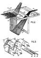
- Fig. 2 is a perspective diagrammatic view showing air ribboning and commingling components of the Fig. 1 apparatus.
- Fig. 3 is a perspective diagrammatic view of rollers of the Fig. 1 apparatus that are used for generating static electricity in a yarn to provide a flat opened ribbon according to the invention.
- commingling apparatus 10 in use commingling polyether ether ketone (PEEK) continuous multiple filament yarns 12 from freely rotatable supply rolls 14 and continuous multiple filament graphite yarn 16 from freely rotatable supply roll 18.
- PEEK polyether ether ketone
- apparatus 10 includes gathering guide 20, motor-driven pinch rollers 22, 24, three pretensioning bars 26, five motor-driven charge-inducing rollers 28 (1/32" thick virgin PTFE Teflon surface layers, available from DuPont, mounted on 4" steel support rollers), and ribboning bar 30.
- apparatus 10 On the path of travel for graphite yarn 16, apparatus 10 includes driven shaft 32, idler shaft 34, support rod 36, air curtain element 38 (a tube connected to a source of pressurized air and having a single row of downwardly directed holes along its length), and support rod 40. Downstream of support rod 40 and ribboning bar 30 are commingling bar 42, two free-wheeling rollers 43, atomizer 44 (for spraying sizing onto the filaments), and take-up unit 48 (including a traversing mechanism not shown) for wrapping the commingled yarn on take-up roll 49. Rollers 28 are electrically isolated, to permit the static charges to build up on the yarn. Downstream of rollers 28, ribboning bar 30, commingling bar 42, and rollers 43 are grounded, permitting bleeding of the charges.
- Pinch rolls 22, 24, driven shaft 32, and take-up unit 48 are driven by a common first drive system (not shown) to achieve the desired velocity of yarn through the apparatus.
- Rollers 28 are driven by a common second drive system (not shown) that provides variable speed from 0 to 200 feet per minute surface velocity, twice as fast as the typical yarn velocity of 33 meters (100 feet) per minute.
- the continuous multiple filament PEEK yarns 12 and graphite yarn 16 are separately opened up into flat opened ribbons, the flat opened ribbons are combined so as to have interleaving of different filaments, and the resulting combined flat ribbon is narrowed and wound up on the takeup roll.
- the graphite and PEEK yarns travel at approximately 100 feet per minute through apparatus 10.
- the three yarns pass through and are combined at guide 20. From there they are driven between pinch rollers 22, 24 and through pretensioning bars 26 to rollers 28. Pretensioning bars 26 assist providing desired tension in the PEEK yarns as they travel past and around rollers 28.
- the PEEK yarn cannot be opened up by application of an air curtain and, therefore, is opened up by generating a static charge on it through the use of rollers 28.
- Rollers 28 are driven at speeds to cause relative travel between the PEEK filaments and the Teflon surface. Rolls 28 develop a charge that is opposite that developed in the PEEK fibers, causing the fibers to be attracted to the rollers, and increasing the tension in fibers 12 as they pass through the five rollers 28.
- the charge applied to the PEEK filaments can be adjusted as necessary to provide the desired opening of the individual filaments, and the desired width of the flat ribbon that matches that of the flat ribbon of graphite yarns. From ribboning bar 30, the flat opened ribbon of PEEK yarns passes over commingling bar 42.
- Graphite yarn 16 travels from supply roll 18 between driven shaft 32 and idler shaft 34. Driven shaft 32 is driven at a speed equal to that of take-up roll 49 and pinch rolls 22, 24. The speed of driven shaft 32 can be adjusted if necessary to provide the loop between support rod 36 and support rod 40.
- the graphite yarn can be opened up into an open ribbon by the application of an air curtain, because the graphite fibers are not greatly attracted to each other.
- the pressurized curtain causes the loop to extend in the direction of air flow and the individual graphite filaments to separate so that the graphite yarn is in a flat opened ribbon state when it joins with the PEEK ribbon at the commingling bar 42.
- the opened ribbons of PEEK and graphite are joined together, and the different filaments are interleaved.
- the combined flat opened ribbon passes under and over free-wheeling rollers 43 and past atomizer 44, at which sizing is sprayed to cause the individual filaments to tend to adhere to each other.
- the charges have been bled sufficiently to permit the fibers to be in close proximity to each other.
- the commingled yarn has about a 3,8 cm (1 1/2") width, which is reduced to about 0,3 to 0,6 cm (1/8" to 1/4") by the guide of take-up unit 48, which wraps the commingled yarn on take-up roll 49.
- the commingled yarn can be stored indefinitely and used to produce woven, drapable, reinforced thermoplastic fabric on conventional equipment.
- heat and pressure is applied, and the PEEK flows around the reinforcing graphite fibers and bonds the graphite fibers together.
- the homogeneous nature of the commingled yarn provides intimate contact between the individual filaments of the component PEEK and graphite, thereby, providing improved wet out and bonding.
- the process is superior to other methods of assembling such yarns, for example, twisting and/or parallel winding, because the individual filaments of the component yarns are more homogeneously distributed throughout the resulting yarn. Because the yarn is commingled rather than layered, the component materials are more evenly distributed in the final product, resulting in better blending of reinforcing graphite fibers and resin matrix fibers, thereby producing superior products.
- the speed of travel through apparatus 10 has an effect on the quality of the product, in particular its homogeneity. It was found that as the speed was increased from 6,6 meters per sec (20 fpm) to around 23 meters per sec (70 fpm) there was not much noticeable effect on homogeneity; at around 23 meters per sec (70 fpm), improvements in quality were first noted, and increasing speed from 23 meters per sec (70 fpm) to over 33 meters per sec (100 fpm) resulted in further improvements in homogeneity. Continuing to increase speed above 33 meters per sec (100 fpm) should improve homogeneity even further. It is believed that the increased speed promotes parallel PEEK filaments during travel to the commingling bar. One factor permitting the high speeds is that there are no mechanical separating elements, e.g., comb teeth, which would limit speed and potentially damage filaments.
- sizing roll 45 (a roller partially located in a trough containing a sizing liquid) could be used to apply sizing to the yarns, and materials other than Teflon can be used in the static charge-inducing body.
Landscapes
- Engineering & Computer Science (AREA)
- Textile Engineering (AREA)
- Mechanical Engineering (AREA)
- Yarns And Mechanical Finishing Of Yarns Or Ropes (AREA)
Claims (29)
- Verfahren zum Mischen von zwei oder mehr verschiedenen kontinuierlichen Multifilamentgarnen (12, 16) zu einem einzigen Garn, enthaltend
kontinuierliches Zuführen getrennter erster und zweiter verschiedener kontinuierlicher Multifilamentgarne (12, 16),
Reiben des ersten Garns (12) gegen einen eine statische Ladung induzierenden Körper, der in einer elektrisch isolierenden Weise getragen ist, um auf das erste Garn (12) eine statische Ladung aufzubringen, die die Tendenz hat eine Trennung von einzelnen Multifilamenten des ersten Garns (12) zu bewirken,
dadurch gekennzeichnet, daß
der Körper eine mit variabler Geschwindigkeit dreh-angetriebene Walze (28) ist, die eine Tangentialgeschwindigkeit aufweist, die in der gleichen Richtung und schneller ist als die der Filamente des ersten Garns (12)
wobei alle Multifilamentstränge des ersten Garns (12) sich in der gleichen Richtung in bezug auf die Richtung der Rotation der Walze (28) vorwärtsbewegen,
und das Verfahren weiterhin enthält
Bewirken, daß das erste Garn (12) ein erstes geöffnetes Band bildet,
getrenntes Öffnen des zweiten Multifilamentgarns (16), um ein zweites geöffnetes Band zu bilden, und
Kombinieren der ersten und zweiten Bänder, um ein Mischen verschiedener einzelner Filamente zu bewirken,
wobei das erste Garn (12) nach dem Reiben gegen den die statische Ladung induzierenden Körper (28) und vor dem Kombinieren der ersten und zweiten Garne (12, 16) nicht durch irgendeine Antriebseinrichtung angetrieben wird. - Verfahren nach Anspruch 1, bei dem das erste Garn aus einem nichtleitenden Material gemacht ist, und das zweite Garn aus einem leitenden Material gemacht ist.
- Verfahren nach Anspruch 2, bei dem die ersten Fasern thermoplastische und die zweiten Fasern Kohlenstoffasern sind.
- Verfahren nach Anspruch 3, bei dem die thermoplastischen Fasern aus Polyether-Ether-Keton sind.
- Verfahren nach Anspruch 3, bei dem die thermoplastischen Fasern aus Polyphenylen-Sulfid sind.
- Verfahren nach Anspruch 1, bei dem das zweite Garn unter Verwendung eines Luftvorhangs, der auf eine zwischen zwei Abstützstäben hängende Schleife der Filamente gerichtet ist, zu den geöffnetem Band geöffnet wird.
- Verfahren nach Anspruch 1, bei dem das Kombinieren der geöffneten Bänder ein Zusammenbringen derselben über einer Vermischungsstange enthält.
- Verfahren nach Anspruch 7, bei dem das Öffnen des ersten Garns ein Vorbeibewegen unter Spannung um eine Bandbildungsstange enthält, um Filamente auszubreiten, die die statische Ladung darauf aufweisen.
- Verfahren nach Anspruch 1, das weiterhin ein Aufbringen eines Schlichtungsmittels auf das kombinierte geöffnete Band nach dem Kombinieren enthält.
- Verfahren nach Anspruch 9, das weiterhin ein Reduzieren der Breite des kombinierten geöffneten Bandes nach dem Aufbringen des Schlichtungsmittels enthält.
- Verfahren nach Anspruch 8, bei dem das Garn sich mit mehr als ungefähr 23 Meter (70 Fuß) pro Minute bewegt.
- Verfahren nach Anspruch 11, bei dem sich das Garn mit mehr als ungefähr 33 Meter (100 Fuß) pro Minute bewegt.
- Verfahren nach Anspruch 1, bei dem die Tangentialgeschwindigkeit zum Steuern der Spannung eingestellt wird.
- Verfahren nach Anspruch 1, bei dem die Tangentialgeschwindigkeit zum Steuern der Menge der statischen Ladung eingestellt wird.
- Verfahren nach Anspruch 1, bei dem das Reiben ein Reiben gegen eine Anzahl von mit variabler Geschwindigkeit dreh-angetriebenen Walzen (26) enthält, wobei das erste Garn (12) abwechselnd verschiedene Seiten der Walzen kontaktiert.
- Einrichtung zum Mischen von zwei oder mehr kontinuierlichen Multifilamentgarnen (12, 16) zu einem einzigen Garn, enthaltend
eine Zuführeinrichtung (14, 18) zum kontinuierlichen Zuführen getrennter erster und zweiter verschiedener kontinuierlicher Multifilamentgarne (12, 16),
einen eine statische Ladung induzierenden Körper, der in einer elektrisch isolierten Art getragen ist, um auf das von der Zuführeinrichtung (14) zugeführte erste Garn (12) eine statische Ladung aufzubringen, wenn das Garn sich an dem Körper vorbeibewegt und an diesem reibt, um eine Trennung einzelner Multifilamente des ersten Garns (12) zu bewirken,
dadurch gekennzeichnet, daß
der Körper eine mit variabler Geschwindigkeit dreh-angetriebene Walze (28) ist, die dazu vorgesehen ist eine Tangentialgeschwindigkeit aufzuweisen, die in der gleichen Richtung und schneller ist als die der Filamente des ersten Garns (12),
wobei alle Multifilamentstränge des ersten Garns sich in der gleichen Richtung in bezug auf die Richtung der Rotation der Walze (28) vorwärtsbewegen,
eine Einrichtung (30), um zu bewirken, daß das erste Garn (12) ein erstes geöffnetes Band bildet,
und wobei das Gerät weiterhin enthält
eine Einrichtung (38) zum getrennten Öffnen des zweiten Multifilamentgarns (16), um ein zweites geöffnetes Band zu bilden, und
eine Einrichtung (42) zum Kombinieren der ersten und zweiten Bänder, um ein Mischen verschiedener einzelner Filamente zu bewirken,
wobei die Einrichtung längs des Weges des ersten Garns (12) von dem die statische Ladung induzierenden Körper (28) zu der Einrichtung zum Kombinieren (42) keinerlei Antriebseinrichtung aufweist. - Einrichtung nach Anspruch 16, bei der die Einrichtung (38) zum getrennten Öffnen eine einen Luftvorhang erzeugende Einrichtung umfaßt, um das zweite Garn zu öffnen.
- Einrichtung nach Anspruch 16, bei der die Einrichtung zum Kombinieren (42) eine Vermischungsstange enthält, über welche sich die ersten und zweiten geöffneten Bänder bewegen.
- Einrichtung nach Anspruch 18, weiterhin enthaltend eine Bandbildungsstange (30) zwischen dem Körper (28) und der Vermischungsstange (42), um Filamente des ersten Garns (12) auszubreiten, die die darauf aufgebrachte Ladung aufweisen.
- Einrichtung nach Anspruch 19, weiterhin enthaltend einen Zerstäuber (44) zum Aufbringen eines Schlichtungsmittels auf das kombinierte geöffnete Band nach dem Verlassen der Vermischungsstange (42).
- Einrichtung nach Anspruch 19, weiterhin enthaltend eine Schlichtungswalze zum Aufbringen eines Schlichtungsmittels auf das kombinierte geöffnete Band nach dem Verlassen der Vermischungsstange.
- Einrichtung nach Anspruch 18, bei der die Vermischungsstange (42) geerdet ist.
- Einrichtung nach Anspruch 19, bei der die Vermischungsstange (42) und die Bandbildungsstange (30) geerdet sind.
- Einrichtung nach Anspruch 19, bei der die Einrichtung dazu vorgesehen ist zu bewirken, daß die Garne (12, 16) sich mit mehr als ungefähr 23 Meter (70 Fuß) pro Minute durch die Einrichtung bewegen.
- Einrichtung nach Anspruch 24, bei welcher die Einrichtung in der Lage ist zu bewirken, daß die Garne (12, 16) sich mit mehr als ungefähr 33 Meter (100 Fuß) pro Minute durch die Einrichtung bewegen.
- Einrichtung nach Anspruch 16, bei der das erste Garn aus nichtleitendem Material gemacht ist, und das zweite Garn aus leitenden Material gemacht ist.
- Einrichtung nach Anspruch 16, bei die Tangentialgeschwindigkeit zum Steuern der Spannung einstellbar ist.
- Einrichtung nach Anspruch 16, bei der die Tangentialgeschwindigkeit zum Steuern der Menge der statischen Ladung einstellbar ist.
- Einrichtung nach Anspruch 16, weiterhin enthaltend zusätzliche mit variabler Geschwindigkeit dreh-angetriebene Walzen (26), wobei das erste Garn (12) abwechselnd verschiedene Seiten der Walzen (26) kontaktiert.
Applications Claiming Priority (4)
| Application Number | Priority Date | Filing Date | Title |
|---|---|---|---|
| US2124887A | 1987-03-03 | 1987-03-03 | |
| US07/377,175 US5000807A (en) | 1987-03-03 | 1989-07-10 | Apparatus and method for commingling continuous multifilament yarns |
| CA002038542A CA2038542C (en) | 1989-07-10 | 1991-03-18 | Apparatus and method for commingling continuous multifilament yarns |
| JP3216726A JP2708978B2 (ja) | 1989-07-10 | 1991-03-19 | 連続マルチフィラメントヤーンを混合する装置と方法 |
Publications (2)
| Publication Number | Publication Date |
|---|---|
| EP0504445A1 EP0504445A1 (de) | 1992-09-23 |
| EP0504445B1 true EP0504445B1 (de) | 1995-12-27 |
Family
ID=27426843
Family Applications (1)
| Application Number | Title | Priority Date | Filing Date |
|---|---|---|---|
| EP91104188A Expired - Lifetime EP0504445B1 (de) | 1987-03-03 | 1991-03-18 | Gerät und Verfahren zum Mischen von kontinuierlichen Multifilamentgarnen |
Country Status (1)
| Country | Link |
|---|---|
| EP (1) | EP0504445B1 (de) |
Families Citing this family (1)
| Publication number | Priority date | Publication date | Assignee | Title |
|---|---|---|---|---|
| GB201604047D0 (en) | 2016-03-09 | 2016-04-20 | Coats Ltd J & P | Thread |
Family Cites Families (2)
| Publication number | Priority date | Publication date | Assignee | Title |
|---|---|---|---|---|
| EP0156599B1 (de) * | 1984-03-15 | 1988-11-09 | BASF Aktiengesellschaft | Mischungen aus Verbund-Kohlestoffasern und thermoplastischen Fasern |
| DE3730207A1 (de) * | 1987-09-09 | 1989-03-30 | Fritz Stahlecker | Verfahren zum verfestigen verstreckter faserbaender |
-
1991
- 1991-03-18 EP EP91104188A patent/EP0504445B1/de not_active Expired - Lifetime
Also Published As
| Publication number | Publication date |
|---|---|
| EP0504445A1 (de) | 1992-09-23 |
Similar Documents
| Publication | Publication Date | Title |
|---|---|---|
| US5000807A (en) | Apparatus and method for commingling continuous multifilament yarns | |
| US5241731A (en) | Apparatus for commingling continuous multifilament yarns | |
| RU2126367C1 (ru) | Способ формирования композитной нити и устройство для осуществления способа | |
| US5355567A (en) | Process for preparing engineered fiber blend | |
| US4159619A (en) | Method for producing novelty yarns | |
| EP0057583B1 (de) | Synthetisches Garn und garnähnliche Strukturen und Verfahren zur Herstellung derselben | |
| KR100601346B1 (ko) | 사를 방사, 연신, 및 권취하기 위한 방법 및 장치 | |
| US4997503A (en) | Filament winding apparatus and method | |
| EP0465917B1 (de) | Verfahren und Vorrichtung zur Herstellung glasfaserverstärker Matten | |
| TWI427201B (zh) | 製造複合線的方法及裝置 | |
| US5182839A (en) | Apparatus and method for commingling continuous multifilament yarns | |
| US3664115A (en) | Method of making a semi-continuous filament combination yarn | |
| EP0431439B1 (de) | Vorrichtung und Verfahren zur Herstellung einer Glasfasermatte | |
| EP0504445B1 (de) | Gerät und Verfahren zum Mischen von kontinuierlichen Multifilamentgarnen | |
| JPS61229535A (ja) | 繊維補強樹脂シ−トの製造方法及びその装置 | |
| US3444683A (en) | Manufacture of endless threadlike products of thermoplastic materials | |
| GB2115446A (en) | Yarn manufacturing method and apparatus | |
| US5639307A (en) | Fiber bundle coating apparatus | |
| US3175348A (en) | Process and apparatus for making bulked filament yarns | |
| US11846044B2 (en) | Device and method for producing fancy yarns | |
| US4403744A (en) | Method and apparatus for controlling strand tension during winding | |
| JPS61230929A (ja) | 繊維強化有機マトリクスからなる物体を支持体上への前記繊維の巻装によつて形成する方法及び該方法を実施するための装置 | |
| GB2051165A (en) | Composite Yarns | |
| JPH062970B2 (ja) | スラブヤ−ン及びその製造方法 | |
| GB2073792A (en) | Raised Yarn |
Legal Events
| Date | Code | Title | Description |
|---|---|---|---|
| PUAI | Public reference made under article 153(3) epc to a published international application that has entered the european phase |
Free format text: ORIGINAL CODE: 0009012 |
|
| AK | Designated contracting states |
Kind code of ref document: A1 Designated state(s): AT BE CH DE DK ES FR GB GR IT LI LU NL SE |
|
| 17P | Request for examination filed |
Effective date: 19930303 |
|
| 17Q | First examination report despatched |
Effective date: 19940510 |
|
| GRAA | (expected) grant |
Free format text: ORIGINAL CODE: 0009210 |
|
| AK | Designated contracting states |
Kind code of ref document: B1 Designated state(s): AT BE CH DE DK ES FR GB GR IT LI LU NL SE |
|
| PG25 | Lapsed in a contracting state [announced via postgrant information from national office to epo] |
Ref country code: BE Effective date: 19951227 Ref country code: IT Free format text: LAPSE BECAUSE OF FAILURE TO SUBMIT A TRANSLATION OF THE DESCRIPTION OR TO PAY THE FEE WITHIN THE PRESCRIBED TIME-LIMIT;WARNING: LAPSES OF ITALIAN PATENTS WITH EFFECTIVE DATE BEFORE 2007 MAY HAVE OCCURRED AT ANY TIME BEFORE 2007. THE CORRECT EFFECTIVE DATE MAY BE DIFFERENT FROM THE ONE RECORDED. Effective date: 19951227 Ref country code: CH Effective date: 19951227 Ref country code: AT Effective date: 19951227 Ref country code: GR Free format text: LAPSE BECAUSE OF FAILURE TO SUBMIT A TRANSLATION OF THE DESCRIPTION OR TO PAY THE FEE WITHIN THE PRESCRIBED TIME-LIMIT Effective date: 19951227 Ref country code: ES Free format text: THE PATENT HAS BEEN ANNULLED BY A DECISION OF A NATIONAL AUTHORITY Effective date: 19951227 Ref country code: NL Free format text: LAPSE BECAUSE OF FAILURE TO SUBMIT A TRANSLATION OF THE DESCRIPTION OR TO PAY THE FEE WITHIN THE PRESCRIBED TIME-LIMIT Effective date: 19951227 Ref country code: LI Effective date: 19951227 Ref country code: DK Effective date: 19951227 |
|
| REF | Corresponds to: |
Ref document number: 132210 Country of ref document: AT Date of ref document: 19960115 Kind code of ref document: T |
|
| REF | Corresponds to: |
Ref document number: 69115882 Country of ref document: DE Date of ref document: 19960208 |
|
| ET | Fr: translation filed | ||
| PG25 | Lapsed in a contracting state [announced via postgrant information from national office to epo] |
Ref country code: SE Effective date: 19960327 |
|
| PG25 | Lapsed in a contracting state [announced via postgrant information from national office to epo] |
Ref country code: LU Free format text: LAPSE BECAUSE OF NON-PAYMENT OF DUE FEES Effective date: 19960331 |
|
| NLV1 | Nl: lapsed or annulled due to failure to fulfill the requirements of art. 29p and 29m of the patents act | ||
| PLBE | No opposition filed within time limit |
Free format text: ORIGINAL CODE: 0009261 |
|
| STAA | Information on the status of an ep patent application or granted ep patent |
Free format text: STATUS: NO OPPOSITION FILED WITHIN TIME LIMIT |
|
| 26N | No opposition filed | ||
| REG | Reference to a national code |
Ref country code: GB Ref legal event code: IF02 |
|
| PGFP | Annual fee paid to national office [announced via postgrant information from national office to epo] |
Ref country code: GB Payment date: 20030319 Year of fee payment: 13 Ref country code: FR Payment date: 20030319 Year of fee payment: 13 |
|
| PGFP | Annual fee paid to national office [announced via postgrant information from national office to epo] |
Ref country code: DE Payment date: 20030331 Year of fee payment: 13 |
|
| PG25 | Lapsed in a contracting state [announced via postgrant information from national office to epo] |
Ref country code: GB Free format text: LAPSE BECAUSE OF NON-PAYMENT OF DUE FEES Effective date: 20040318 |
|
| PG25 | Lapsed in a contracting state [announced via postgrant information from national office to epo] |
Ref country code: DE Free format text: LAPSE BECAUSE OF NON-PAYMENT OF DUE FEES Effective date: 20041001 |
|
| GBPC | Gb: european patent ceased through non-payment of renewal fee |
Effective date: 20040318 |
|
| PG25 | Lapsed in a contracting state [announced via postgrant information from national office to epo] |
Ref country code: FR Free format text: LAPSE BECAUSE OF NON-PAYMENT OF DUE FEES Effective date: 20041130 |
|
| REG | Reference to a national code |
Ref country code: FR Ref legal event code: ST |