EP0504295B1 - Drehautomat mit unbeweglichem spindelstock und aufbearbeitungsspindel - Google Patents
Drehautomat mit unbeweglichem spindelstock und aufbearbeitungsspindel Download PDFInfo
- Publication number
- EP0504295B1 EP0504295B1 EP91901509A EP91901509A EP0504295B1 EP 0504295 B1 EP0504295 B1 EP 0504295B1 EP 91901509 A EP91901509 A EP 91901509A EP 91901509 A EP91901509 A EP 91901509A EP 0504295 B1 EP0504295 B1 EP 0504295B1
- Authority
- EP
- European Patent Office
- Prior art keywords
- tool
- turret
- spindle
- carried
- tool holder
- Prior art date
- Legal status (The legal status is an assumption and is not a legal conclusion. Google has not performed a legal analysis and makes no representation as to the accuracy of the status listed.)
- Expired - Lifetime
Links
- 238000003754 machining Methods 0.000 claims abstract description 29
- 238000005553 drilling Methods 0.000 claims description 15
- 238000006073 displacement reaction Methods 0.000 description 6
- 238000011084 recovery Methods 0.000 description 5
- 230000005540 biological transmission Effects 0.000 description 1
- 238000010276 construction Methods 0.000 description 1
- 238000004519 manufacturing process Methods 0.000 description 1
- 239000002994 raw material Substances 0.000 description 1
- 239000002699 waste material Substances 0.000 description 1
Images



Classifications
-
- B—PERFORMING OPERATIONS; TRANSPORTING
- B23—MACHINE TOOLS; METAL-WORKING NOT OTHERWISE PROVIDED FOR
- B23Q—DETAILS, COMPONENTS, OR ACCESSORIES FOR MACHINE TOOLS, e.g. ARRANGEMENTS FOR COPYING OR CONTROLLING; MACHINE TOOLS IN GENERAL CHARACTERISED BY THE CONSTRUCTION OF PARTICULAR DETAILS OR COMPONENTS; COMBINATIONS OR ASSOCIATIONS OF METAL-WORKING MACHINES, NOT DIRECTED TO A PARTICULAR RESULT
- B23Q39/00—Metal-working machines incorporating a plurality of sub-assemblies, each capable of performing a metal-working operation
- B23Q39/04—Metal-working machines incorporating a plurality of sub-assemblies, each capable of performing a metal-working operation the sub-assemblies being arranged to operate simultaneously at different stations, e.g. with an annular work-table moved in steps
- B23Q39/048—Metal-working machines incorporating a plurality of sub-assemblies, each capable of performing a metal-working operation the sub-assemblies being arranged to operate simultaneously at different stations, e.g. with an annular work-table moved in steps the work holder of a work station transfers directly its workpiece to the work holder of a following work station
-
- Y—GENERAL TAGGING OF NEW TECHNOLOGICAL DEVELOPMENTS; GENERAL TAGGING OF CROSS-SECTIONAL TECHNOLOGIES SPANNING OVER SEVERAL SECTIONS OF THE IPC; TECHNICAL SUBJECTS COVERED BY FORMER USPC CROSS-REFERENCE ART COLLECTIONS [XRACs] AND DIGESTS
- Y10—TECHNICAL SUBJECTS COVERED BY FORMER USPC
- Y10T—TECHNICAL SUBJECTS COVERED BY FORMER US CLASSIFICATION
- Y10T29/00—Metal working
- Y10T29/51—Plural diverse manufacturing apparatus including means for metal shaping or assembling
- Y10T29/5104—Type of machine
- Y10T29/5109—Lathe
- Y10T29/5114—Lathe and tool
-
- Y—GENERAL TAGGING OF NEW TECHNOLOGICAL DEVELOPMENTS; GENERAL TAGGING OF CROSS-SECTIONAL TECHNOLOGIES SPANNING OVER SEVERAL SECTIONS OF THE IPC; TECHNICAL SUBJECTS COVERED BY FORMER USPC CROSS-REFERENCE ART COLLECTIONS [XRACs] AND DIGESTS
- Y10—TECHNICAL SUBJECTS COVERED BY FORMER USPC
- Y10T—TECHNICAL SUBJECTS COVERED BY FORMER US CLASSIFICATION
- Y10T82/00—Turning
- Y10T82/25—Lathe
- Y10T82/2502—Lathe with program control
- Y10T82/2506—And tool turret
-
- Y—GENERAL TAGGING OF NEW TECHNOLOGICAL DEVELOPMENTS; GENERAL TAGGING OF CROSS-SECTIONAL TECHNOLOGIES SPANNING OVER SEVERAL SECTIONS OF THE IPC; TECHNICAL SUBJECTS COVERED BY FORMER USPC CROSS-REFERENCE ART COLLECTIONS [XRACs] AND DIGESTS
- Y10—TECHNICAL SUBJECTS COVERED BY FORMER USPC
- Y10T—TECHNICAL SUBJECTS COVERED BY FORMER US CLASSIFICATION
- Y10T82/00—Turning
- Y10T82/25—Lathe
- Y10T82/2514—Lathe with work feeder or remover
Definitions
- the present invention relates to a fixed head turning lathe comprising a main spindle carrying a workpiece, a first main tool turret and a second main tool turret, said first main tool turret being movable along two orthogonal axes.
- the second main tool turret carrying a take-up spindle arranged to support a part at least partially machined and previously carried by the main spindle, this take-up spindle being arranged to present this part at least partially machined at least one tool carried by said auxiliary tool turret, the first main tool turret carrying at least one tool for machining the workpiece and at least one cutting tool, the second main tool turret carrying at least one tool for machining the workpiece carried by the main spindle , the machining tool carried by the second main tool turret being able to be a drilling or fixed boring tool, the auxiliary tool turret carrying at least one tool for machining the partially machined part carried by a recovery spindle
- lathes Numerous types of lathes are already known comprising a main turret carrying various tools for machining a part and a secondary turret carrying at least one tool, generally of boring or drilling to simultaneously machine this part on the free face, in an axial direction .
- German patent application DE-A-3,626,324 which relates to a two-turret lathe and an auxiliary turret.
- the auxiliary turret is fixed, arranged opposite the main turrets, which does not allow a frontal arrangement nor a simultaneous machining of parts supported by a recovery spindle.
- the present invention proposes to overcome these drawbacks by making a lathe capable of machining the two opposite faces of a mechanical part, while retaining a frontal arrangement of the two main turrets, which guarantees particularly easy access.
- the lathe according to the invention is characterized in that the auxiliary tool-holder turret is carried on the support of the second main turret, and in that the second main tool-holder turret carries an axially movable carriage according to axis parallel to the axis of the main spindle, this carriage carrying at least one machining tool arranged for drilling or boring a part driven in rotation by the take-up spindle.
- the tool carried by the second main tool turret is arranged to work on a part carried by the main spindle and the tool carried by the auxiliary tool turret is arranged to work simultaneously on a part carried by the rework pin.
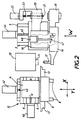
- the lathe as shown, essentially comprises a main spindle 10 carrying a workpiece 11 to be machined, driven in rotation about the axis of this spindle. It also comprises a first main turret 12 which carries one or more tools 13 which can be brought into a suitable position to ensure the machining of the part 11.
- the turret is integral with a body 14 in which is mounted its axis of rotation and which is carried by a support 15 arranged to allow the movements of this turret along two perpendicular axes X and Y.
- the support 15 consists of a movable carriage 9 which can slide in the direction defined by the Y axis on two parallel slides 8, mounted on the frame 7 of the lathe and two slides 6 integral with the movable carriage 9 and which allow the body 14 and consequently the main turret 12 to move along the X axis.
- It also comprises a second main turret 16 on which is mounted at least one tool 17, which is a boring or drilling tool arranged to work the free face of the part 11.
- This second main turret 16 is integral with a body 18 which is movable in translation along an axis W.
- this second main turret 16 and its body 18 are carried by a support 5 which consists of a movable carriage 4 which can slide in the direction defined by the axis W on two parallel slides 3 which are also mounted on the frame 7 of the lathe.
- the displacement along the X axis of the first main turret is obtained by means of a drive motor 40 of an endless screw 41 coupled to the body 14 of the turret 12.
- the displacement along the Y axis of this turret is obtained thanks to a drive motor 42 of a screw 43 coupled to the carriage 9.
- the displacement along the axis W of the second main turret 16 is obtained thanks to a drive motor 44 of a screw 45 coupled to the carriage 5 It is understood that these displacements could be achieved by other known mechanical means, in particular by hydraulic cylinders.
- this second main turret 16 can pivot by an angle of 180 ° to allow the drilling tool, bore to come into the position shown in Figure 2, and to move to a rest position at 180 ° the previous one to allow a take-up spindle 19, also carried by this turret, to take over the part 11, when it has been machined by the tools 13 carried by the first main turret 12.
- the means for driving said first and second main turrets in rotation are not shown in the figures.
- these figures show the drive means of the take-up spindle 19 which is rotatable to allow the machining of the rear face of the part 11 previously machined on its front face by the tool 17.
- These drive means comprise a motor 46 mounted in the body 18 and an appropriate transmission 47.
- the lathe shown carries an auxiliary tool turret 20 arranged to carry at least one tool 21 whose role is to ensure machining on the cutting face of the part 11.
- the auxiliary turret 19 is rigidly fixed to the body 18 of the second main turret 16, so that it moves parallel to the axis W and at the same time as it.
- a motor 22 cooperates with a screw 23 for axially displacing the tool 21.
- the tool 21 is mounted on a turret which carries at least three drilling or boring tools which can be brought into the working position following a rotationally indexed displacement of this turret.
- the tools are in principle fixed, but could also be rotating. In the latter case, they are rotated by an onboard motor.
- the main spindle is rotated by a drive motor M.
- a drive motor M we work directly on the raw material bar, and the advance of this bar can be performed by a special device known per se which is associated with the lathe.
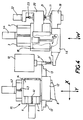
- Figure 3 shows more particularly a first work sequence of the lathe shown.
- the part which has been previously machined by the tool 13 carried by the first main turret, and simultaneously by the drilling or boring tool 17, is cut by a cutting tool 13 'carried by this same turret and then taken up by the recovery spindle 19.
- the drilling or reaming tool 17 of the second main turret is in a rest position, after the second main turret 16 has pivoted by an angle of 180 ° around the axis W of its body 18.
- this tool was in place opposite part 11 and provided drilling and / or reaming operations while other machining operations were carried out by the tool (s) 13.
- this construction has the advantage of having a frontal configuration, this which reduces clutter, facilitates access and improves the ease of use of the machine.
- FIG. 5 illustrates a variant according to which the auxiliary turret is arranged differently from that of the previous embodiment example.
- the body 18 of the second main turret 16 carries a carriage 30, movable in translation along the axis T.
- This carriage serves as a support for a turret 31, arranged to pivot around an axis R perpendicular to the axis T.
- This turret can be of the hexagonal type and can for example carry six tools 32 capable of being brought respectively into position for machining the cutting face of a part 11 'previously machined on the other face.
- the displacement along the axis T is effected by means of an endless screw 33 driven by a motor 34.
- a particularly interesting advantage of these embodiments is that the adjustments can be made easily, access being provided on three sides of the machine thanks to the existence of a cover (not shown) which can be lifted vertically.
Landscapes
- Engineering & Computer Science (AREA)
- Mechanical Engineering (AREA)
- Turning (AREA)
- Toys (AREA)
- Arc-Extinguishing Devices That Are Switches (AREA)
Claims (2)
- Abstechdrehbank mit Spindelstock bestehend aus einer, ein zu bearbeitendes Werkstück (11) tragenden, Hauptspindel (10), einem ersten Haupt-Werkzeugrevolverkopf (12) und einem zweiten Haupt-Werkzeugrevolverkopf (16), wobei der erste Haupt-Werkzeugrevolverkopf (12) in zwei rechtwinklig zueinander stehenden Achsen bewegbar ist, wovon eine parallel zur Achse der Hauptspindel (10) liegt und der zweite Haupt-Werkzeugrevolverkopf (16) in mindestens einer Achse parallel zu derjenigen der Hauptspindel (10) liegt, einem in einer Achse parallel zu derjenigen der Hauptspindel (10) bewegbaren Hilfs-Werkzeugrevolverkopf (20), wobei der zweite Haupt-Werkzeugrevolverkopf (16) eine Aufnahmespindel (19) trägt, die dazu dient, ein wenigstens teilweise bearbeitetes und vorher von der Hauptspindel (10) getragenes Werkstück (11) aufzunehmen, und diese Aufnahmespindel so ausgeführt ist, daß sie dieses wenigstens teilweise bearbeitete Werkstück für mindestens ein von dem Hilfs-Werkzeugrevolverkopf (20) getragenes Werkzeug (21) bereithält, wobei der erste Haupt-Werkzeugrevolverkopf (12) mindestens ein Werkzeug zur spanenden Bearbeitung des Werkstückes und mindestens ein Abstechwerkzeug trägt, und der zweite Haupt-Werkzeugrevolverkopf (16) mindestens ein Werkzeug zur spanenden Bearbeitung des zu bearbeitenden und von der Hauptspindel (10) getragenen Werkstückes trägt, wobei das von dem zweiten Haupt-Werkzeugrevolverkopf (16) getragene Werkzeug ein feststehendes Werkzeug zum Bohren oder zum Ausdrehen sein kann, und der Hilfs-Werkzeugrevolverkopf (20) mindestens ein Werkzeug zur spanenden Bearbeitung des teilweise bearbeiteten Werkstückes trägt, wobei letzteres von einer Aufnahmespindel (19) gehalten und durch diese in Drehung versetzt ist, wobei das von dem Hilfs-Werkzeugrevolverkopf (20) gehaltene Werkzeug zur spanenden Bearbeitung ein Werkzeug zum Bohren oder zum Ausdrehen sein kann und das Bearbeitungswerkzeug und die von dem zweiten Haupt-Werkzeugrevolverkopf (16) getragene Aufnahmespindel (19) zueinander um 180° versetzt angeordnet sind,
dadurch gekennzeichnet, daß der Hilfs-Werkzeugrevolverkopf (20) auf dem Support für den zweiten Haupt-Werkzeugrevolverkopf (16) befestigt ist und daß der zweite Haupt-Werkzeugrevolverkopf (16) einen, parallel zur Achse der Hauptspindel gemäß Achse (T) axial bewegbaren Schlitten (30) trägt, wobei dieser Schlitten mindestens ein Bearbeitungswerkzeug (32) trägt, welches dazu dient, ein durch die Aufnahmespindel (19) in Drehung versetztes Werkstück zu bohren oder auszudrehen. - Abstechdrehbank nach Anspruch 1,
dadurch gekennzeichnet, daß das von dem zweiten Haupt-Werkzeugrevolverkopf (16) aufgenommene Werkzeug (17) so ausgeführt ist, daß es an einem, von der Hauptspindel (10) getragenen Werkstück (11) arbeiten kann und daß das von dem Hilfs-Werkzeugrevolverkopf (20) gehaltene Werkzeug (21) so ausgeführt ist, daß es gleichzeitig an einem von der Aufnahmespindel (19) gehaltenen Werkstück (11') arbeiten kann.
Applications Claiming Priority (3)
| Application Number | Priority Date | Filing Date | Title |
|---|---|---|---|
| FR8916369A FR2655580B1 (fr) | 1989-12-07 | 1989-12-07 | Tour de decolletage a poupee fixe et broche de reprise. |
| FR8916369 | 1989-12-07 | ||
| PCT/FR1990/000887 WO1991008852A1 (fr) | 1989-12-07 | 1990-12-06 | Tour de decolletage a poupee fixe et broche de reprise |
Publications (2)
| Publication Number | Publication Date |
|---|---|
| EP0504295A1 EP0504295A1 (de) | 1992-09-23 |
| EP0504295B1 true EP0504295B1 (de) | 1994-09-14 |
Family
ID=9388382
Family Applications (1)
| Application Number | Title | Priority Date | Filing Date |
|---|---|---|---|
| EP91901509A Expired - Lifetime EP0504295B1 (de) | 1989-12-07 | 1990-12-06 | Drehautomat mit unbeweglichem spindelstock und aufbearbeitungsspindel |
Country Status (6)
| Country | Link |
|---|---|
| US (1) | US5282300A (de) |
| EP (1) | EP0504295B1 (de) |
| AT (1) | ATE111387T1 (de) |
| DE (2) | DE9018061U1 (de) |
| FR (1) | FR2655580B1 (de) |
| WO (1) | WO1991008852A1 (de) |
Cited By (1)
| Publication number | Priority date | Publication date | Assignee | Title |
|---|---|---|---|---|
| DE19515044A1 (de) * | 1995-04-24 | 1996-10-31 | Traub Ag | Drehmaschine für vorder- und rückseitige Werkstückbearbeitung |
Families Citing this family (10)
| Publication number | Priority date | Publication date | Assignee | Title |
|---|---|---|---|---|
| DE4236173A1 (de) * | 1992-10-27 | 1994-04-28 | Heidelberger Druckmasch Ag | Werkzeugmaschine zur spanabhebenden Bearbeitung |
| DE9306460U1 (de) * | 1993-04-29 | 1993-09-16 | Index-Werke Gmbh & Co Kg Hahn & Tessky, 73730 Esslingen | Drehautomat |
| US5885199A (en) * | 1996-02-06 | 1999-03-23 | Shao; Wenyuan | Compact machining center for multifunction |
| US6049965A (en) * | 1997-07-31 | 2000-04-18 | Liberty Research Company, Inc. | Method and apparatus for machining a workpiece |
| DE19911411A1 (de) * | 1999-03-15 | 2000-09-28 | Boehringer Werkzeugmaschinen | Werkzeugmaschine |
| WO2002024386A1 (fr) * | 2000-09-22 | 2002-03-28 | Citizen Watch Co., Ltd. | Tour automatique |
| DE10048291A1 (de) * | 2000-09-29 | 2002-05-02 | Traub Drehmaschinen Gmbh | Drehmaschine |
| JP4833887B2 (ja) * | 2007-02-26 | 2011-12-07 | オークマ株式会社 | タレット刃物台及び工作機械 |
| CN103611961B (zh) * | 2013-11-25 | 2016-03-02 | 苏州康菲特自动化科技有限公司 | 一种滑轨式刀架 |
| EP2963305B1 (de) * | 2014-06-30 | 2019-04-17 | Aktiebolaget SKF | Verfahren zur herstellung einer hohlwalze, durch solch ein verfahren herstellbare hohlwalze und wälzlager mit solch einer walze |
Family Cites Families (9)
| Publication number | Priority date | Publication date | Assignee | Title |
|---|---|---|---|---|
| GB744296A (en) * | 1952-06-11 | 1956-02-01 | Guy Worrell | Single spindle automatic turret lathe |
| AT204347B (de) * | 1956-08-15 | 1959-07-10 | Tornos Sa Fabrique De Machine | Automatische Drehbank |
| US3821835A (en) * | 1972-08-17 | 1974-07-02 | Cincinnati Milacron Heald | Machine tool |
| US4413539A (en) * | 1979-10-31 | 1983-11-08 | Citizen Watch Company Limited | Numerically controlled lathe |
| US4597155A (en) * | 1981-03-20 | 1986-07-01 | The Olofsson Corporation | Boring machine with work-handling tool turret |
| DE8313200U1 (de) * | 1983-05-04 | 1983-09-15 | Index-Werke Kg Hahn & Tessky, 7300 Esslingen | Revolver-drehautomat |
| DE3626324A1 (de) * | 1986-08-02 | 1988-02-04 | Pittler Ag Maschf | Doppelspindel-drehmaschine |
| JPS63229201A (ja) * | 1987-03-17 | 1988-09-26 | Fujitsu Ltd | タレツト旋盤 |
| US4949443A (en) * | 1988-06-29 | 1990-08-21 | Tatsuhiko Saruwatari | Numerically controlled lathe |
-
1989
- 1989-12-07 FR FR8916369A patent/FR2655580B1/fr not_active Expired - Fee Related
-
1990
- 1990-12-06 DE DE9018061U patent/DE9018061U1/de not_active Expired - Lifetime
- 1990-12-06 WO PCT/FR1990/000887 patent/WO1991008852A1/fr not_active Ceased
- 1990-12-06 AT AT91901509T patent/ATE111387T1/de active
- 1990-12-06 US US07/853,770 patent/US5282300A/en not_active Expired - Fee Related
- 1990-12-06 DE DE69012585T patent/DE69012585T2/de not_active Expired - Fee Related
- 1990-12-06 EP EP91901509A patent/EP0504295B1/de not_active Expired - Lifetime
Cited By (1)
| Publication number | Priority date | Publication date | Assignee | Title |
|---|---|---|---|---|
| DE19515044A1 (de) * | 1995-04-24 | 1996-10-31 | Traub Ag | Drehmaschine für vorder- und rückseitige Werkstückbearbeitung |
Also Published As
| Publication number | Publication date |
|---|---|
| DE9018061U1 (de) | 1994-08-18 |
| ATE111387T1 (de) | 1994-09-15 |
| WO1991008852A1 (fr) | 1991-06-27 |
| DE69012585T2 (de) | 1995-03-09 |
| FR2655580A1 (fr) | 1991-06-14 |
| DE69012585D1 (de) | 1994-10-20 |
| FR2655580B1 (fr) | 1994-05-27 |
| US5282300A (en) | 1994-02-01 |
| EP0504295A1 (de) | 1992-09-23 |
Similar Documents
| Publication | Publication Date | Title |
|---|---|---|
| EP0504295B1 (de) | Drehautomat mit unbeweglichem spindelstock und aufbearbeitungsspindel | |
| EP0068952B1 (de) | Werkzeugmaschinen mit hoher Produktivität | |
| FR2563454A1 (fr) | Machine-outil multi-fonctions a deux broches | |
| CH636543A5 (fr) | Machine-outil comprenant deux broches coaxiales opposees. | |
| FR2565139A1 (fr) | Machine-outil a deux broches porte-piece | |
| FR2743015A1 (fr) | Machine a portique mobile avec des montants mobiles l'un par rapport a l'autre | |
| EP0473747B1 (de) | Werkzeugmaschine, insbesondere für dekolletieren | |
| FR2518002A1 (fr) | Tete multiple pour machine-outil a tetes multiples interchangeables | |
| EP0627969B1 (de) | Verfahren und vorrichtung zum wälzschälen | |
| EP1509361B1 (de) | Mehrachsiges bearbeitungszentrum mit einer werkstückspindel | |
| EP0936027B1 (de) | Bearbeitungsvorrichtung zum stirnseitigen Bearbeiten in einer Werkzeugmaschine | |
| FR2518460A1 (fr) | Dispositif de gravure pour l'usinage ornemental continu de chaines et/ou articles similaires | |
| FR2588793A1 (fr) | Installation flexible d'usinage | |
| FR2568802A1 (fr) | Tete multibroches pour machine-outil, notamment pour ensemble d'usinage a tetes interchangeables | |
| FR2564762A1 (fr) | Moyen d'indexage automatique d'une plaquette rapportee d'un outil de coupe | |
| FR2504037A1 (fr) | Centre de tournage a commande numerique permettant des operations de fraisage | |
| CH673607A5 (en) | Multipurpose machine tool - with flexibility enhanced by using large number of its working axes | |
| EP1726389B1 (de) | Werkzeugmaschine mit mobiler Führungsbuchse für die Herstellung von Teilen durch Abstechen | |
| EP0591033B1 (de) | Werkzeughalter für innere Bearbeitung | |
| FR2651708A1 (fr) | Dispositif changeur d'outils pour machine-outil. | |
| EP0007512B1 (de) | Bohrer mit Wendeplatten | |
| FR2631864A1 (en) | Multi-function machining head for machine tools | |
| FR2524360A1 (fr) | Machine-outil universelle avec une pluralite de postes d'usinage, constituant un centre d'usinage | |
| EP1433567A1 (de) | Einrichtung zur Befestigung eines mindestens ein Werkzeug stützenden Kopfes an einer Spindel einer Werkzeugmaschine | |
| EP3530386A1 (de) | Drehmaschine mit numerischer steuerung |
Legal Events
| Date | Code | Title | Description |
|---|---|---|---|
| PUAI | Public reference made under article 153(3) epc to a published international application that has entered the european phase |
Free format text: ORIGINAL CODE: 0009012 |
|
| 17P | Request for examination filed |
Effective date: 19920513 |
|
| AK | Designated contracting states |
Kind code of ref document: A1 Designated state(s): AT BE CH DE FR GB IT LI LU NL SE |
|
| 17Q | First examination report despatched |
Effective date: 19931029 |
|
| RAP1 | Party data changed (applicant data changed or rights of an application transferred) |
Owner name: K'MX TECHNOLOGIE S.A. |
|
| GRAA | (expected) grant |
Free format text: ORIGINAL CODE: 0009210 |
|
| AK | Designated contracting states |
Kind code of ref document: B1 Designated state(s): AT BE CH DE FR GB IT LI LU NL SE |
|
| PG25 | Lapsed in a contracting state [announced via postgrant information from national office to epo] |
Ref country code: NL Effective date: 19940914 Ref country code: AT Effective date: 19940914 |
|
| REF | Corresponds to: |
Ref document number: 111387 Country of ref document: AT Date of ref document: 19940915 Kind code of ref document: T |
|
| REF | Corresponds to: |
Ref document number: 69012585 Country of ref document: DE Date of ref document: 19941020 |
|
| ITF | It: translation for a ep patent filed | ||
| PG25 | Lapsed in a contracting state [announced via postgrant information from national office to epo] |
Ref country code: SE Effective date: 19941214 |
|
| PG25 | Lapsed in a contracting state [announced via postgrant information from national office to epo] |
Ref country code: LU Free format text: LAPSE BECAUSE OF NON-PAYMENT OF DUE FEES Effective date: 19941231 |
|
| GBT | Gb: translation of ep patent filed (gb section 77(6)(a)/1977) |
Effective date: 19941213 |
|
| NLV1 | Nl: lapsed or annulled due to failure to fulfill the requirements of art. 29p and 29m of the patents act | ||
| PLBE | No opposition filed within time limit |
Free format text: ORIGINAL CODE: 0009261 |
|
| STAA | Information on the status of an ep patent application or granted ep patent |
Free format text: STATUS: NO OPPOSITION FILED WITHIN TIME LIMIT |
|
| 26N | No opposition filed | ||
| PGFP | Annual fee paid to national office [announced via postgrant information from national office to epo] |
Ref country code: GB Payment date: 19971127 Year of fee payment: 8 |
|
| PGFP | Annual fee paid to national office [announced via postgrant information from national office to epo] |
Ref country code: DE Payment date: 19971206 Year of fee payment: 8 |
|
| PGFP | Annual fee paid to national office [announced via postgrant information from national office to epo] |
Ref country code: FR Payment date: 19971224 Year of fee payment: 8 |
|
| PGFP | Annual fee paid to national office [announced via postgrant information from national office to epo] |
Ref country code: BE Payment date: 19980115 Year of fee payment: 8 |
|
| PGFP | Annual fee paid to national office [announced via postgrant information from national office to epo] |
Ref country code: CH Payment date: 19980324 Year of fee payment: 8 |
|
| REG | Reference to a national code |
Ref country code: FR Ref legal event code: TP |
|
| PG25 | Lapsed in a contracting state [announced via postgrant information from national office to epo] |
Ref country code: GB Free format text: LAPSE BECAUSE OF NON-PAYMENT OF DUE FEES Effective date: 19981206 |
|
| PG25 | Lapsed in a contracting state [announced via postgrant information from national office to epo] |
Ref country code: LI Free format text: LAPSE BECAUSE OF NON-PAYMENT OF DUE FEES Effective date: 19981231 Ref country code: CH Free format text: LAPSE BECAUSE OF NON-PAYMENT OF DUE FEES Effective date: 19981231 Ref country code: BE Free format text: LAPSE BECAUSE OF NON-PAYMENT OF DUE FEES Effective date: 19981231 |
|
| BERE | Be: lapsed |
Owner name: S.A. K'MX TECHNOLOGIE Effective date: 19981231 |
|
| GBPC | Gb: european patent ceased through non-payment of renewal fee |
Effective date: 19981206 |
|
| REG | Reference to a national code |
Ref country code: CH Ref legal event code: PL |
|
| PG25 | Lapsed in a contracting state [announced via postgrant information from national office to epo] |
Ref country code: FR Free format text: LAPSE BECAUSE OF NON-PAYMENT OF DUE FEES Effective date: 19990831 |
|
| REG | Reference to a national code |
Ref country code: FR Ref legal event code: ST |
|
| PG25 | Lapsed in a contracting state [announced via postgrant information from national office to epo] |
Ref country code: DE Free format text: LAPSE BECAUSE OF NON-PAYMENT OF DUE FEES Effective date: 19991001 |
|
| PG25 | Lapsed in a contracting state [announced via postgrant information from national office to epo] |
Ref country code: IT Free format text: LAPSE BECAUSE OF NON-PAYMENT OF DUE FEES;WARNING: LAPSES OF ITALIAN PATENTS WITH EFFECTIVE DATE BEFORE 2007 MAY HAVE OCCURRED AT ANY TIME BEFORE 2007. THE CORRECT EFFECTIVE DATE MAY BE DIFFERENT FROM THE ONE RECORDED. Effective date: 20051206 |