EP0504203B1 - Methode und vorrichtung zur durchführung eines gas-flüssigkeit-kontaktes - Google Patents
Methode und vorrichtung zur durchführung eines gas-flüssigkeit-kontaktes Download PDFInfo
- Publication number
- EP0504203B1 EP0504203B1 EP91900143A EP91900143A EP0504203B1 EP 0504203 B1 EP0504203 B1 EP 0504203B1 EP 91900143 A EP91900143 A EP 91900143A EP 91900143 A EP91900143 A EP 91900143A EP 0504203 B1 EP0504203 B1 EP 0504203B1
- Authority
- EP
- European Patent Office
- Prior art keywords
- gas
- impeller
- shroud
- gas stream
- openings
- Prior art date
- Legal status (The legal status is an assumption and is not a legal conclusion. Google has not performed a legal analysis and makes no representation as to the accuracy of the status listed.)
- Expired - Lifetime
Links
- 239000007788 liquid Substances 0.000 title claims abstract description 86
- 238000000034 method Methods 0.000 title claims description 57
- 238000006243 chemical reaction Methods 0.000 claims abstract description 39
- 239000000126 substance Substances 0.000 claims abstract description 16
- 230000000694 effects Effects 0.000 claims abstract description 13
- 238000000926 separation method Methods 0.000 claims abstract description 12
- 239000007791 liquid phase Substances 0.000 claims description 22
- 239000007787 solid Substances 0.000 claims description 11
- 239000012071 phase Substances 0.000 claims description 10
- 239000000463 material Substances 0.000 claims description 8
- 239000012298 atmosphere Substances 0.000 claims description 7
- 239000003795 chemical substances by application Substances 0.000 claims description 4
- 238000005201 scrubbing Methods 0.000 claims description 4
- 239000011236 particulate material Substances 0.000 claims description 3
- 238000013022 venting Methods 0.000 claims 1
- 239000007789 gas Substances 0.000 abstract description 185
- RWSOTUBLDIXVET-UHFFFAOYSA-N Dihydrogen sulfide Chemical compound S RWSOTUBLDIXVET-UHFFFAOYSA-N 0.000 abstract description 81
- 229910000037 hydrogen sulfide Inorganic materials 0.000 abstract description 79
- 238000005188 flotation Methods 0.000 abstract description 35
- QVGXLLKOCUKJST-UHFFFAOYSA-N atomic oxygen Chemical compound [O] QVGXLLKOCUKJST-UHFFFAOYSA-N 0.000 abstract description 16
- 239000001301 oxygen Substances 0.000 abstract description 16
- 229910052760 oxygen Inorganic materials 0.000 abstract description 16
- 238000007254 oxidation reaction Methods 0.000 abstract description 10
- 230000003647 oxidation Effects 0.000 abstract description 9
- 229910052723 transition metal Inorganic materials 0.000 abstract description 8
- 150000003624 transition metals Chemical class 0.000 abstract description 8
- 238000012546 transfer Methods 0.000 abstract description 3
- 239000012265 solid product Substances 0.000 abstract 1
- RAHZWNYVWXNFOC-UHFFFAOYSA-N Sulphur dioxide Chemical group O=S=O RAHZWNYVWXNFOC-UHFFFAOYSA-N 0.000 description 60
- NINIDFKCEFEMDL-UHFFFAOYSA-N Sulfur Chemical compound [S] NINIDFKCEFEMDL-UHFFFAOYSA-N 0.000 description 40
- 239000011593 sulfur Substances 0.000 description 36
- 229910052717 sulfur Inorganic materials 0.000 description 36
- 230000008569 process Effects 0.000 description 30
- 239000002245 particle Substances 0.000 description 22
- 239000002609 medium Substances 0.000 description 21
- 239000002002 slurry Substances 0.000 description 18
- 239000003054 catalyst Substances 0.000 description 17
- 239000012429 reaction media Substances 0.000 description 15
- 239000000243 solution Substances 0.000 description 14
- 239000012736 aqueous medium Substances 0.000 description 13
- XEEYBQQBJWHFJM-UHFFFAOYSA-N Iron Chemical compound [Fe] XEEYBQQBJWHFJM-UHFFFAOYSA-N 0.000 description 12
- 239000007864 aqueous solution Substances 0.000 description 10
- 239000013522 chelant Substances 0.000 description 10
- 238000012360 testing method Methods 0.000 description 9
- KCXVZYZYPLLWCC-UHFFFAOYSA-N EDTA Chemical group OC(=O)CN(CC(O)=O)CCN(CC(O)=O)CC(O)=O KCXVZYZYPLLWCC-UHFFFAOYSA-N 0.000 description 7
- HEMHJVSKTPXQMS-UHFFFAOYSA-M Sodium hydroxide Chemical compound [OH-].[Na+] HEMHJVSKTPXQMS-UHFFFAOYSA-M 0.000 description 6
- 239000008346 aqueous phase Substances 0.000 description 6
- OSGAYBCDTDRGGQ-UHFFFAOYSA-L calcium sulfate Chemical group [Ca+2].[O-]S([O-])(=O)=O OSGAYBCDTDRGGQ-UHFFFAOYSA-L 0.000 description 6
- 238000013461 design Methods 0.000 description 6
- VNWKTOKETHGBQD-UHFFFAOYSA-N methane Chemical compound C VNWKTOKETHGBQD-UHFFFAOYSA-N 0.000 description 6
- 238000012545 processing Methods 0.000 description 6
- 238000010008 shearing Methods 0.000 description 6
- 235000008733 Citrus aurantifolia Nutrition 0.000 description 5
- 235000019738 Limestone Nutrition 0.000 description 5
- 235000011941 Tilia x europaea Nutrition 0.000 description 5
- 239000004571 lime Substances 0.000 description 5
- 239000006028 limestone Substances 0.000 description 5
- 230000001590 oxidative effect Effects 0.000 description 5
- 239000000725 suspension Substances 0.000 description 5
- UIIMBOGNXHQVGW-UHFFFAOYSA-M Sodium bicarbonate Chemical compound [Na+].OC([O-])=O UIIMBOGNXHQVGW-UHFFFAOYSA-M 0.000 description 4
- QAOWNCQODCNURD-UHFFFAOYSA-L Sulfate Chemical compound [O-]S([O-])(=O)=O QAOWNCQODCNURD-UHFFFAOYSA-L 0.000 description 4
- 230000009471 action Effects 0.000 description 4
- 239000003513 alkali Substances 0.000 description 4
- 229910052742 iron Inorganic materials 0.000 description 4
- 238000011084 recovery Methods 0.000 description 4
- PMZURENOXWZQFD-UHFFFAOYSA-L Sodium Sulfate Chemical compound [Na+].[Na+].[O-]S([O-])(=O)=O PMZURENOXWZQFD-UHFFFAOYSA-L 0.000 description 3
- 239000000443 aerosol Substances 0.000 description 3
- 239000002738 chelating agent Substances 0.000 description 3
- 239000012141 concentrate Substances 0.000 description 3
- 239000001257 hydrogen Substances 0.000 description 3
- 229910052739 hydrogen Inorganic materials 0.000 description 3
- 229910052500 inorganic mineral Inorganic materials 0.000 description 3
- 239000011707 mineral Substances 0.000 description 3
- 235000010755 mineral Nutrition 0.000 description 3
- 238000002156 mixing Methods 0.000 description 3
- 239000003345 natural gas Substances 0.000 description 3
- 150000003467 sulfuric acid derivatives Chemical class 0.000 description 3
- VTYYLEPIZMXCLO-UHFFFAOYSA-L Calcium carbonate Chemical compound [Ca+2].[O-]C([O-])=O VTYYLEPIZMXCLO-UHFFFAOYSA-L 0.000 description 2
- MYMOFIZGZYHOMD-UHFFFAOYSA-N Dioxygen Chemical compound O=O MYMOFIZGZYHOMD-UHFFFAOYSA-N 0.000 description 2
- LYCAIKOWRPUZTN-UHFFFAOYSA-N Ethylene glycol Chemical compound OCCO LYCAIKOWRPUZTN-UHFFFAOYSA-N 0.000 description 2
- CSNNHWWHGAXBCP-UHFFFAOYSA-L Magnesium sulfate Chemical group [Mg+2].[O-][S+2]([O-])([O-])[O-] CSNNHWWHGAXBCP-UHFFFAOYSA-L 0.000 description 2
- PXHVJJICTQNCMI-UHFFFAOYSA-N Nickel Chemical compound [Ni] PXHVJJICTQNCMI-UHFFFAOYSA-N 0.000 description 2
- 229920000297 Rayon Polymers 0.000 description 2
- 238000007441 Spherical agglomeration method Methods 0.000 description 2
- LSNNMFCWUKXFEE-UHFFFAOYSA-N Sulfurous acid Chemical compound OS(O)=O LSNNMFCWUKXFEE-UHFFFAOYSA-N 0.000 description 2
- 239000005864 Sulphur Substances 0.000 description 2
- 238000010521 absorption reaction Methods 0.000 description 2
- 238000005273 aeration Methods 0.000 description 2
- 238000013019 agitation Methods 0.000 description 2
- 150000008044 alkali metal hydroxides Chemical class 0.000 description 2
- 229910001860 alkaline earth metal hydroxide Inorganic materials 0.000 description 2
- 239000012670 alkaline solution Substances 0.000 description 2
- UMEAURNTRYCPNR-UHFFFAOYSA-N azane;iron(2+) Chemical compound N.[Fe+2] UMEAURNTRYCPNR-UHFFFAOYSA-N 0.000 description 2
- 239000006227 byproduct Substances 0.000 description 2
- 239000003245 coal Substances 0.000 description 2
- 238000010960 commercial process Methods 0.000 description 2
- 230000003247 decreasing effect Effects 0.000 description 2
- 238000009826 distribution Methods 0.000 description 2
- 150000002019 disulfides Chemical class 0.000 description 2
- 238000005189 flocculation Methods 0.000 description 2
- 230000016615 flocculation Effects 0.000 description 2
- 230000037406 food intake Effects 0.000 description 2
- 238000009291 froth flotation Methods 0.000 description 2
- 239000002737 fuel gas Substances 0.000 description 2
- 239000000295 fuel oil Substances 0.000 description 2
- 150000002431 hydrogen Chemical class 0.000 description 2
- WRUGWIBCXHJTDG-UHFFFAOYSA-L magnesium sulfate heptahydrate Chemical compound O.O.O.O.O.O.O.[Mg+2].[O-]S([O-])(=O)=O WRUGWIBCXHJTDG-UHFFFAOYSA-L 0.000 description 2
- 238000004519 manufacturing process Methods 0.000 description 2
- 229910052751 metal Inorganic materials 0.000 description 2
- 239000002184 metal Substances 0.000 description 2
- 239000000203 mixture Substances 0.000 description 2
- 230000004048 modification Effects 0.000 description 2
- 238000012986 modification Methods 0.000 description 2
- 239000003921 oil Substances 0.000 description 2
- 239000002964 rayon Substances 0.000 description 2
- 150000003839 salts Chemical class 0.000 description 2
- 235000017557 sodium bicarbonate Nutrition 0.000 description 2
- 229910000030 sodium bicarbonate Inorganic materials 0.000 description 2
- 229910052938 sodium sulfate Inorganic materials 0.000 description 2
- 235000011152 sodium sulphate Nutrition 0.000 description 2
- URDCARMUOSMFFI-UHFFFAOYSA-N 2-[2-[bis(carboxymethyl)amino]ethyl-(2-hydroxyethyl)amino]acetic acid Chemical group OCCN(CC(O)=O)CCN(CC(O)=O)CC(O)=O URDCARMUOSMFFI-UHFFFAOYSA-N 0.000 description 1
- ZAMOUSCENKQFHK-UHFFFAOYSA-N Chlorine atom Chemical compound [Cl] ZAMOUSCENKQFHK-UHFFFAOYSA-N 0.000 description 1
- VYZAMTAEIAYCRO-UHFFFAOYSA-N Chromium Chemical compound [Cr] VYZAMTAEIAYCRO-UHFFFAOYSA-N 0.000 description 1
- UFHFLCQGNIYNRP-UHFFFAOYSA-N Hydrogen Chemical compound [H][H] UFHFLCQGNIYNRP-UHFFFAOYSA-N 0.000 description 1
- NHUHCSRWZMLRLA-UHFFFAOYSA-N Sulfisoxazole Chemical compound CC1=NOC(NS(=O)(=O)C=2C=CC(N)=CC=2)=C1C NHUHCSRWZMLRLA-UHFFFAOYSA-N 0.000 description 1
- 238000003916 acid precipitation Methods 0.000 description 1
- 230000001154 acute effect Effects 0.000 description 1
- 238000005276 aerator Methods 0.000 description 1
- 239000012431 aqueous reaction media Substances 0.000 description 1
- 239000002585 base Substances 0.000 description 1
- 230000009286 beneficial effect Effects 0.000 description 1
- 230000008901 benefit Effects 0.000 description 1
- 230000015572 biosynthetic process Effects 0.000 description 1
- 229910000019 calcium carbonate Inorganic materials 0.000 description 1
- 230000008859 change Effects 0.000 description 1
- 239000007795 chemical reaction product Substances 0.000 description 1
- 239000000460 chlorine Substances 0.000 description 1
- 229910052801 chlorine Inorganic materials 0.000 description 1
- 229910052804 chromium Inorganic materials 0.000 description 1
- 239000011651 chromium Substances 0.000 description 1
- 238000004140 cleaning Methods 0.000 description 1
- 229910017052 cobalt Inorganic materials 0.000 description 1
- 239000010941 cobalt Substances 0.000 description 1
- GUTLYIVDDKVIGB-UHFFFAOYSA-N cobalt atom Chemical compound [Co] GUTLYIVDDKVIGB-UHFFFAOYSA-N 0.000 description 1
- 238000004939 coking Methods 0.000 description 1
- 238000002485 combustion reaction Methods 0.000 description 1
- 238000010276 construction Methods 0.000 description 1
- 239000013078 crystal Substances 0.000 description 1
- 238000011161 development Methods 0.000 description 1
- 230000018109 developmental process Effects 0.000 description 1
- 238000009792 diffusion process Methods 0.000 description 1
- 238000004090 dissolution Methods 0.000 description 1
- 238000005516 engineering process Methods 0.000 description 1
- 238000001704 evaporation Methods 0.000 description 1
- 230000008020 evaporation Effects 0.000 description 1
- 238000002474 experimental method Methods 0.000 description 1
- 210000003414 extremity Anatomy 0.000 description 1
- 238000011049 filling Methods 0.000 description 1
- 238000007667 floating Methods 0.000 description 1
- 239000008396 flotation agent Substances 0.000 description 1
- 239000006260 foam Substances 0.000 description 1
- 239000000446 fuel Substances 0.000 description 1
- 239000010440 gypsum Substances 0.000 description 1
- 229910052602 gypsum Inorganic materials 0.000 description 1
- WGCNASOHLSPBMP-UHFFFAOYSA-N hydroxyacetaldehyde Natural products OCC=O WGCNASOHLSPBMP-UHFFFAOYSA-N 0.000 description 1
- 239000012535 impurity Substances 0.000 description 1
- 230000006698 induction Effects 0.000 description 1
- 239000002655 kraft paper Substances 0.000 description 1
- 238000011068 loading method Methods 0.000 description 1
- 210000003141 lower extremity Anatomy 0.000 description 1
- 229910052943 magnesium sulfate Inorganic materials 0.000 description 1
- 235000019341 magnesium sulphate Nutrition 0.000 description 1
- WPBNNNQJVZRUHP-UHFFFAOYSA-L manganese(2+);methyl n-[[2-(methoxycarbonylcarbamothioylamino)phenyl]carbamothioyl]carbamate;n-[2-(sulfidocarbothioylamino)ethyl]carbamodithioate Chemical compound [Mn+2].[S-]C(=S)NCCNC([S-])=S.COC(=O)NC(=S)NC1=CC=CC=C1NC(=S)NC(=O)OC WPBNNNQJVZRUHP-UHFFFAOYSA-L 0.000 description 1
- 235000013372 meat Nutrition 0.000 description 1
- 230000007246 mechanism Effects 0.000 description 1
- 239000011490 mineral wool Substances 0.000 description 1
- 229910052759 nickel Inorganic materials 0.000 description 1
- QJGQUHMNIGDVPM-UHFFFAOYSA-N nitrogen group Chemical group [N] QJGQUHMNIGDVPM-UHFFFAOYSA-N 0.000 description 1
- 239000002006 petroleum coke Substances 0.000 description 1
- 239000002574 poison Substances 0.000 description 1
- 231100000614 poison Toxicity 0.000 description 1
- 239000002244 precipitate Substances 0.000 description 1
- 239000000047 product Substances 0.000 description 1
- 230000008929 regeneration Effects 0.000 description 1
- 238000011069 regeneration method Methods 0.000 description 1
- 238000009877 rendering Methods 0.000 description 1
- 238000012552 review Methods 0.000 description 1
- 230000000630 rising effect Effects 0.000 description 1
- 238000009738 saturating Methods 0.000 description 1
- 239000010865 sewage Substances 0.000 description 1
- 229910010271 silicon carbide Inorganic materials 0.000 description 1
- 239000002904 solvent Substances 0.000 description 1
- 238000001179 sorption measurement Methods 0.000 description 1
- 238000009987 spinning Methods 0.000 description 1
- 239000004094 surface-active agent Substances 0.000 description 1
- 231100000331 toxic Toxicity 0.000 description 1
- 230000002588 toxic effect Effects 0.000 description 1
- 238000011144 upstream manufacturing Methods 0.000 description 1
- 229910052720 vanadium Inorganic materials 0.000 description 1
- GPPXJZIENCGNKB-UHFFFAOYSA-N vanadium Chemical compound [V]#[V] GPPXJZIENCGNKB-UHFFFAOYSA-N 0.000 description 1
- 239000002699 waste material Substances 0.000 description 1
Images

Classifications
-
- A—HUMAN NECESSITIES
- A62—LIFE-SAVING; FIRE-FIGHTING
- A62D—CHEMICAL MEANS FOR EXTINGUISHING FIRES OR FOR COMBATING OR PROTECTING AGAINST HARMFUL CHEMICAL AGENTS; CHEMICAL MATERIALS FOR USE IN BREATHING APPARATUS
- A62D3/00—Processes for making harmful chemical substances harmless or less harmful, by effecting a chemical change in the substances
- A62D3/30—Processes for making harmful chemical substances harmless or less harmful, by effecting a chemical change in the substances by reacting with chemical agents
- A62D3/38—Processes for making harmful chemical substances harmless or less harmful, by effecting a chemical change in the substances by reacting with chemical agents by oxidation; by combustion
-
- B—PERFORMING OPERATIONS; TRANSPORTING
- B01—PHYSICAL OR CHEMICAL PROCESSES OR APPARATUS IN GENERAL
- B01D—SEPARATION
- B01D21/00—Separation of suspended solid particles from liquids by sedimentation
- B01D21/24—Feed or discharge mechanisms for settling tanks
- B01D21/2433—Discharge mechanisms for floating particles
- B01D21/2438—Discharge mechanisms for floating particles provided with scrapers on the liquid surface for removing floating particles
-
- B—PERFORMING OPERATIONS; TRANSPORTING
- B01—PHYSICAL OR CHEMICAL PROCESSES OR APPARATUS IN GENERAL
- B01D—SEPARATION
- B01D21/00—Separation of suspended solid particles from liquids by sedimentation
- B01D21/24—Feed or discharge mechanisms for settling tanks
- B01D21/2494—Feed or discharge mechanisms for settling tanks provided with means for the removal of gas, e.g. noxious gas, air
-
- B—PERFORMING OPERATIONS; TRANSPORTING
- B01—PHYSICAL OR CHEMICAL PROCESSES OR APPARATUS IN GENERAL
- B01D—SEPARATION
- B01D53/00—Separation of gases or vapours; Recovering vapours of volatile solvents from gases; Chemical or biological purification of waste gases, e.g. engine exhaust gases, smoke, fumes, flue gases, aerosols
- B01D53/14—Separation of gases or vapours; Recovering vapours of volatile solvents from gases; Chemical or biological purification of waste gases, e.g. engine exhaust gases, smoke, fumes, flue gases, aerosols by absorption
- B01D53/18—Absorbing units; Liquid distributors therefor
-
- B—PERFORMING OPERATIONS; TRANSPORTING
- B01—PHYSICAL OR CHEMICAL PROCESSES OR APPARATUS IN GENERAL
- B01D—SEPARATION
- B01D53/00—Separation of gases or vapours; Recovering vapours of volatile solvents from gases; Chemical or biological purification of waste gases, e.g. engine exhaust gases, smoke, fumes, flue gases, aerosols
- B01D53/34—Chemical or biological purification of waste gases
- B01D53/46—Removing components of defined structure
- B01D53/48—Sulfur compounds
- B01D53/52—Hydrogen sulfide
-
- B—PERFORMING OPERATIONS; TRANSPORTING
- B01—PHYSICAL OR CHEMICAL PROCESSES OR APPARATUS IN GENERAL
- B01D—SEPARATION
- B01D53/00—Separation of gases or vapours; Recovering vapours of volatile solvents from gases; Chemical or biological purification of waste gases, e.g. engine exhaust gases, smoke, fumes, flue gases, aerosols
- B01D53/34—Chemical or biological purification of waste gases
- B01D53/74—General processes for purification of waste gases; Apparatus or devices specially adapted therefor
- B01D53/77—Liquid phase processes
- B01D53/78—Liquid phase processes with gas-liquid contact
-
- B—PERFORMING OPERATIONS; TRANSPORTING
- B01—PHYSICAL OR CHEMICAL PROCESSES OR APPARATUS IN GENERAL
- B01F—MIXING, e.g. DISSOLVING, EMULSIFYING OR DISPERSING
- B01F23/00—Mixing according to the phases to be mixed, e.g. dispersing or emulsifying
- B01F23/20—Mixing gases with liquids
- B01F23/23—Mixing gases with liquids by introducing gases into liquid media, e.g. for producing aerated liquids
- B01F23/233—Mixing gases with liquids by introducing gases into liquid media, e.g. for producing aerated liquids using driven stirrers with completely immersed stirring elements
- B01F23/2331—Mixing gases with liquids by introducing gases into liquid media, e.g. for producing aerated liquids using driven stirrers with completely immersed stirring elements characterised by the introduction of the gas along the axis of the stirrer or along the stirrer elements
- B01F23/23312—Mixing gases with liquids by introducing gases into liquid media, e.g. for producing aerated liquids using driven stirrers with completely immersed stirring elements characterised by the introduction of the gas along the axis of the stirrer or along the stirrer elements through a conduit surrounding the stirrer axis
-
- B—PERFORMING OPERATIONS; TRANSPORTING
- B01—PHYSICAL OR CHEMICAL PROCESSES OR APPARATUS IN GENERAL
- B01F—MIXING, e.g. DISSOLVING, EMULSIFYING OR DISPERSING
- B01F23/00—Mixing according to the phases to be mixed, e.g. dispersing or emulsifying
- B01F23/20—Mixing gases with liquids
- B01F23/23—Mixing gases with liquids by introducing gases into liquid media, e.g. for producing aerated liquids
- B01F23/233—Mixing gases with liquids by introducing gases into liquid media, e.g. for producing aerated liquids using driven stirrers with completely immersed stirring elements
- B01F23/2334—Mixing gases with liquids by introducing gases into liquid media, e.g. for producing aerated liquids using driven stirrers with completely immersed stirring elements provided with stationary guiding means surrounding at least partially the stirrer
- B01F23/23341—Mixing gases with liquids by introducing gases into liquid media, e.g. for producing aerated liquids using driven stirrers with completely immersed stirring elements provided with stationary guiding means surrounding at least partially the stirrer with tubes surrounding the stirrer
-
- B—PERFORMING OPERATIONS; TRANSPORTING
- B01—PHYSICAL OR CHEMICAL PROCESSES OR APPARATUS IN GENERAL
- B01F—MIXING, e.g. DISSOLVING, EMULSIFYING OR DISPERSING
- B01F23/00—Mixing according to the phases to be mixed, e.g. dispersing or emulsifying
- B01F23/20—Mixing gases with liquids
- B01F23/23—Mixing gases with liquids by introducing gases into liquid media, e.g. for producing aerated liquids
- B01F23/233—Mixing gases with liquids by introducing gases into liquid media, e.g. for producing aerated liquids using driven stirrers with completely immersed stirring elements
- B01F23/2334—Mixing gases with liquids by introducing gases into liquid media, e.g. for producing aerated liquids using driven stirrers with completely immersed stirring elements provided with stationary guiding means surrounding at least partially the stirrer
- B01F23/23342—Mixing gases with liquids by introducing gases into liquid media, e.g. for producing aerated liquids using driven stirrers with completely immersed stirring elements provided with stationary guiding means surrounding at least partially the stirrer the stirrer being of the centrifugal type, e.g. with a surrounding stator
-
- B—PERFORMING OPERATIONS; TRANSPORTING
- B01—PHYSICAL OR CHEMICAL PROCESSES OR APPARATUS IN GENERAL
- B01F—MIXING, e.g. DISSOLVING, EMULSIFYING OR DISPERSING
- B01F23/00—Mixing according to the phases to be mixed, e.g. dispersing or emulsifying
- B01F23/20—Mixing gases with liquids
- B01F23/23—Mixing gases with liquids by introducing gases into liquid media, e.g. for producing aerated liquids
- B01F23/233—Mixing gases with liquids by introducing gases into liquid media, e.g. for producing aerated liquids using driven stirrers with completely immersed stirring elements
- B01F23/2336—Mixing gases with liquids by introducing gases into liquid media, e.g. for producing aerated liquids using driven stirrers with completely immersed stirring elements characterised by the location of the place of introduction of the gas relative to the stirrer
- B01F23/23363—Mixing gases with liquids by introducing gases into liquid media, e.g. for producing aerated liquids using driven stirrers with completely immersed stirring elements characterised by the location of the place of introduction of the gas relative to the stirrer the gas being introduced above the stirrer
-
- B—PERFORMING OPERATIONS; TRANSPORTING
- B03—SEPARATION OF SOLID MATERIALS USING LIQUIDS OR USING PNEUMATIC TABLES OR JIGS; MAGNETIC OR ELECTROSTATIC SEPARATION OF SOLID MATERIALS FROM SOLID MATERIALS OR FLUIDS; SEPARATION BY HIGH-VOLTAGE ELECTRIC FIELDS
- B03D—FLOTATION; DIFFERENTIAL SEDIMENTATION
- B03D1/00—Flotation
- B03D1/02—Froth-flotation processes
- B03D1/04—Froth-flotation processes by varying ambient atmospheric pressure
-
- B—PERFORMING OPERATIONS; TRANSPORTING
- B03—SEPARATION OF SOLID MATERIALS USING LIQUIDS OR USING PNEUMATIC TABLES OR JIGS; MAGNETIC OR ELECTROSTATIC SEPARATION OF SOLID MATERIALS FROM SOLID MATERIALS OR FLUIDS; SEPARATION BY HIGH-VOLTAGE ELECTRIC FIELDS
- B03D—FLOTATION; DIFFERENTIAL SEDIMENTATION
- B03D1/00—Flotation
- B03D1/14—Flotation machines
- B03D1/1493—Flotation machines with means for establishing a specified flow pattern
-
- B—PERFORMING OPERATIONS; TRANSPORTING
- B03—SEPARATION OF SOLID MATERIALS USING LIQUIDS OR USING PNEUMATIC TABLES OR JIGS; MAGNETIC OR ELECTROSTATIC SEPARATION OF SOLID MATERIALS FROM SOLID MATERIALS OR FLUIDS; SEPARATION BY HIGH-VOLTAGE ELECTRIC FIELDS
- B03D—FLOTATION; DIFFERENTIAL SEDIMENTATION
- B03D1/00—Flotation
- B03D1/14—Flotation machines
- B03D1/16—Flotation machines with impellers; Subaeration machines
-
- C—CHEMISTRY; METALLURGY
- C01—INORGANIC CHEMISTRY
- C01B—NON-METALLIC ELEMENTS; COMPOUNDS THEREOF; METALLOIDS OR COMPOUNDS THEREOF NOT COVERED BY SUBCLASS C01C
- C01B17/00—Sulfur; Compounds thereof
- C01B17/02—Preparation of sulfur; Purification
- C01B17/04—Preparation of sulfur; Purification from gaseous sulfur compounds including gaseous sulfides
- C01B17/05—Preparation of sulfur; Purification from gaseous sulfur compounds including gaseous sulfides by wet processes
-
- A—HUMAN NECESSITIES
- A62—LIFE-SAVING; FIRE-FIGHTING
- A62D—CHEMICAL MEANS FOR EXTINGUISHING FIRES OR FOR COMBATING OR PROTECTING AGAINST HARMFUL CHEMICAL AGENTS; CHEMICAL MATERIALS FOR USE IN BREATHING APPARATUS
- A62D2101/00—Harmful chemical substances made harmless, or less harmful, by effecting chemical change
- A62D2101/20—Organic substances
- A62D2101/28—Organic substances containing oxygen, sulfur, selenium or tellurium, i.e. chalcogen
-
- A—HUMAN NECESSITIES
- A62—LIFE-SAVING; FIRE-FIGHTING
- A62D—CHEMICAL MEANS FOR EXTINGUISHING FIRES OR FOR COMBATING OR PROTECTING AGAINST HARMFUL CHEMICAL AGENTS; CHEMICAL MATERIALS FOR USE IN BREATHING APPARATUS
- A62D2101/00—Harmful chemical substances made harmless, or less harmful, by effecting chemical change
- A62D2101/40—Inorganic substances
- A62D2101/47—Inorganic substances containing oxygen, sulfur, selenium or tellurium, i.e. chalcogen
-
- A—HUMAN NECESSITIES
- A62—LIFE-SAVING; FIRE-FIGHTING
- A62D—CHEMICAL MEANS FOR EXTINGUISHING FIRES OR FOR COMBATING OR PROTECTING AGAINST HARMFUL CHEMICAL AGENTS; CHEMICAL MATERIALS FOR USE IN BREATHING APPARATUS
- A62D2203/00—Aspects of processes for making harmful chemical substances harmless, or less harmful, by effecting chemical change in the substances
- A62D2203/10—Apparatus specially adapted for treating harmful chemical agents; Details thereof
-
- B—PERFORMING OPERATIONS; TRANSPORTING
- B01—PHYSICAL OR CHEMICAL PROCESSES OR APPARATUS IN GENERAL
- B01F—MIXING, e.g. DISSOLVING, EMULSIFYING OR DISPERSING
- B01F27/00—Mixers with rotary stirring devices in fixed receptacles; Kneaders
- B01F27/05—Stirrers
- B01F27/11—Stirrers characterised by the configuration of the stirrers
- B01F27/112—Stirrers characterised by the configuration of the stirrers with arms, paddles, vanes or blades
- B01F27/1125—Stirrers characterised by the configuration of the stirrers with arms, paddles, vanes or blades with vanes or blades extending parallel or oblique to the stirrer axis
-
- B—PERFORMING OPERATIONS; TRANSPORTING
- B03—SEPARATION OF SOLID MATERIALS USING LIQUIDS OR USING PNEUMATIC TABLES OR JIGS; MAGNETIC OR ELECTROSTATIC SEPARATION OF SOLID MATERIALS FROM SOLID MATERIALS OR FLUIDS; SEPARATION BY HIGH-VOLTAGE ELECTRIC FIELDS
- B03D—FLOTATION; DIFFERENTIAL SEDIMENTATION
- B03D1/00—Flotation
- B03D1/14—Flotation machines
- B03D1/1443—Feed or discharge mechanisms for flotation tanks
- B03D1/1462—Discharge mechanisms for the froth
-
- C—CHEMISTRY; METALLURGY
- C02—TREATMENT OF WATER, WASTE WATER, SEWAGE, OR SLUDGE
- C02F—TREATMENT OF WATER, WASTE WATER, SEWAGE, OR SLUDGE
- C02F1/00—Treatment of water, waste water, or sewage
- C02F1/72—Treatment of water, waste water, or sewage by oxidation
- C02F1/78—Treatment of water, waste water, or sewage by oxidation with ozone
Definitions
- the present invention relates to method and apparatus for effecting the removal of components from gas streams, in particular by chemical conversion of gaseous components to an insoluble phase while in contact with a liquid phase or slurry.
- Many gas streams contain components which are undesirable and which need to be removed from the gas stream prior to its discharge to the atmosphere or further processing.
- One such component is hydrogen sulfide, while another such component is sulfur dioxide.
- Hydrogen sulfide occurs in varying quantities in many gas streams, for example, in sour natural gas streams and in tail gas streams from various industrial operations. Hydrogen sulfide is odiferous, highly toxic and a catalyst poison for many reactions and hence it is desirable and often necessary to remove hydrogen sulfide from such gas streams.
- US-A-2,274,658 and 2,294,827 (Booth) describe the use of an impeller to draw gas into a liquid medium and to disperse the gas as bubbles in the liquid medium for the purpose of removing dissolved gaseous materials and suspended impurities from the liquid medium, particularly a waste stream from rayon spinning, by the agitation and aeration caused by distribution of the gas bubbles by the impeller.
- the suspended solids are removed from the liquid phase by froth flotation while the dissolved gases are stripped out of the liquid phase.
- the process described in this prior art is concerned with contacting liquid media in a vessel for the purpose of removing components from the liquid phase.
- references contain no discussion or suggestion for removal of components from gas streams by introduction to a liquid phase.
- the references do not describe any critical combination of impeller - shroud parameters for effecting such removal, as required herein.
- US-A- 3,273,865 describes an aerator for sewage treatment.
- a high speed impeller in the form of a stack of flat discs forms a vortex in the liquid to draw air into the aqueous phase and circulate the aqueous phase.
- this prior art is concerned solely with aeration of a liquid phase to treat liquid phase components.
- the reference does not describe or suggest an impeller-shroud combination for effecting such removal, as required herein.
- US-A- 4,683,062 describes a perforated rotatable body structure which enables liquid/solid contact to occur to effect biocatalytical reactions. This reference does not describe an arrangement in which gas-liquid contact is effected.
- the present invention is directed, in one embodiment, towards improving the process of the prior CA-A- 1,212,819 by modification to the physical structure of the agitated flotation cell and of the operating conditions employed therein, so as to improve the overall efficiency and thereby decrease operating and capital costs, while, at the same time, retaining a high efficiency for removal of hydrogen sulfide from the gas stream.
- the present invention is not restricted to effecting the removal of hydrogen sulfide from gas streams by oxidation, but rather the present invention is generally applicable to the removal of gas, liquid and/or solid components from a gas stream by chemical reaction, and more broadly relates to the removal of components of any physical form as well as sensible heat from a gas stream by gas-liquid contact.
- an efficient contact of gas and liquid is carried out for the purpose of effecting a reaction which removes a component of the gas and converts that component to an insoluble phase while in contact with the liquid phase.
- a gas stream is brought into contact with a liquid phase in such a manner that there is efficient contact of the gas stream with the liquid phase for the purpose of removing components from the gas stream.
- the removal of a component may be effected by a physical separation technique, rather than a chemical reaction.
- the processes may involve reaction of a gaseous component of the gas stream with another gaseous species in a liquid phase, usually an aqueous phase, often an aqueous catalyst system.
- One example of such a process is the oxidative removal of hydrogen sulfide from gas streams in contact with an aqueous transition metal chelate system to form sulfur particles, as described generally in the above-mentioned CA-A- 1,212,819.
- Another example of such a process is in the oxidative removal of mercaptans from gas streams in contact with a suitable chemical reaction system to form immiscible liquid disulfides.
- a further example of such a process is the oxidative removal of hydrogen sulfide from gas streams using chlorine in contact with an aqueous sodium hydroxide solution, to form sodium sulphate, which, after first saturating the solution, precipitates from the aqueous phase.
- An additional example of such a process is the removal of sulfur dioxide from gas streams by the so-called "Wackenroder's" reaction by contacting hydrogen sulfide with an aqueous phase in which the sulfur dioxide is initially absorbed, to form sulfur particles.
- This process is described in US-A- 3,911,093 and 4,442,083.
- the procedure of the present invention also may be employed to effect the removal of sulfur dioxide from a gas stream into an absorbing medium in an additional gas-liquid contact vessel.
- a further example of such a process is the removal of sulfur dioxide from gas streams by reaction with an aqueous alkaline material.
- insoluble phase encompasses a solid insoluble phase, an immiscible liquid phase and a component which becomes insoluble when reaching its solubility limit in the liquid medium after start up.
- the component removed from the gas stream usually is a gaseous component but the present invention includes the removal of other components from the gas stream, such as particulate material or dispersed liquid droplets.
- the present invention may be employed to remove solid particles or liquid droplets from a gas stream, i.e. aerosol droplets, such as by scrubbing with a suitable liquid medium.
- a suitable liquid medium i.e. aerosol droplets
- moisture may be removed from a gas stream, such as by scrubbing with a suitable hydrophilic organic liquid, such as glycol.
- a wide range of particle sizes from near molecular size through Aikin nuclei to visible may be removed from a gas stream by the well understood mechanisms of diffusion, interception, impaction and capture in a foam layer.
- More than one component of any type and components of two or more types may be removed simultaneously or sequentially from the gas stream.
- a single component may be removed in two or more sequential operations.
- the present invention also may be employed to remove sensible heat (or thermal energy) from a gas stream by contacting the gas stream with a suitable liquid phase of lower temperature to effect heat exchange. Similarly, sensible heat may be removed by evaporation of a liquid phase.
- a method of removing a component from a gas stream containing the same in a liquid phase comprising a plurality of steps.
- a component-containing gas stream is fed to an enclosed gas-liquid contact zone in which is located a liquid medium.
- An impeller comprising a plurality of blades is rotated about a generally vertical axis at a submerged location in the liquid medium so as to induce flow of the gas stream along a generally vertical flow path from external to the gas-liquid contact zone to the submerged location.
- the impeller is surrounded by a shroud through which are formed a plurality of openings, generally within a preferred range of impeller to shroud diameter ratios found in flotation cells.
- the impeller is rotated at a speed corresponding to a blade tip velocity of at least 350 in/sec.(900 cm/sec), preferably 500 to 700 in/sec. (1300-1800 cm/sec), so as to generate sufficient shear forces between the impeller blades and the plurality of openings in the shroud to distribute the gas stream as fine gas bubbles of diameter no more than 1 ⁇ 4 inch (6mm), in the liquid medium, thereby achieving intimate contact of the component and liquid medium at the submerged location so as to effect removal of the component from the gas stream into the liquid medium.
- Materials are permitted to flow from the interior of the shroud through the openings therein into the body of the liquid medium external to the shroud at a gas velocity index at approximately atmospheric pressure of at least 18 per second per opening, preferably at least 24 per second per opening, whereby any removal of component not effected in the interior of the shroud is completed in the region adjacent to the exterior of the shroud.
- the gas velocity index more preferably is at least 30 per second per opening, and may range to very high values, such as up to 400 per second per opening, and often is in excess of 100 per second per opening.
- a component-depleted gas stream is vented from a gas atmosphere above the liquid level in the gas-liquid contact zone to exterior of the enclosed gas-liquid contact zone.
- gas-liquid contact procedure is generally operated with the enclosed reaction zone operating at or near atmospheric pressure, it also is possible to carry out the method under superatmospheric and subatmospheric conditions.
- hydrogen sulfide is converted to solid sulfur particles by oxygen in an aqueous transition metal chelate solution as a reaction medium.
- the oxygen is present in an oxygen-containing gas stream which is introduced to the same submerged location in the aqueous catalyst solution as the hydrogen sulfide-containing gas stream, either in admixture therewith or as a separate gas stream.
- the oxygen-containing gas stream similarly is distributed as fine bubbles by the rotating impeller, which achieves intimate contact of oxygen and hydrogen sulfide to effect the oxidation.
- the hydrogen sulfide therefore, is removed by chemical conversion to insoluble sulfur particles.
- the solid sulfur particles are permitted to grow or are subjected to spherical agglomeration or flocculation until they are of a size which enables them to be floated from the body of the reaction medium by hydrogen sulfide-depleted gas bubbles.
- the sulfur is of crystalline form and particles of sulfur are transported when having a particle size of from 10 to 50 micrometers in diameter from the body of reaction medium by the hydrogen sulfide-depleted gas bubbles to form a sulfur froth floating on the surface of the aqueous medium and a hydrogen sulfide-depleted gas atmosphere above the froth, from which is vented a hydrogen sulfide-depleted gas stream.
- the sulfur-bearing froth is removed from the surface of the aqueous medium to exterior of the enclosed reaction zone.
- sulfur dioxide is reacted with an alkaline medium to remove the sulfur dioxide from a gas stream bearing the same.
- Sulfur dioxide is absorbed from the gas stream into the aqueous alkaline medium and reacts with active alkali therein to form salts, with the sulfur dioxide-depleted gas stream being vented from the reaction medium.
- gas-liquid contact apparatus comprising an enclosed tank means.
- Inlet gas manifold means is provided for feeding at least one gas stream through an inlet in an upper closure to the tank means.
- Standpipe means communicates with the inlet and extends downwardly within the tank from said upper closure.
- Impeller means comprising a plurality of blades is located towards the lower end of said standpipe means and is mounted to a shaft for rotation about a generally vertical axis.
- Drive means is provided for rotating the shaft.
- Shroud means surrounds the impeller means and has a plurality of openings, which may be equal diameter and arranged in a uniform pattern, and extending through the wall of the shroud means.
- Each of the openings through the shroud means has an equivalent diameter, as defined above, of generally less than 1 inch (2.5 cm). However, for large capacity units, the openings may have a larger equivalent diameter.
- the openings have an equivalent diameter related to the impeller diameter such that the ratio of equivalent diameter of opening to impeller diameter is less than 0.15.
- the device means for rotating the shaft generally comprises an external drive motor.
- the drive means may comprise an in-line impeller driven by the pressure of the gas stream being treated.
- One embodiment of the present invention is directed towards removing hydrogen sulfide from gas streams.
- High levels of hydrogen sulfide removal efficiency are attained, generally in excess of 99.99%, from gas streams containing any concentration of hydrogen sulfide. Residual concentrations of hydrogen sulfide less than 0.1 ppm by volume can be attained.
- the process of the invention is able to remove effectively hydrogen sulfide from a variety of different source gas streams containing the same, provided there is sufficient oxygen to oxidize the hydrogen sulfide.
- the oxygen may be present in the hydrogen sulfide-containing gas stream to be treated or may be separately fed, as is desirable where natural gas or other combustible gas streams are treated.
- Hydrogen sulfide-containing gas streams which may be processed in accordance with the invention include fuel gas and natural gas and other hydrogen sulfide-containing streams, such as those formed in oil processing, oil refineries, mineral wool plants, kraft pulp mills, rayon manufacturing, heavy oil and tar sands processing, coking coal processing, meat rendering, a foul gas stream produced in the manufacture of carborundum and gas streams formed by air stripping hydrogen sulfide from aqueous phases.
- the gas stream may be one containing solids particulates or may be one from which particulates are absent. The ability to handle a particulate-laden gas stream in the present invention without plugging may be beneficial, since the necessity for upstream cleaning of the gas is obviated.
- the process of the present invention for effecting removal of hydrogen sulfide from a gas stream containing the same employs a transition metal chelate in aqueous medium as the catalyst for the oxidation of hydrogen sulfide to sulfur.
- the transition metal usually is iron, although other transition metals, such as vanadium, chromium, manganese, nickel and cobalt may be employed. Any desired chelating agent may be used but generally, the chelating agent is ethylenediaminetetraacetic acid (EDTA). An alternative chelating agent is HEDTA.
- the transition metal chelate catalyst may be employed in hydrogen or salt form.
- the operative range of pH for the process generally is 7 to 11.
- the hydrogen sulfide removal process of the invention is conveniently carried out at ambient temperatures of 20° to 25°C, although higher and lower temperatures may be adopted and still achieve efficient operation.
- the temperature generally ranges from 5° to 80°C.
- the minimum catalyst concentration to hydrogen sulfide concentration ratio for a given gas throughput may be determined from the rates of the various reactions occurring in the process and is influenced by the temperature and the degree of agitation or turbulence in the reaction vessel. This minimum value may be determined for a given set of operating conditions by decreasing the catalyst concentration until the removal efficiency with respect to hydrogen sulfide begins to drop sharply. Any concentration of catalyst above this minimum may be used, up to the catalyst loading limit of the system.
- the removal of hydrogen sulfide by the process of the present invention is carried out in an enclosed gas-liquid contact zone in which is located an aqueous medium containing transition metal chelate catalyst.
- a hydrogen sulfide-containing gas stream and an oxygen-containing gas stream which usually is air but may be pure oxygen or oxygen-enriched air, are caused to flow, either separately or as a mixture, along a vertical flow path from outside the gas-liquid contact zone to a submerged location in the aqueous catalyst medium, from which the mixture is forced by a rotating impeller to flow through the shroud openings into the body of the aqueous medium.
- the impeller comprises a plurality of outwardly-extending blades and is rotated about a generally vertical axis. The rotating impeller also draws the liquid phase to the location of introduction of the gas streams from the body of aqueous medium in the enclosed zone.
- the gas streams are distributed as fine bubbles by the combined action of the rotating impeller and a surrounding shroud which has a plurality of openings therethrough.
- the impeller is rotated rapidly so as to achieve a blade tip velocity of at least 350 in/sec (900 cm/sec), preferably 500 to 700 in/sec (1300-1800 cm/sec).
- shear forces between the impeller and the stationary shroud assist in achieving the good gas-liquid contact by providing a gas velocity index which is at least 18 per second per opening, preferably at least 24 per second per opening.
- the gas flow rate through the openings is less than 0.02 lb (9 gm) min/opening in the shroud, generally down to 0.004, and preferably in the range of 0.005 to 0.007 lb (1.8 gm, 2.3-3.2 gm)/min/opening in the shroud.
- the solid sulfur particles grow in size until of a size which can be floated.
- Alternative procedures of increasing the particle size may be employed, including spherical agglomeration or flocculation.
- the flotable sulfur particles are floated by the hydrogen sulfide-depleted gas bubbles rising through the body of catalyst solution and collected as a froth on the surface of the aqueous medium.
- the sulfur particles range in size from 10 to 50 micrometers in diameter and are in crystalline form.
- the oxygen-containing gas stream may be introduced to the metal chelate solution at a different submerged location from the hydrogen sulfide-containing air stream using a second impeller/shroud combination, as described in more detail in copending WO-A- 91/08039.
- Another embodiment of the invention is directed towards removing sulfur dioxide from gas streams.
- the procedure shows many similarities with the hydrogen sulfide-removal procedure just described, except that the aqueous medium contains an alkaline material.
- the aqueous alkaline medium into which the sulfur dioxide-containing gas stream is introduced may be provided by any convenient alkaline material in aqueous dissolution or suspension.
- One convenient alkaline material which can be used is an alkali metal hydroxide, usually sodium hydroxide.
- Another convenient material is an alkaline earth metal hydroxide, usually a lime slurry or a limestone slurry.
- the reaction product be the corresponding sulfate, in view of the greater economic attraction of the sulfate salts.
- the by-product is calcium sulfate (gypsum), a multi-use chemical.
- an oxygen-containing gas stream which usually is air but which may be pure oxygen or oxygen-enriched air, analogously to the case of hydrogen sulfide, also is introduced to the aqueous alkaline reaction medium, so as to cause the sulfate salt to be formed.
- an anti-caking agent is magnesium sulfate.
- the concentration of sulfate salt builds up in the aqueous solution after initial start up until it saturates the solution, whereupon the sulfate commences to precipitate from the solution.
- the crystalline sulfate usually sodium sulfate or calcium sulfate crystals, may be floated from the solution by the sulfur dioxide depleted gas bubbles, if desired, with the aid of flotation-enhancing chemicals, if required.
- the oxygen-containing gas stream when used, may be introduced to the aqueous medium at the same submerged location as the sulfur dioxide-containing gas stream, either in admixture with the sulfur dioxide-containing gas stream or as a separate gas stream.
- the oxygen-containing gas stream may be introduced to the aqueous alkaline medium at a different submerged location from the sulfur dioxide-containing gas stream using a second impeller/shroud combination, as described in more detail in the aforementioned copending WO-A- 91/08039.
- the process of the invention is capable of rapidly and efficiently removing sulfur dioxide from gas streams containing the same.
- gas streams may contain any concentration of sulfur dioxide and the process is capable of removing such sulfur dioxide in efficiencies exceeding 99.99%. Residual sulfur dioxide concentrations below 0.1 ppm by volume can be achieved.
- This sulfur dioxide removal embodiment of the invention can be carried out under a variety of process conditions, the choice of conditions depending, to some extent, on the chemical imparting alkalinity to the reaction medium.
- the aqueous alkaline solution generally has a concentration of from 50 to 500 g/L.
- the aqueous alkaline solution generally has a concentration of from 1 to 20 wt%.
- the active alkalinating agent may be continuously and intermittently replenished to make up for the conversion to the corresponding sulfite or sulfate.
- the reaction temperature may vary widely from 5° to 80°C.
- a novel gas-liquid contact apparatus 10 is a modified form of an agitated flotation cell.
- the design of the gas-liquid contactor 10 is intended to serve the purpose of efficiently contacting gases to effect removal of a component of the gas, such as by reaction to produce a flotable insoluble phase. This design differs from that of an agitated flotation cell whose objective is to separate a slurry or suspension into a concentrate and a gangue or barren stream.
- the substances which are treated are contained in the gas stream whereas, in an agitated flotation cell, the substances which are treated are contained within the slurry and the gas is employed to float the particles out of the slurry.
- An agitated flotation cell is designed to process a slurry or suspension.
- the capacity of the cell is measured as the volume of treated slurry in a given time and the efficiency is measured as the mass fraction of desired mineral separated relative to that in the entering slurry or suspension. Normally, a number of stages is required, including a roughing stage to effect the non-reactive separation.
- an apparatus which removes a component from a gas stream by chemical reaction or physical separation, as in the case of device 10 is engineered to process and treat a flow of gas. Capacity is measured in volume of gas throughput and efficiency is measured in terms of the relative removal as compared to the desired removal. Normally, only one separation step is required.
- an agitated flotation cell is designed to generate a multiplicity of small air bubbles which are distributed uniformly by means of a shroud to ensure good contacting between gas bubbles and the desired mineral particles. Normally, no chemical reaction takes place in the cell but surface-active agents may be added to change the flotability of the concentrate. In contrast, in a chemical reactor, such as device 10, the contacting and reaction chemistry are of paramount importance and directly affect the efficiency of the unit. Effective contacting between gas phase and liquid phase is achieved in the present invention to effect chemical and physical separation operation by rotation of the impeller at rates well in excess of those used in an agitated flotation cell.
- the reactor 10 as an H2S reactor utilizes a chemical reaction in which hydrogen sulfide is oxidized through the medium of a catalyst by oxygen.
- the flotation of sulfur is a very significant additional benefit in the operation of the reactor but is not a primary design criterion.
- the impeller is small relative to the size of the flotation cell, since its purpose is to produce a myriad of small bubbles and not to promote efficient gas-liquid contacting.
- the shroud is designed with relatively few large openings to distribute the small bubbles uniformly in the cell, ensuring good contacting between the bubbles and the desired contacting phase.
- the bubbles are maintained within a relatively narrow size range to ensure a large surface area for gas-solid contacting, not gas-liquid contacting, and the bubbles are active throughout the entire volume of the cell.
- the proportion of liquid pumped through the shroud increases and the momentum of the liquid carries the bubbles required for flotation to the outer reaches of the cell.
- the impeller may be larger relative to the size of the reactor and its design may be altered to increase the efficiency of gas-liquid contacting.
- Most of the chemical or physical process occurs very close to the impeller, so that the effective zone is a much smaller fraction of cell volume than in the case of flotation where separation in the bulk is required.
- the shroud is designed with a large number of smaller openings, which usually have sharp edges (i.e. the surfaces intersect at an acute angle) to promote secondary contacting by which gas shearing further improves the efficiency of the reaction.
- the gas inlets and outlets are much larger than in a conventional flotation cell to accommodate an increased flow of gas.
- liquid inlets and outlets are sufficient for the purposes of filling and draining the vessel, but not for the continuous flow of slurry as in the case of the agitated flotation cell.
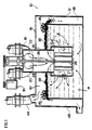
- the reactor 10 constructed in accordance with one embodiment of the invention and useful in chemical and physical processes for removing a component from a gas stream, such as oxidative removal of hydrogen sulfide, comprises an enclosed housing 12 having a standpipe 14 extending from exterior to the upper wall 16 of the housing 12 downwardly into the housing 12.
- Inlet pipes 18,20 communicate with the standpipe 14 through an inlet manifold at its upper end for feeding a hydrogen sulfide-containing gas stream and air to reactor 10.
- the inlet pipes 18,20 have inlet openings 22,24 through which the gas flows.
- the openings are designed to provide a low pressure drop.
- the flow rate of gas streams may range upwardly from a minimum of 50 cu.ft/min. (1.4 m3/min), for example, in excess of 500 cu.ft/min. (14 m3/min), although much higher or lower flow rates may be employed, depending on the intended application of the process.
- the pressure drop across the unit may be quite low and may vary from -5 to +10 in. H2O (- 1.25 - 2.5 kPa), preferably from 0 to less than 5 in. H2O (0-1.25 kPa). For larger units employing a fan or a blower to assist the gas flow rate to the impeller, the pressure drop may be greater.
- a shaft 26 extends through the standpipe 14 and has an impeller 28 mounted at its lower end just below the lower extremity of the standpipe 14.
- a drive motor 30 is mounted to drive the shaft 26.
- the impeller 28 comprises a plurality of radially-extending blades 32.
- the number of such blades may vary and generally at least four blades are employed, with the individual blades being equi-angularly spaced apart.
- the impeller is illustrated with the blades 32 extending vertically. However, other orientations of the blades 32 are possible.
- the standpipe 14 has a diameter dimension related to that of the impeller 28 and the ratio of the diameter of the standpipe 14 to that of the impeller 28 generally may vary from 1:1 to 2:1. However, the ratio may be lower, if the impeller is mounted below the standpipe.
- the impeller 28 generally has a height which corresponds to an approximately 1:1 ratio with its diameter, but the ratio generally may vary from 0.3:1 to 3:1.
- the ratio of the projected cross-sectional area of the shrouded impeller 28 to the cross-sectional area of the cell may vary widely, and often is less but may be more than in a conventional agitated flotation cell, since the reaction is confined to a small volume of the reaction medium and will be determined by the ultimate use to which the apparatus 10 is put.
- the ratio may be as little as 1:2. However, where additional processing of product is required to be effected efficiently, such as flotation of sulfur, the ratio generally will be higher.
- Another function of the impeller 28 is to distribute the induced gases as small bubbles. This result is achieved by rotation of the impeller 28, resulting in shear of liquid and gases to form fine bubbles dimensioned no more than 1 ⁇ 4 inch (6.5 mm).
- a critical parameter in determining an adequate shearing is the velocity of the outer tip of the blades 32.
- a blade tip velocity of at least 350 in/sec (900 cm/sec) is required to achieve efficient (i.e., 99.99%+) removal of hydrogen sulfide, preferably 500 to 700 in/sec (1300-1800 cm/sec). This blade tip velocity is much higher than typically used in a conventional agitated flotation cell, wherein the velocity is about 275 in/sec (700 cm/sec).
- the impeller 28 is surrounded by a cylindrical stationary shroud 34 having a uniform array of circular openings 36 through the wall thereof.
- the shroud 34 generally has a diameter slightly greater than the standpipe 14.
- the shroud 34 is right cylindrical and stationary, it is possible for the shroud 34 to possess other shapes.
- the shroud 34 may be tapered, with the impeller 28 optionally also being tapered.
- the shroud 34 may be rotated, if desired, usually in the opposite direction to the impeller 28.
- openings 36 in the shroud are illustrated as being circular, since this structure is convenient. However, it is possible for the openings to have different geometrical shapes, such as square, rectangular or hexagonal. Further, all the openings 36 need not be of the same shape or size.
- the shroud 34 serves a multiple function in the device.
- the shroud 34 prevents gases from bypassing the impeller 28, assists in the formation of the vortex in the liquid necessary for gas induction, assists in achieving shearing and maintains the turbulence produced by the impeller 28.
- the effect of the impeller-shroud combination may be enhanced by the employment of a series of elongate baffles, provided on the internal wall of the shroud 34, preferably vertically extending from the lower end to the upper end of the openings in the shroud.
- the shroud 34 is spaced only a short distance from the extremity of the impeller blades 30, in order to provide the above-noted functions.
- the ratio of the diameter of the shroud 34 to that of the impeller 28 generally is 2:1 to 1.2:1, preferably approximately 1.5:1.
- the openings 36 In contrast to the shroud in a conventional agitated flotation cell, the openings 36 generally are larger in number and smaller in diameter, in order to provide an increased area for shearing, although an equivalent effect can be achieved using openings of large aspect ratio, such as slits.
- the openings 36 When such circular opening: are employed, the openings 36 generally are uniformly distributed over the wall of the shroud 34 and usually are of equal size.
- the equivalent diameter of the openings 36 often is less than one inch (2.5 cm) and generally should be as small as possible without plugging, preferably 3/8 to 5/8 inch (1-1.6 cm) in diameter, in order to provide for the required gas flow therethrough.
- the area of each such opening 36 generally is, less than the area of a circular opening having an equivalent diameter of one inch (2.5 cm), preferably 3/8 to 5/8 inch (1-1.6 cm).
- the openings have sharp corners to promote shearing.
- the openings 36 are dimensioned to permit a gas flow rate therethrough corresponding to less than 0.02 lb (9 gm) /min/shroud opening, generally down to 0.004 lb (1.8 gm) /min/shroud opening.
- the gas flow rate may be higher at or near the upper limit of capacity of the unit.
- the gas flow rate through the shroud openings is 0.005 to 0.007 lb (2.3-3.2 gm) /min/opening in the shroud.
- the gas velocity index is at least 18 per second per opening in the shroud, preferably at least 24 per second per opening, and more preferably at least 30 per second per opening.
- the gas flow through the openings is typically 0.007 lb (3.2 gm)/min/opening (a gas velocity index of 65 per second per opening) in the shroud, while in a conventional agitated flotation cell of the same unit size the same parameter is 0.03 lb (14 gm)/min/opening (a gas velocity index less than 10 per second per opening) in the shroud.
- the physical dimensions of the openings and the gas flow are significantly different in the gas-liquid contact device of this invention from those in an agitated flotation cell.
- each circular opening is spaced from 0.25 to 0.75 of the diameter of the opening from each other, typically 0.5, although other arrangements are possible.
- the plurality of openings is arranged at a density of less than 2 per square inch (20 per m2) in a regular array.
- the shroud 34 is illustrated as extending downwardly for the height of the impeller 28. It is possible for the shroud 34 to extend below the height of the impeller 28 or for less than its full height, if desired.
- the impeller 28 is located a distance corresponding approximately half the diameter of the impeller 28 from the bottom wall of the reactor 10. It is possible for this dimension to vary from no less than 0.25:1 to 1:1 or greater of the proportion of the diameter dimension of the impeller. This spacing of the impeller 28 from the lower wall allows liquid phase to be drawn into the area between the impeller 28 and the shroud 34 from the mass in the reactor.
- the sulfur particles initially remain suspended in the turbulent reaction medium but grow in the body of the reaction medium to a size which enables them to be floated by the hydrogen sulfide-depleted gas bubbles.
- the sulfur particles have reached a size in the range of 10 to 50 micrometers in diameter, they possess sufficient inertia to penetrate the boundary layer of the gas bubbles to thereby enable them to be floated by the upwardly flowing hydrogen sulfide-depleted gas bubbles.
- odiferous components of the hydrogen sulfide-containing gas stream such as mercaptans, disulfides and odiferous nitrogenous compounds, such as putrescenes and cadaversenes, also may be removed by adsorption on the sulfur particles.
- the floated sulfur At the surface of the aqueous reaction medium, the floated sulfur accumulates as a froth 38 and the hydrogen sulfide-depleted gas bubbles enter an atmosphere 40 of such gas above the reaction medium 42.
- the presence of the froth 38 tends to inhibit entrainment of an aerosol of reaction medium in the atmosphere 40.
- a hydrogen sulfide-depleted gas flow outlet 44 is provided in the upper closure 16 to permit the treated gas stream to pass out of the reactor vessel 12.
- An adequate freeboard above the liquid level in the reaction vessel is provided greater than the thickness of the sulfur-laden froth 38, to further inhibit aerosol entrainment.
- Paddle wheels 46 are provided adjacent the edges of the vessel 12 in operative relation with the sulfur-laden froth 38, so as to skim the sulfur-laden froth from the surface of the reaction medium 42 into collecting launders 48 provided at each side of the vessel 12. The skimmed sulfur is removed periodically or continuously from the launders 48 for further processing.
- the sulfur is obtained in the form of froth containing 15 to 50 wt.% sulfur in reaction medium. Since the sulfur is in the form of particles of a relatively narrow particle size, the sulfur is readily separated from the entrained reaction medium, which is returned to the reactor 10.
- the gas-liquid contact apparatus 10 provides a very compact unit which rapidly and efficiently removes hydrogen sulfide from gas streams containing the same. Such gas streams may have a wide range of concentrations of hydrogen sulfide.
- the compact nature of the unit leads to considerable economies, both in terms of capital cost and operating cost, when compared to conventional hydrogen sulfide-removal systems.
- a pilot plant apparatus was constructed as schematically shown in Figure 1 and was tested for efficiency of removal of hydrogen sulfide from a gas stream containing the same.
- the overall liquid capacity of the tank was 135 L.
- the standpipe had an inside diameter of 71 ⁇ 2 in. (19 cm), and the impeller consisted of six blades and had a diameter of 51 ⁇ 2 in. (14 cm) and a height of 61 ⁇ 4 in (16 cm) and was positioned 21 ⁇ 4 in. (6 cm) from the base of the tank.
- the pilot plant apparatus fitted with a standard froth flotation shroud and impeller combination, was charged with 110 L of an aqueous solution which contained 0.016 mol/L of ethylenediaminetetraacetic acid, iron-ammonium complex and 0.05 mol/L of sodium hydrogen carbonate.
- the pH of the aqueous medium was 8.5.
- the shroud consisted of a stationary cylinder of outside diameter 12 in. (30 cm), height 5 3/4 in (15 cm) and thickness 3/4 in. (2 cm) in which was formed 48 circular openings each 1.25 in. (3 cm) in diameter, for a total circumferential length of 188 inches (477 cm).
- Air containing 4000 ppm by volume of hydrogen sulfide was passed through the apparatus via the standpipe at a rate of 835 L/min. at room temperature while the impeller in the aqueous medium rotated at a rate of 733 rpm., corresponding to a blade tip velocity of about 211 in/sec (535 cm/sec).
- the gas velocity index through the shroud openings was 11.7 per second per opening in the shroud. (The gas flow rate was 0.05 lb (23 gm) /min/opening.) Over the one and a half hour test period, 99.5% of the hydrogen sulfide was removed from the gas stream, leaving a residual amount of H2S in the gas stream of 20 ppm.
- Example 1 The procedure of Example 1 was repeated with an increased impeller rotation rate and higher gas flow rate.
- Air containing 4000 ppm by volume of hydrogen sulfide was passed through the apparatus via the standpipe at a rate of 995 L/min. at room temperature while the impeller in the aqueous medium rotated at a rate of 1772 rpm corresponding to a blade tip velocity of 510 in/sec (13 m/sec).
- the gas velocity index through the shroud openings was 13.7 per second per opening in the shroud. (The gas flow rate was 0.06 lb (27 gm)/min/opening.)
- 99.7% of the hydrogen sulfide was removed from the gas stream, leaving a residual amount of H2S of 11 ppm.
- the pilot plant apparatus was modified and fitted with a shroud and impeller combination as illustrated in Figure 2, was charged with 110 L of an aqueous solution which contained 0.016 mol/L of ethylenediaminetetraacetic acid, iron-ammonium complex and 0.05 mol/L of sodium hydrogen carbonate.
- the pH of the aqueous solution was 8.5.
- the shroud consisted of a stationary cylinder of outside diameter 12 3/4 in. (32 cm), height 81 ⁇ 2 in. (22 cm), and thickness 1 ⁇ 2 in. (1.25 cm) in which was formed 670 openings each of 3/8 in. (1 cm) diameter for a total circumferential length of 789 inches (20.04 m).
- Air containing 4000 ppm by volume of hydrogen sulfide was passed through the apparatus via the standpipe at a rate of 995 L/min. at room temperature while the impeller in the aqueous medium rotated at a rate of 1754 rpm., corresponding to a blade tip velocity of 597 in/sec (15.16 m/sec).
- the gas velocity index through the shroud was 36.3 per second per opening. (The gas flow rate was 0.004 lb (1.8 gm)/min/opening.) Over the two hour test period 99.998% of the hydrogen sulfide was removed from the gas stream, leaving a residual amount of H2S of less than 0.1 ppm.
- Example 1 As may be seen from a comparison of the results presented in Examples 1, 2 and 3, it is possible to remove hydrogen sulfide with greater than 99% efficiency using an agitated flotation cell which is provided with a conventional shroud and impeller construction (Examples 1 and 2), as already described in CA-A- 1,212,819. However, by employing a higher blade tip velocity, as in Example 2, a modest increase in efficiency can be achieved.
- Example 3 With a shroud modified as described therein to provide the critical gas flow rate and using the critical blade tip velocity, efficiency values over 99.99% can be achieved, leaving virtually no residual hydrogen sulfide in the gas stream.
- the pilot plant apparatus of Figure 1 was tested for efficiency of removal of sulfur dioxide from a gas stream containing the same.
- the elements of the pilot plant apparatus were dimensioned as described in Example 3.
- the pilot plant apparatus was charged with 110 L of an aqueous slurry containing 13.2 kg of CaO and 3450 g of MgSO4.7H2O. Air, containing varying amounts of sulfur dioxide was passed through the apparatus via the standpipe at varying flow rates at room temperature, while the impeller in the aqueous slurry rotated at a rate varying from 1760 to 1770 rpm, corresponding to a blade tip velocity of 599 to 602 in/sec (15.21-15.29 m/sec). The corresponding gas velocity indices through the shroud were from 31.1 to 124.5 per second per opening. (The gas flow rates were 0.003 to 0.01 lb (1.4-4.5 gm)/min/opening.)
- Example 4 The procedure of Example 4 was repeated using 110 L of an aqueous slurry of 13.2 kg of calcium carbonate and 3450 g of MgSO4.7H2O.
- the impeller was rotated at a speed of 1770 to 1775 rpm, corresponding to a blade tip velocity of 602 to 604 in/sec (15.29-15.34 m/sec).
- the corresponding gas velocity index through the shroud were 31.1 to 103.8 per second per opening. (The gas flow rates were 0.003 to 0.01 lb (1.4-4.5 gm)/min/opening)
Landscapes
- Chemical & Material Sciences (AREA)
- Engineering & Computer Science (AREA)
- Chemical Kinetics & Catalysis (AREA)
- General Chemical & Material Sciences (AREA)
- Oil, Petroleum & Natural Gas (AREA)
- Analytical Chemistry (AREA)
- Health & Medical Sciences (AREA)
- Environmental & Geological Engineering (AREA)
- Life Sciences & Earth Sciences (AREA)
- Biotechnology (AREA)
- Biomedical Technology (AREA)
- Organic Chemistry (AREA)
- Toxicology (AREA)
- Inorganic Chemistry (AREA)
- General Health & Medical Sciences (AREA)
- Business, Economics & Management (AREA)
- Emergency Management (AREA)
- Physical Or Chemical Processes And Apparatus (AREA)
- Treating Waste Gases (AREA)
- Gas Separation By Absorption (AREA)
Claims (22)
- Verfahren zur Abtrennung eines Bestandteils aus einem Gasstrom, der denselben enthält, in ein flüssiges Medium, umfassend:
Einleiten des Gasstroms in eine abgeschlossene Gas-Flüssigkeit-Kontaktzone, in der sich das flüssige Medium befindet,
ein Flügelrad mit einer Anzahl von Flügelblättern um eine allgemein vertikale Achse mit einer Blattspitzengeschwindigkeit von wenigstens 900 cm/sec (350 Zoll/sec) in dem flüssigen Medium an einer untergetauchten Stelle rotieren lassen, um eine Strömung des Gasstroms längs eines allgemein vertikalen Strömungsweges von außen zur Gas-Flüssigkeits-Kontaktzone zu der untergetauchten Stelle zu bewirken,
wobei das Flügelrad mit einem Mantel umgeben ist, in dem eine Anzahl Öffnungen ausgebildet ist und ausreichend Scherkräfte zwischen den Flügelblättern und der Anzahl Öffnungen erzeugt werden, um den Gasstrom als feine Gasblasen mit einem Durchmesser von nicht mehr als 6,5 mm (1/4 Zoll) zu verteilen und um einen engen Kontakt des Bestandteils und des flüssigen Mediums an der untergetauchten Stelle zu bewirken, um so ein Abtrennen des Bestandteils aus dem Gasstrom in das flüssige Medium zu erzielen,
Zulassen von Strömung von Materialien aus dem Inneren des Mantels durch dessen Öffnungen in den außerhalb des Mantels befindlichen Flüssigkeitskörper mit einem Gasgeschwindigkeitsindex (bei etwa atmosphärischem Druck) von wenigstens 18 je Sekunde je Offnung im Mantel, wobei der Gasgeschwindigkeitsindex das Verhältnis aus der linearen Geschwindigkeit des Gases durch jede Öffnung und dem äquivalenten Durchmesser der Offnung ist, und wobei jegliche Abtrennung des Bestandteils aus dem Gasstrom, der nicht innerhalb des Mantels erfolgt ist, in der außen an den Mantel angrenzenden Zone zu Ende geführt wird, und
Ableiten eines von seinem Bestandteil befreiten Gasstroms aus einer Gasatmosphäre oberhalb des Flüssigkeitsspiegels in der Gas-Flüssigkeits-Kontaktzone nach außen aus der eingeschlossenen Gas-Flüssigkeits-Kontaktzone. - Verfahren nach Anspruch 1, bei dem die Flügelblattgeschwindigkeit 1300 bis 1800 cm/sec (500 bis 700 Zoll/sec) beträgt.
- Verfahren nach Anspruch 1 oder Anspruch 2, bei dem der Gasgeschwindigkeitsindex wenigstens 24 je Sekunde je Öffnung beträgt.
- Verfahren nach einem der Ansprüche 1 bis 3, bei dem der Gasgeschwindigkeitsindex von 30 bis 400 je Sekunde je Öffnung beträgt.
- Verfahren nach einem der Ansprüche 1 bis 4, bei dem jede der Öffnungen kreisrund ist.
- Verfahren nach einem der Ansprüche 1 bis 5, bei dem der genannte Bestandteil ein gasförmiger Bestandteil ist und aus dem Gasstrom durch chemische Umwandlung des gasförmigen Bestandteils abgetrennt wird, um eine unlösliche Phase durch ein chemisches Umsetzungsmittel zu bewirken, das sich in der Gas-Flüssigkeits-Kontaktzone befindet.
- Verfahren nach Anspruch 6, bei dem die unlösliche Phase durch die Gasblasen, wenn diese von Reaktiongasbestandteilen befreit sind, aufschwimmt und es den befreiten Gasblasen ermöglicht wird durch das flüssige Medium aufzusteigen und die unlösliche Phase auf der Oberfläche des flüssigen Mediums in der Gas-Flüssigkeits-Kontaktzone aufschwimmen kann.
- Verfahren nach einem der Ansprüche 1 bis 5, bei dem der Bestandteil aus dem Gasstrom durch physikalische Abtrennung in die flüssige Phase abgetrennt wird.
- Verfahren nach Anspruch 8, bei dem der Bestandteil festes teilchenförmiges Material ist und die physikalische Abtrennung durch Auswaschen des teilchenförmigen Materials aus dem Gasstrom erfolgt, das in dem flüssigen Medium aufzulösen oder zu suspendieren ist.
- Verfahren nach Anspruch 8, bei dem der Bestandteil in Form von Flüssigkeitströpfchen vorliegt und die physikalische Abtrennung durch Auswaschen der Flüssigkeitströpfchen aus dem Gasstrom bewirkt wird, welche in dem flüssigen Medium aufzulösen oder zu suspendieren sind.
- Verfahren nach Anspruch 8, bei dem der Bestandteil als Feuchtigkeit in dem Gasstrom vorliegt und die physikalische Abtrennung durch Absorbieren der Feuchtigkeit aus dem Gasstrom in ein hydrophiles organisches flüssiges Medium bewirkt wird.
- Verfahren nach Anspruch 8, bei dem der Bestandteil thermische Energie ist und die physikalische Abtrennung durch Wärmetausch mit dem flüssigen Medium bewirkt wird.
- Vorrichtung mit der Gas und Flüssigkeit miteinander in Kontakt gebracht werden, umfassend:
eine geschlossene Tankeinrichtung (12),
einen Gaseinlaßverteiler (18, 20) zum Zuführen wenigstens eines Gasstroms durch einen Einlaß in einen oberen Abschluß der Tankeinrichtung (12),
ein Standrohreinrichtung (14), die mit dem Einlaß in Verbindung steht und sich vom oberen Abschluß (16) nach unten in die Tankeinrichtung (12) erstreckt,
eine Flügelradeinrichtung (28) umfassend eine Anzahl von Flügelblättern, die beim unteren Ende des Standrohrs (14) angeordnet und an einer Welle (26) zur Drehung um eine allgemein senkrechte Achse befestigt sind,
eine Antriebseinrichtung (30) zum Drehantrieb der Welle,
ein Mantel (34), der das Flügelrad (28) umschließt und eine Anzahl von Öffnungen (36) hat, die sich durch die Wand des Mantels (34) erstrecken,
wobei jede der Öffnungen (36) im Mantel (34) einen äquivalenten Durchmesser von weniger als 2,5 cm (1 Zoll) derart hat, daß das Verhältnis des äquivalenten Durchmessers zum Durchmesser des Flügelrads kleiner als 0,15 ist und der Gasgeschwindigkeitsindex (bei etwa atomosphärischem Druck) wenigstens 18 je Sekunde je Öffnung beträgt, und der Gasgeschwindigkeitsindex das Verhältnis aus der linearen Geschwindigkeit des Gases und dem äquivalenten Durchmesser der Öffnung ist, und
eine Entlüftungseinrichtung (44) für die Tankeinrichtung (12). - Vorrichtung nach Anspruch 13, bei dem der Mantel (34) einen Durchmesser von 2:1 bis 1,2:1 des Durchmessers des Flügelrads hat.
- Vorrichtung nach Anspruch 13 oder 14, bei dem das Flügelrad (28) eine Höhe hat, die dem 0,3:1 bis 3:1-fachen des Durchmessers des Flügelrads (28) entspricht.
- Vorrichtung nach einem der Ansprüche 13 bis 15, bei dem das Flügelrad (28) wenigstens 4 in gleichem Winkelabstand angeordnete Flügelblätter hat und der Mantel einen Durchmesser aufweist, der etwa dem l,5-fachen dessen des Flügelrads (28) beträgt.
- Vorrichtung nach einem der Ansprüche 13 bis 16, bei dem das Standrohr (14) einen Durchmesser hat, der dem 1:1 bis 2:1-fachen des Durchmessers des Flügelrads (28) beträgt, und der Mantel (34) einen Durchmesser von nicht weniger als dem des Standrohrs aufweist.
- Vorrichtung nach einem der Ansprüche 13 bis 17, bei dem das Flügelrad (28) von der Bodenwandung des Behälters (12) wenigstens nur das 0,25-fache des Durchmessers des Flügelrades (28) beabstandet ist.
- Vorrichtung nach einem der Ansprüche 13 bis 18, bei dem jede Öffnung (36) eine kreisförmige Gestalt hat.
- Vorrichtung nach Anspruch 19, bei der die Öffnungen (36) einen Abstand vom 0,25 bis 0,75-fachen des Durchmessers der Öffnungen voneinander aufweisen.
- Vorrichtung nach Anspruch 19 oder 20, bei der die mehreren Öffnungen mit einer Dichte von weniger als 20 je m² (2 je Quadratzoll) gleichmäßig angeordnet sind.
- Vorrichtung nach einem der Ansprüche 13 bis 21, bei der jede der Öffnungen mit einem äquivalenten Durchmesser von 1 bis 1,6 cm (3/8 bis 5/8 Zoll) dimensioniert ist.
Applications Claiming Priority (7)
| Application Number | Priority Date | Filing Date | Title |
|---|---|---|---|
| CA4652 | 1989-12-05 | ||
| CA 2004652 CA2004652C (en) | 1989-12-05 | 1989-12-05 | Method and apparatus for effecting gas-liquid contact reactions |
| GB909002462A GB9002462D0 (en) | 1990-02-05 | 1990-02-05 | Removal of sulfur dioxide from gaseous streams |
| GB9002462 | 1990-02-05 | ||
| US58242390A | 1990-09-14 | 1990-09-14 | |
| PCT/CA1990/000431 WO1991008038A1 (en) | 1989-12-05 | 1990-12-04 | Method and apparatus for effecting gas-liquid contact |
| US582423 | 1995-12-29 |
Publications (2)
| Publication Number | Publication Date |
|---|---|
| EP0504203A1 EP0504203A1 (de) | 1992-09-23 |
| EP0504203B1 true EP0504203B1 (de) | 1993-11-10 |
Family
ID=27168671
Family Applications (1)
| Application Number | Title | Priority Date | Filing Date |
|---|---|---|---|
| EP91900143A Expired - Lifetime EP0504203B1 (de) | 1989-12-05 | 1990-12-04 | Methode und vorrichtung zur durchführung eines gas-flüssigkeit-kontaktes |
Country Status (13)
| Country | Link |
|---|---|
| EP (1) | EP0504203B1 (de) |
| JP (1) | JPH0677664B2 (de) |
| KR (1) | KR0152244B1 (de) |
| AT (1) | ATE97013T1 (de) |
| AU (1) | AU636495B2 (de) |
| CA (1) | CA2070630C (de) |
| DE (1) | DE69004578T2 (de) |
| DK (1) | DK0504203T3 (de) |
| ES (1) | ES2048007T3 (de) |
| FI (1) | FI922597A0 (de) |
| HU (1) | HU215365B (de) |
| NO (1) | NO178845C (de) |
| WO (1) | WO1991008038A1 (de) |
Families Citing this family (13)
| Publication number | Priority date | Publication date | Assignee | Title |
|---|---|---|---|---|
| US5352421A (en) * | 1989-12-05 | 1994-10-04 | University Of Toronto Innovations Foundation | Method and apparatus for effecting gas-liquid contact |
| US5520818A (en) * | 1989-12-06 | 1996-05-28 | The University Of Toronto Innovations Foundation | Method for effecting gas-liquid contact |
| DE69430127D1 (de) * | 1993-09-01 | 2002-04-18 | Apollo Environmental Syst Corp | Entgasung von flüssigem schwefel |
| US5610199A (en) * | 1994-03-22 | 1997-03-11 | Estee Lauder Inc. | Solid lipophilic composition and process for its preparation |
| US5500130A (en) * | 1994-11-29 | 1996-03-19 | The University Of Toronto Innovations Foundation And Apollo Environmental Systems Corp. | Method for effecting gas-liquid contact |
| DE19539120C1 (de) * | 1995-10-20 | 1997-07-17 | Paul Esser | Verfahren und Vorrichtung zum Einleiten eines Gases in ein Gewässer |
| ES2296500B1 (es) * | 2006-01-24 | 2009-03-16 | Universidad Del Pais Vasco Euskal Herriko Unibertsitatea | Reactor de precipitacion gas-liquido-solido. |
| FR2981580B1 (fr) * | 2011-10-20 | 2013-12-13 | Saipem Sa | Dispositif de collecte et de separation de liquides aqueux et/ou huileux et de liquide cryogenique |
| KR101571250B1 (ko) * | 2014-07-21 | 2015-11-23 | 한국전력공사 | 중탄산나트륨 제조 장치 및 그 제조 방법 |
| KR101589261B1 (ko) * | 2015-03-31 | 2016-01-28 | 정재억 | 습식 스크러빙 장치 |
| RU2756061C2 (ru) * | 2016-09-21 | 2021-09-24 | Онтарио Инк. | Способ и устройство для прямого извлечения ценных минералов в виде агрегатов, состоящих из пузырьков и твердых частиц |
| JP7433751B2 (ja) * | 2018-07-03 | 2024-02-20 | 出光興産株式会社 | ファインバブルの製造装置、及びファインバブルの製造方法 |
| CN111939727A (zh) * | 2020-08-26 | 2020-11-17 | 定远县永发装饰工程有限公司 | 一种工业烟气提纯分解炉 |
Family Cites Families (6)
| Publication number | Priority date | Publication date | Assignee | Title |
|---|---|---|---|---|
| US3911093A (en) * | 1971-10-18 | 1975-10-07 | Stauffer Chemical Co | Recovery of SO{HD 2 {B from waste gas emissions |
| US4009251A (en) * | 1973-08-27 | 1977-02-22 | Rhodia, Inc. | Process for the removal of hydrogen sulfide from gaseous streams by catalytic oxidation of hydrogen sulfide to sulfur while inhibiting the formation of sulfur oxides |
| GB1521785A (en) * | 1976-05-05 | 1978-08-16 | United States Filter Corp | Apparatus for dispersing a gas in a liquid |
| EP0086919B1 (de) * | 1982-01-04 | 1987-09-16 | Mobil Oil Corporation | Verfahren zur selektiven Entfernung von Schwefelwasserstoff aus einem strömenden Gas |
| GB8301968D0 (en) * | 1983-01-25 | 1983-02-23 | Powlesland Eng Ltd | Removal of hydrogen sulphide from gaseous streams |
| DE3712007A1 (de) * | 1987-04-09 | 1988-10-27 | Walter Kroll | Verfahren und vorrichtung zur abtrennung von feststoffen aus einem gasstrom, insbesondere zur reinigung von rauchgas- und abgasstroemen |
-
1990
- 1990-12-04 KR KR1019920701328A patent/KR0152244B1/ko not_active Expired - Fee Related
- 1990-12-04 HU HU9201886A patent/HU215365B/hu not_active IP Right Cessation
- 1990-12-04 AT AT91900143T patent/ATE97013T1/de not_active IP Right Cessation
- 1990-12-04 EP EP91900143A patent/EP0504203B1/de not_active Expired - Lifetime
- 1990-12-04 WO PCT/CA1990/000431 patent/WO1991008038A1/en not_active Ceased
- 1990-12-04 CA CA002070630A patent/CA2070630C/en not_active Expired - Lifetime
- 1990-12-04 ES ES91900143T patent/ES2048007T3/es not_active Expired - Lifetime
- 1990-12-04 DK DK91900143.8T patent/DK0504203T3/da active
- 1990-12-04 DE DE91900143T patent/DE69004578T2/de not_active Expired - Fee Related
- 1990-12-04 JP JP3500610A patent/JPH0677664B2/ja not_active Expired - Lifetime
- 1990-12-04 AU AU78954/91A patent/AU636495B2/en not_active Expired
-
1992
- 1992-06-04 NO NO922210A patent/NO178845C/no unknown
- 1992-06-04 FI FI922597A patent/FI922597A0/fi not_active Application Discontinuation
Non-Patent Citations (1)
| Title |
|---|
| CHEMICAL ABSTRACTS, vol. 81, no. 8, 26 August 1974, Columbus,Ohio,US, p. 242, abstract no. 41073s * |
Also Published As
| Publication number | Publication date |
|---|---|
| KR920703181A (ko) | 1992-12-17 |
| HUT62207A (en) | 1993-04-28 |
| NO922210L (no) | 1992-08-05 |
| KR0152244B1 (ko) | 1998-10-15 |
| FI922597A7 (fi) | 1992-06-04 |
| CA2070630C (en) | 1999-04-06 |
| DE69004578D1 (de) | 1993-12-16 |
| FI922597A0 (fi) | 1992-06-04 |
| NO178845C (no) | 1996-06-19 |
| JPH05500632A (ja) | 1993-02-12 |
| DK0504203T3 (da) | 1994-03-21 |
| HU215365B (hu) | 1998-12-28 |
| HU9201886D0 (en) | 1992-12-28 |
| EP0504203A1 (de) | 1992-09-23 |
| ATE97013T1 (de) | 1993-11-15 |
| WO1991008038A1 (en) | 1991-06-13 |
| DE69004578T2 (de) | 1994-05-05 |
| AU7895491A (en) | 1991-06-26 |
| NO178845B (no) | 1996-03-11 |
| AU636495B2 (en) | 1993-04-29 |
| CA2070630A1 (en) | 1991-06-06 |
| ES2048007T3 (es) | 1994-03-01 |
| JPH0677664B2 (ja) | 1994-10-05 |
| NO922210D0 (no) | 1992-06-04 |
Similar Documents
| Publication | Publication Date | Title |
|---|---|---|
| US5352421A (en) | Method and apparatus for effecting gas-liquid contact | |
| US5527475A (en) | Method for determining the parameters of a gas-liquid contact apparatus | |
| US4229417A (en) | Gas-liquid contacting apparatus | |
| EP0504203B1 (de) | Methode und vorrichtung zur durchführung eines gas-flüssigkeit-kontaktes | |
| US4889701A (en) | Process for oxidizing multivalent metals | |
| EP0243542A1 (de) | Verfahren zur selektiven Entfernung von Schwefelwasserstoff aus einem strömenden Gas | |
| US5174973A (en) | Method and apparatus for effecting gas-liquid contact | |
| US5366698A (en) | Apparatus for effecting gas liquid contact | |
| US3791104A (en) | High energy gas-liquid contacting process | |
| CA1047737A (en) | Recovery of sulfur from sulfur dioxide rich aqueous absorbents | |
| US5500130A (en) | Method for effecting gas-liquid contact | |
| JP3308590B2 (ja) | ガス流から二酸化硫黄を除去する方法およびその装置 | |
| CA2337121A1 (en) | Method and apparatus for effecting gas-liquid contact | |
| IE911768A1 (en) | Method and apparatus for effecting gas-liquid contact | |
| CA2004652C (en) | Method and apparatus for effecting gas-liquid contact reactions | |
| EP0504187B1 (de) | Verfahren und vorrichtung mit zwei laufrädern zur durchführung chemischer umwandlungen | |
| JPH0227868Y2 (de) |
Legal Events
| Date | Code | Title | Description |
|---|---|---|---|
| PUAI | Public reference made under article 153(3) epc to a published international application that has entered the european phase |
Free format text: ORIGINAL CODE: 0009012 |
|
| 17P | Request for examination filed |
Effective date: 19920610 |
|
| AK | Designated contracting states |
Kind code of ref document: A1 Designated state(s): AT BE CH DE DK ES FR GB GR IT LI LU NL SE |
|
| 17Q | First examination report despatched |
Effective date: 19930317 |
|
| GRAA | (expected) grant |
Free format text: ORIGINAL CODE: 0009210 |
|
| AK | Designated contracting states |
Kind code of ref document: B1 Designated state(s): AT BE CH DE DK ES FR GB GR IT LI LU NL SE |
|
| PG25 | Lapsed in a contracting state [announced via postgrant information from national office to epo] |
Ref country code: GR Free format text: LAPSE BECAUSE OF FAILURE TO SUBMIT A TRANSLATION OF THE DESCRIPTION OR TO PAY THE FEE WITHIN THE PRESCRIBED TIME-LIMIT Effective date: 19931110 |
|
| REF | Corresponds to: |
Ref document number: 97013 Country of ref document: AT Date of ref document: 19931115 Kind code of ref document: T |
|
| REF | Corresponds to: |
Ref document number: 69004578 Country of ref document: DE Date of ref document: 19931216 |
|
| EPTA | Lu: last paid annual fee | ||
| ITF | It: translation for a ep patent filed | ||
| REG | Reference to a national code |
Ref country code: ES Ref legal event code: FG2A Ref document number: 2048007 Country of ref document: ES Kind code of ref document: T3 |
|
| ET | Fr: translation filed | ||
| REG | Reference to a national code |
Ref country code: DK Ref legal event code: T3 |
|
| PLBE | No opposition filed within time limit |
Free format text: ORIGINAL CODE: 0009261 |
|
| STAA | Information on the status of an ep patent application or granted ep patent |
Free format text: STATUS: NO OPPOSITION FILED WITHIN TIME LIMIT |
|
| 26N | No opposition filed | ||
| EAL | Se: european patent in force in sweden |
Ref document number: 91900143.8 |
|
| PGFP | Annual fee paid to national office [announced via postgrant information from national office to epo] |
Ref country code: LU Payment date: 19971128 Year of fee payment: 8 |
|
| PGFP | Annual fee paid to national office [announced via postgrant information from national office to epo] |
Ref country code: CH Payment date: 19980128 Year of fee payment: 8 |
|
| PG25 | Lapsed in a contracting state [announced via postgrant information from national office to epo] |
Ref country code: LU Free format text: LAPSE BECAUSE OF NON-PAYMENT OF DUE FEES Effective date: 19981204 |
|
| PG25 | Lapsed in a contracting state [announced via postgrant information from national office to epo] |
Ref country code: LI Free format text: LAPSE BECAUSE OF NON-PAYMENT OF DUE FEES Effective date: 19981231 Ref country code: CH Free format text: LAPSE BECAUSE OF NON-PAYMENT OF DUE FEES Effective date: 19981231 |
|
| REG | Reference to a national code |
Ref country code: CH Ref legal event code: PL |
|
| PGFP | Annual fee paid to national office [announced via postgrant information from national office to epo] |
Ref country code: SE Payment date: 20001204 Year of fee payment: 11 |
|
| PGFP | Annual fee paid to national office [announced via postgrant information from national office to epo] |
Ref country code: DK Payment date: 20001213 Year of fee payment: 11 |
|
| PGFP | Annual fee paid to national office [announced via postgrant information from national office to epo] |
Ref country code: BE Payment date: 20001219 Year of fee payment: 11 |
|
| PGFP | Annual fee paid to national office [announced via postgrant information from national office to epo] |
Ref country code: ES Payment date: 20001220 Year of fee payment: 11 |
|
| PGFP | Annual fee paid to national office [announced via postgrant information from national office to epo] |
Ref country code: AT Payment date: 20001227 Year of fee payment: 11 |
|
| PGFP | Annual fee paid to national office [announced via postgrant information from national office to epo] |
Ref country code: NL Payment date: 20001231 Year of fee payment: 11 |
|
| PG25 | Lapsed in a contracting state [announced via postgrant information from national office to epo] |
Ref country code: DK Free format text: LAPSE BECAUSE OF NON-PAYMENT OF DUE FEES Effective date: 20011204 Ref country code: AT Free format text: LAPSE BECAUSE OF NON-PAYMENT OF DUE FEES Effective date: 20011204 |
|
| PG25 | Lapsed in a contracting state [announced via postgrant information from national office to epo] |
Ref country code: SE Free format text: LAPSE BECAUSE OF NON-PAYMENT OF DUE FEES Effective date: 20011205 |
|
| PG25 | Lapsed in a contracting state [announced via postgrant information from national office to epo] |
Ref country code: BE Free format text: LAPSE BECAUSE OF NON-PAYMENT OF DUE FEES Effective date: 20011231 |
|
| REG | Reference to a national code |
Ref country code: GB Ref legal event code: IF02 |
|
| BERE | Be: lapsed |
Owner name: THE UNIVERSITY OF TORONTO INNOVATIONS FOUNDATION Effective date: 20011231 |
|
| PG25 | Lapsed in a contracting state [announced via postgrant information from national office to epo] |
Ref country code: NL Free format text: LAPSE BECAUSE OF NON-PAYMENT OF DUE FEES Effective date: 20020701 |
|
| EUG | Se: european patent has lapsed |
Ref document number: 91900143.8 |
|
| NLV4 | Nl: lapsed or anulled due to non-payment of the annual fee |
Effective date: 20020701 |
|
| REG | Reference to a national code |
Ref country code: DK Ref legal event code: EBP |
|
| PGFP | Annual fee paid to national office [announced via postgrant information from national office to epo] |
Ref country code: GB Payment date: 20021125 Year of fee payment: 13 |
|
| PGFP | Annual fee paid to national office [announced via postgrant information from national office to epo] |
Ref country code: DE Payment date: 20021126 Year of fee payment: 13 |
|
| PG25 | Lapsed in a contracting state [announced via postgrant information from national office to epo] |
Ref country code: ES Free format text: LAPSE BECAUSE OF NON-PAYMENT OF DUE FEES Effective date: 20021205 |
|
| PGFP | Annual fee paid to national office [announced via postgrant information from national office to epo] |
Ref country code: FR Payment date: 20021211 Year of fee payment: 13 |
|
| PG25 | Lapsed in a contracting state [announced via postgrant information from national office to epo] |
Ref country code: GB Free format text: LAPSE BECAUSE OF NON-PAYMENT OF DUE FEES Effective date: 20031204 |
|
| REG | Reference to a national code |
Ref country code: ES Ref legal event code: FD2A Effective date: 20030113 |
|
| PG25 | Lapsed in a contracting state [announced via postgrant information from national office to epo] |
Ref country code: DE Free format text: LAPSE BECAUSE OF NON-PAYMENT OF DUE FEES Effective date: 20040701 |
|
| GBPC | Gb: european patent ceased through non-payment of renewal fee |
Effective date: 20031204 |
|
| PG25 | Lapsed in a contracting state [announced via postgrant information from national office to epo] |
Ref country code: FR Free format text: LAPSE BECAUSE OF NON-PAYMENT OF DUE FEES Effective date: 20040831 |
|
| REG | Reference to a national code |
Ref country code: FR Ref legal event code: ST |
|
| PG25 | Lapsed in a contracting state [announced via postgrant information from national office to epo] |
Ref country code: IT Free format text: LAPSE BECAUSE OF NON-PAYMENT OF DUE FEES Effective date: 20051204 |