EP0503540B1 - Strangpressvorrichtung zum Herstellen einer Laufflächenlage für Fahrzeugreifen - Google Patents
Strangpressvorrichtung zum Herstellen einer Laufflächenlage für Fahrzeugreifen Download PDFInfo
- Publication number
- EP0503540B1 EP0503540B1 EP92104011A EP92104011A EP0503540B1 EP 0503540 B1 EP0503540 B1 EP 0503540B1 EP 92104011 A EP92104011 A EP 92104011A EP 92104011 A EP92104011 A EP 92104011A EP 0503540 B1 EP0503540 B1 EP 0503540B1
- Authority
- EP
- European Patent Office
- Prior art keywords
- plates
- extrusion head
- base
- fact
- upright
- Prior art date
- Legal status (The legal status is an assumption and is not a legal conclusion. Google has not performed a legal analysis and makes no representation as to the accuracy of the status listed.)
- Expired - Lifetime
Links
- 238000001125 extrusion Methods 0.000 title claims description 23
- 239000013536 elastomeric material Substances 0.000 claims description 5
- 230000003014 reinforcing effect Effects 0.000 claims description 3
- 238000012856 packing Methods 0.000 claims description 2
- 238000004140 cleaning Methods 0.000 description 5
- 238000007789 sealing Methods 0.000 description 2
- 230000002452 interceptive effect Effects 0.000 description 1
- 239000007787 solid Substances 0.000 description 1
Images


Classifications
-
- B—PERFORMING OPERATIONS; TRANSPORTING
- B29—WORKING OF PLASTICS; WORKING OF SUBSTANCES IN A PLASTIC STATE IN GENERAL
- B29C—SHAPING OR JOINING OF PLASTICS; SHAPING OF MATERIAL IN A PLASTIC STATE, NOT OTHERWISE PROVIDED FOR; AFTER-TREATMENT OF THE SHAPED PRODUCTS, e.g. REPAIRING
- B29C48/00—Extrusion moulding, i.e. expressing the moulding material through a die or nozzle which imparts the desired form; Apparatus therefor
- B29C48/25—Component parts, details or accessories; Auxiliary operations
- B29C48/256—Exchangeable extruder parts
- B29C48/2562—Mounting or handling of the die
-
- B—PERFORMING OPERATIONS; TRANSPORTING
- B29—WORKING OF PLASTICS; WORKING OF SUBSTANCES IN A PLASTIC STATE IN GENERAL
- B29C—SHAPING OR JOINING OF PLASTICS; SHAPING OF MATERIAL IN A PLASTIC STATE, NOT OTHERWISE PROVIDED FOR; AFTER-TREATMENT OF THE SHAPED PRODUCTS, e.g. REPAIRING
- B29C48/00—Extrusion moulding, i.e. expressing the moulding material through a die or nozzle which imparts the desired form; Apparatus therefor
- B29C48/15—Extrusion moulding, i.e. expressing the moulding material through a die or nozzle which imparts the desired form; Apparatus therefor incorporating preformed parts or layers, e.g. extrusion moulding around inserts
- B29C48/156—Coating two or more articles simultaneously
-
- B—PERFORMING OPERATIONS; TRANSPORTING
- B29—WORKING OF PLASTICS; WORKING OF SUBSTANCES IN A PLASTIC STATE IN GENERAL
- B29C—SHAPING OR JOINING OF PLASTICS; SHAPING OF MATERIAL IN A PLASTIC STATE, NOT OTHERWISE PROVIDED FOR; AFTER-TREATMENT OF THE SHAPED PRODUCTS, e.g. REPAIRING
- B29C48/00—Extrusion moulding, i.e. expressing the moulding material through a die or nozzle which imparts the desired form; Apparatus therefor
- B29C48/25—Component parts, details or accessories; Auxiliary operations
- B29C48/256—Exchangeable extruder parts
-
- B—PERFORMING OPERATIONS; TRANSPORTING
- B29—WORKING OF PLASTICS; WORKING OF SUBSTANCES IN A PLASTIC STATE IN GENERAL
- B29C—SHAPING OR JOINING OF PLASTICS; SHAPING OF MATERIAL IN A PLASTIC STATE, NOT OTHERWISE PROVIDED FOR; AFTER-TREATMENT OF THE SHAPED PRODUCTS, e.g. REPAIRING
- B29C48/00—Extrusion moulding, i.e. expressing the moulding material through a die or nozzle which imparts the desired form; Apparatus therefor
- B29C48/03—Extrusion moulding, i.e. expressing the moulding material through a die or nozzle which imparts the desired form; Apparatus therefor characterised by the shape of the extruded material at extrusion
- B29C48/09—Articles with cross-sections having partially or fully enclosed cavities, e.g. pipes or channels
-
- B—PERFORMING OPERATIONS; TRANSPORTING
- B29—WORKING OF PLASTICS; WORKING OF SUBSTANCES IN A PLASTIC STATE IN GENERAL
- B29L—INDEXING SCHEME ASSOCIATED WITH SUBCLASS B29C, RELATING TO PARTICULAR ARTICLES
- B29L2030/00—Pneumatic or solid tyres or parts thereof
- B29L2030/002—Treads
Definitions
- the present invention relates to an extrusion device for producing tread plies for road vehicle tires
- the present invention relates to an extrusion device substantially of the type disclosed in EP-A-0 339 510 and comprising an extrusion head, in turn comprising a number of shaped plates, a wire guiding device and a die, and releasable clamping means for packing the plates together.
- said plates When packed together, said plates define an intermediate guide duct for reinforcing wires and two supply ducts for extruded elastomeric material located on opposite sides of the guide duct, and provide for locking together the wire guiding device and the die.
- said clamping means normally comprise a number of rods fitted through said plates and having threaded end portions engaged by lock nuts which, once the plates have been packed together on a press, provide for locking them in the packed position.
- Said rods are usually fitted along the edges of the plates, but cannot be equally spaced to prevent interfering with the supply and guide ducts. This therefore results in uneven clamping pressure and possible distortion of the plates, in turn resulting in poor sealing and leakage of elastomeric material from the lateral surfaces of the extrusion head.
- the aforementioned superimposed plates when in contact with one another, define a package which has two pairs of oppositely bevelled longitudinal edges, and is arranged inside a tubular frame having two internally bevelled concave members each adapted to cooperate with a respective pairs of bevelled lateral edges of the plate package.
- a first of these concave members is mounted in a fixed position on the tubular frame, whereas the second is movable towards the first to provide a taper fit applying a clamping pressure along the longitudinal edges of the plates, but leaving substantially free the central portion of the plates where internal pressure is applied.
- the central portion of the package is instead controlled by a number of screws extending from the tubular frame and completely independent of each other and of the aforementioned concave members.
- the clamping pressure applied by these screws and the concave members may result in an uneven clamping pressure and possible distortion of the plates.
- an extrusion device as defined in claim 1.
- the above extrusion device also comprises a device for releasing the extrusion head; said release device comprising actuating means for selectively moving said plates to and from a mutually contacting position.
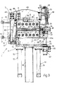
- Device 1 comprises an extrusion head 2; a releasable clamping device 3 for enabling head 2 to be opened when released; and a device 4 for releasing head 2.
- Head 2 is substantially in the form of a rectangular parallelepipedon defined laterally by a front surface 5, a rear surface 6 and two lateral surfaces 7 and 8.
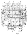
- Head 2 comprises four superimposed plates 9, 10, 11 and 12, of which top plate 9 and adjacent plate 10 are so shaped as to define a duct 13 having a substantially L-shaped horizontal section and the inlet end of which opens on to surface 8 to communicate with the mouth 14 (Fig.s 2 and 3) of an extruder 15 having a connecting plate 16 connected to device 1 by screws 17.
- Bottom plate 12 and adjacent plate 11 are so shaped as to define a duct 18 which, like duct 13, presents a substantially L-shaped horizontal section and an inlet end opening on to surface 8 to communicate with mouth 14 of extruder 15.
- Adjacent plates 10 and 11 are so shaped as to define a straight duct 19, the inlet of which opens on to rear surface 6 for enabling the passage of a number of reinforcing cords (not shown) for a known type of tread ply (not shown), and in which said cords are enclosed between two layers of elastomeric material (not shown).
- head 2 also comprises a wire guiding device 20 located at the outlet of duct 19 and clamped between plates 9 and 12 for guiding said cords to the inlet of a die 21 forming part of head 2.
- Die 21 is located between plates 9 and 12, to the front of wire guiding device 20, for receiving said cords and two layers of elastomeric material from ducts 13 and 18, and feeding them together to a mouth 22 located to the front of front surface 5 of head 2.
- Head 2 also comprises a bottom plate 23 supporting and contacting the bottom surface of plate 12; and a top plate 24 contacting the top surface of and connected integral with plate 9 by screws 25.
- plates 24 and 23 are fitted on their front ends with respective horizontal gibs 26 and 27 defining a front contact surface for die 21 and an opening for the passage of mouth 22.
- each plate 23 and 24 is fitted on the rear end with two substantially L-shaped brackets 29, each having an arm 30 extending vertically towards arm 30 of another bracket 29 to define an opening aligned with the inlet of duct 19.
- Each arm 30 supports an actuator 31 having a pusher 32 elastically engageable with and hydraulically detachable from rear surface 6 of head 2.
- each pusher 32 on brackets 29 connected to plate 23 engages plates 11 and 12, while each pusher 32 on brackets 29 connected to plate 24 engages plates 9 and 10, so as to clamp plates 9 to 12, wire guiding device 20 and die 21 against the vertical shoulder defined by gibs 26 and 27.
- actuators 36 provide for clamping plates 9 to 12, wire guiding device 20 and die 21 against a shoulder surface 38 facing surface 8 and described in more detail later on.
- the function of actuators 36 is to provide for sealing between mouth 14 of extruder 15 and the inlet of ducts 13 and 18.
- Clamping device 3 comprises a plate or base 39 supporting head 2 and connected to the top end of a column 40 having a base 41 supported on adjustable feet 42.
- Clamping device 3 also comprises an upright 43 connected integral with a lateral surface of base 39 and extending upwards from base 39 and outwards of head 2, so as to define, with its lateral surface facing head 2, said shoulder surface 38.
- Upright 43 presents a central opening for the passage of mouth 14 of extruder 15, the screws 17 of which are fitted directly to upright 43, which projects over plate 24 when head 2 is in the closed position, i.e. with all its plates contacting one another.
- Upright 43 presents a top end portion consisting of a multiple fork 44 fitted through with a substantially horizontal pin 45 perpendicular to surface 5, and engaged by end appendixes 46 of respective longitudinal ribs 47 of a crosspiece 48.
- Pin 45 fits through appendixes 46 and defines, together with appendixes 46 and multiple fork 44, a hinge 49 connecting crosspiece 48 to the top of upright 43.
- Crosspiece 48 extends over plate 24 when head 2 is in the closed position, and, on the surface facing plate 24, is fitted integral with a pressure bar 50 parallel to pin 45 and having, at the bottom, a convex surface 51 contacting the top surface of plate 24.
- crosspiece 48 opposite that connected to pin 45 is defined by a solid bar 52 having two through holes 53 perpendicular to the axis of pressure bar 50 and each engaged by the cylindrical body 54 of a hydraulic actuator 55 having a through output rod 56.
- each rod 56 is engaged by a ring nut 57 for axially locking rod 56 in any position within a given range in relation to respective body 54.
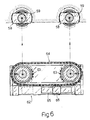
- each rod 56 supports, in rotary manner, a hammer 58 locked axially on rod 56 by means of a cap nut and having a head 59 of substantially rectangular section in a plane perpendicular to rod 56, as shown in Fig.6.
- a portion of each rod 56 extending between head 59 of respective hammer 58 and respective body 54 engages a lateral seat 60 formed in an outer lateral surface of appendix 33 parallel to surface 7 and having a substantially circular section, the diameter of which is less than the length of the longer axis and greater than the length of the shorter axis of head 59 of respective hammer 58.
- heads 59 are set to the locked position with their longer axes parallel to pin 45, and hydraulic actuators 55 are operated for raising rods 56, heads 59 of hammers 58 engage the bottom surface 61 of appendix 33 so as to lower crosspiece 48 and apply the required clamping pressure on head 2 via pressure bar 50.
- Each head 59 therefore defines, with surface 61, a releasable bayonet joint 59a for connecting respective rod 56 and base 39.
- Joints 59a are released, i.e. heads 59 are rotated from said locked position to the release position, wherein hammers 58 are positioned with their shorter axes parallel to pin 45, by means of a rotation device 62 connected to a free end portion of rods 56 and comprising, for each rod 56, a gear 63 fitted to respective hammer 58, a chain 64 looped about the two gears 63, and an actuating device 65 located between the two rods 56 and having an output member 66 connected to one point of chain 64 for moving it one way or the other and rotating hammers 58 about the axes of respective rods 56 and between said locked and release positions.
- a rotation device 62 connected to a free end portion of rods 56 and comprising, for each rod 56, a gear 63 fitted to respective hammer 58, a chain 64 looped about the two gears 63, and an actuating device 65 located between the two rods 56 and having an output member 66 connected to one point of chain 64 for
- clamping device 3 When positioned clamping head 2, clamping device 3 defined by base 39, upright 43, crosspiece 48 and the two actuators 55 therefore presents a ring structure in which are distinguishable a fixed element 67, consisting of base 39 and upright 43, and a mobile element 68 consisting of crosspiece 48 and actuators 55 and movable between the Fig.1 locked position and the Fig.2 release position by virtue of two hydraulic jacks 69, each having a first end connected by a bracket 70 to the bottom end of upright 43, and a second end connected by a bracket 71 to the mid point of crosspiece 48.
- release device 4 comprises six hydraulic jacks 72, each comprising a body 73 connected to the bottom surface of base 39, and an output rod 74 extending upwards from respective body 73 through a respective hole 75 formed through base 39, a hole 76 formed through plate 23, and a hole 77 formed through plate 12.
- Each of rods 74a in a first pair of rods 74 extends upwards through holes 78 formed in plate 11, 10 and 9, and presents a small-diameter threaded end portion engaging a hole 79 formed through plate 24 with which rod 74a is connected integral by means of nut 80.
- Each of rods 74b in a second pair of rods 74 extends upwards through a hole 81 formed in plate 11, and presents a small-diameter threaded end portion engaging a hole 82 formed through plate 10 with which rod 74b is connected integral by means of nut 83.
- Each of rods 74c in a third pair of rods 74 presents a small-diameter threaded end portion engaging a hole 84 formed through plate 11 with which rod 74c is connected integral by means of nut 85.
- hydraulic actuators 55 are operated for raising rods 56 and releasing the pressure on ring nuts 57. Ring nuts 57 are then unscrewed, actuators 55 de-activated, and rotation device 62 operated for rotating hammers 58 into the release position wherein heads 59 are positioned with the longer axis perpendicular to pin 45 (as shown by the dotted line in Fig.6).
- Jacks 69 may now be operated for rotating mobile element 68 about the axis of pin 45 and into the released position shown in Fig.2, wherein crosspiece 48 is positioned substantially along the extension of upright 43 or, at any rate, to the side of head 2.
- hydraulic jacks 72 may be operated for raising rods 74a, 74b and 74c in the required sequence and so raising, firstly, plates 9 and 24 for cleaning duct 18; secondly, plate 10 for cleaning duct 19 and removing, cleaning and servicing wire guiding device 20 and die 21; and, lastly, plate 11 for cleaning duct 19.
- Plates 9, 10 and 11 are raisable by virtue of actuators 31 and 36 being permanently activated for overcoming the thrust exerted by the respective springs and so detaching pushers 32 and 37 from head 2.
- jacks 72 are operated for lowering plates 24, 9, 10 and 11 into contact with one another, after first reassembling wire guiding device 20 and die 21 after lowering plate 11.
- head 2 so formed is adjusted against gibs 27 and shoulder surface 38 by temporarily de-activating actuators 31 and 36.
- Jacks 69 are then operated for setting mobile element 68 to the clamped position, wherein rods 56 engage respective seats 60, and hammers 58 are positioned with heads 59 below surface 61.
- heads 59 are rotated into the clamped position shown by the continuous line in Fig.6, and actuators 55 are operated for exerting the required compacting pressure on head 59 via crosspiece 48 and bar 50.
Landscapes
- Engineering & Computer Science (AREA)
- Mechanical Engineering (AREA)
- Extrusion Moulding Of Plastics Or The Like (AREA)
Claims (7)
- Strangpreßvorrichtung zum Herstellen ebener Laufflächenlagen für Kraftfahrzeugreifen, wobei die Vorrichtung folgendes umfaßt:
einen Extrusionskopf (2), welcher eine Anzahl geformter Platten (9,10,11,12), eine Drahtführungsvorrichtung (20) und eine Düse (21) umfaßt;
und ein wiederlösbares Klemmmittel (3), um die Platten (9,10,11,12) zusammenzupacken; wobei die Platten (9,10,11,12), wenn sie zusammengepackt sind, einen dazwischenliegenden Führungskanal (19) für die Verstärkungsdrähte und zwei Zufuhrkanäle (13,18) für das extrudierte Elastomermaterial ausbilden, die an den gegenüberliegenden Seiten des Führungskanals (20) angeordnet sind, und die Drahtführungsvorrichtung (20) und die Düse (21) miteinander verriegeln, dadurch gekennzeichnet, daß das Klemmmittel (3) eine Ringvorrichtung (3) umfaßt, die außen den Extrusionskopf (2) umgibt, und daß die Ringvorrichtung (3) ein festgelegtes Element (67) umfaßt, das wiederum eine Basis (39) umfaßt, die den Extrusionskopf (2) trägt und in Kontakt dazu angeordnet ist, und daß ein mobiles Segment (68) gegenüberliegend zur Basis (39) ist, und daß Druckmittel mit dem mobilen Segment gekoppelt sind, um dasselbe aus einer Freigabeposition zu einer Verriegelungsposition zu bewegen, in der die Platten (9,10,11,12) zusammengepackt sind und gegen die Basis (39) anliegen. - Vorrichtung nach Anspruch 1, dadurch gekennzeichnet, daß sie ferner eine Vorrichtung (4) zum Lösen des Extrusionskopfes (2) umfaßt, und daß die Lösevorrichtung (4) Betätigungsmittel (72) zum wahlweisen Bewegen der Platten (9,10,11,12) hin und von einer gegenseitigen Kontaktposition weg umfaßt.
- Vorrichtung nach Anspruch 1 oder 2, dadurch gekennzeichnet, daß das festgelegte Element (67) ferner einen Säulenständer (43) umfaßt, der an der Seite des Extrusionskopfes (2) angeordnet und integral mit der Basis (39) ist, und daß das mobile Segment (68) mit dem Säulenständer (43) verbunden ist, um sich in Bezug zu demselben zwischen einer Klemmstellung, in der das mobile Segment (68) mit der Basis (39) verbunden ist und einer Freigabeposition zu drehen, in der das mobile Segment (68) von der Basis (39) gelöst ist.
- Vorrichtung nach Anspruch 3, dadurch gekennzeichnet, daß das mobile Segment (68) ein Kreuzstück (48) umfaßt, das an einem Ende an dem Säulenständer (43) angelenkt und ausgelegt ist, sich in Beziehung zum Säulenständer (43) von einem Ende des Extrusionskopfes und auf ihn zu und zwischen einer Klemmposition, in der das Kreuzstück (48) Verdichtungsdruck auf den Extrusionskopf (2) ausübt und einer Freigabeposition zu bewegen, in der das Kreuzstück (48) an der Seite des Extrusionskopfes (2) positioniert ist.
- Vorrichtung nach Anspruch 4, dadurch gekennzeichnet, daß das mobile Segment (68) ferner Druckmittel (55) umfaßt, die mit dem Ende des Kreuzstückes (48) verbunden sind, gegentiberliegend zu dem, das mit dem Säulenständer (43) verbunden ist, und daß das Druckmittel (55) mit der Basis (39) über ein lösbares Verbindungsmittel (58) verbindbar ist.
- Vorrichtung nach Anspruch 5, dadurch gekennzeichnet, daß das wiederlösbare Verbindungsmittel (58) eine Bajonettverbindung (59a) umfaßt.
- Vorrichtung nach irgendeinem der vorstehenden Ansprüche, dadurch gekennzeichnet, daß sie ferner eine erste und zweite Schulter (27,43) umfaßt, die querverlaufend in Beziehung zu den Platten (9,10,11,12) angeordnet ist und einen Winkel abweichend von 0 bildet, und das Einstellmittel (31,36) zur Quereinstellung der Platten (9,10,11,12) in zwei Richtungen parallel zu den Platten (9,10,11,12) und entsprechend senkrecht zur ersten und zweiten Schulter (27,43) vorgesehen sind.
Applications Claiming Priority (2)
| Application Number | Priority Date | Filing Date | Title |
|---|---|---|---|
| ITTO910192 | 1991-03-15 | ||
| ITTO910192A IT1245461B (it) | 1991-03-15 | 1991-03-15 | Dispositivo di estrusione per la realizzazione di fasce armate per pneumatici di veicoli stradali |
Publications (2)
| Publication Number | Publication Date |
|---|---|
| EP0503540A1 EP0503540A1 (de) | 1992-09-16 |
| EP0503540B1 true EP0503540B1 (de) | 1996-01-31 |
Family
ID=11409090
Family Applications (1)
| Application Number | Title | Priority Date | Filing Date |
|---|---|---|---|
| EP92104011A Expired - Lifetime EP0503540B1 (de) | 1991-03-15 | 1992-03-09 | Strangpressvorrichtung zum Herstellen einer Laufflächenlage für Fahrzeugreifen |
Country Status (7)
| Country | Link |
|---|---|
| US (1) | US5225208A (de) |
| EP (1) | EP0503540B1 (de) |
| JP (1) | JP3237774B2 (de) |
| CA (1) | CA2063014A1 (de) |
| DE (1) | DE69207930T2 (de) |
| ES (1) | ES2083007T3 (de) |
| IT (1) | IT1245461B (de) |
Families Citing this family (6)
| Publication number | Priority date | Publication date | Assignee | Title |
|---|---|---|---|---|
| DE4235280C1 (de) * | 1992-10-20 | 1993-10-14 | Troester Maschf Paul | Spritzkopf für einen Extruder |
| DE4236120C2 (de) * | 1992-10-27 | 1997-07-03 | Troester Maschf Paul | Spritzkopf für eine Extrusionsanlage der Kautschuk oder Kunststoff verarbeitenden Industrie |
| US6682333B2 (en) | 2001-10-25 | 2004-01-27 | Extrusion Dies Industries Llc | Quick-release extrusion die |
| US20060090322A1 (en) * | 2004-10-29 | 2006-05-04 | 3M Innovative Properties Company | Coating die having quick assembly features |
| DE102009022370A1 (de) * | 2009-05-22 | 2010-11-25 | Vmi - Az Extrusion Gmbh | Extrusionsvorrichtung |
| US10322554B2 (en) | 2013-08-29 | 2019-06-18 | The Goodyear Tire & Rubber Company | Tire building drum |
Family Cites Families (19)
| Publication number | Priority date | Publication date | Assignee | Title |
|---|---|---|---|---|
| US2453312A (en) * | 1946-09-07 | 1948-11-09 | Nat Standard Co | Extrusion apparatus |
| US2514211A (en) * | 1947-03-12 | 1950-07-04 | Firestone Tire & Rubber Co | Adjustable extrusion machine |
| US2560022A (en) * | 1947-03-26 | 1951-07-10 | Firestone Tire & Rubber Co | Readily adjustable extrusion device |
| US2607953A (en) * | 1949-03-23 | 1952-08-26 | British Insulated Callenders | Extrusion apparatus |
| US2794213A (en) * | 1954-06-14 | 1957-06-04 | Standard Machinery Company | Extrusion head assembly |
| US3407441A (en) * | 1966-10-14 | 1968-10-29 | Nat Standard Co | Locking mechanism for clamping a die on an extruder |
| US3737262A (en) * | 1971-04-12 | 1973-06-05 | Deering Milliken Res Corp | Extrusion apparatus |
| US3870453A (en) * | 1973-10-15 | 1975-03-11 | Nat Standard Co | Adjustment mechanism for an extruder die |
| DE2937204C2 (de) * | 1979-09-14 | 1982-09-02 | Werner & Pfleiderer, 7000 Stuttgart | Extrudermaschine mit Breitspritzkopf und zugeordnetem Kalander |
| US4316710A (en) * | 1980-03-24 | 1982-02-23 | The Goodyear Tire & Rubber Company | Duplex extruder head |
| US4578024A (en) * | 1985-02-22 | 1986-03-25 | The Firestone Tire & Rubber Company | Coextrusion apparatus |
| DE3506257C1 (de) * | 1985-02-22 | 1986-04-30 | Hermann Berstorff Maschinenbau Gmbh, 3000 Hannover | Aufklappbarer Mehrfach-Strangpresskopf zum Herstellen von Laufstreifenprofilen fuer die Reifenherstellung |
| US4683095A (en) * | 1985-05-08 | 1987-07-28 | The Uniroyal Goodrich Tire Company | Early progressive junction extrusion process and system |
| DE3638623C1 (de) * | 1986-11-12 | 1987-10-22 | Berstorff Gmbh Masch Hermann | Strangpresskopf zum Herstellen von aus verschiedenen Kautschukmischungen bestehenden Laufstreifen fuer Autoreifen |
| DE3736231C3 (de) * | 1986-11-27 | 2000-07-13 | Thyssen Krupp Ag | Extrusionskopf |
| DE3739457C1 (en) * | 1987-11-21 | 1988-09-15 | Berstorff Gmbh Masch Hermann | Procedure and device for the high-pressure sealing of flow channels in a slot die, comprising pivotable upper and lower parts, for rubber and thermoplastics |
| DE3806387A1 (de) * | 1988-02-29 | 1989-09-07 | Troester Maschf Paul | Verfahren und vorrichtung zur bearbeitung von elastomerischen massen, insbesondere kunststoff, kautschuk und deren mischungen |
| IT1219242B (it) * | 1988-04-27 | 1990-05-03 | Firestone Int Dev Spa | Testa di estrusione per materiale in foglio internamente armato con elementi in filo di rinforzo distribuiti con passo relativamente ridotto |
| US4913863A (en) * | 1989-01-30 | 1990-04-03 | Hoechst Celanese Corporation | Split extrusion die assembly for thermoplastic materials and methods of using the same |
-
1991
- 1991-03-15 IT ITTO910192A patent/IT1245461B/it active IP Right Grant
-
1992
- 1992-02-06 US US07/832,184 patent/US5225208A/en not_active Expired - Fee Related
- 1992-03-09 EP EP92104011A patent/EP0503540B1/de not_active Expired - Lifetime
- 1992-03-09 DE DE69207930T patent/DE69207930T2/de not_active Expired - Fee Related
- 1992-03-09 ES ES92104011T patent/ES2083007T3/es not_active Expired - Lifetime
- 1992-03-13 JP JP08838992A patent/JP3237774B2/ja not_active Expired - Fee Related
- 1992-03-13 CA CA002063014A patent/CA2063014A1/en not_active Abandoned
Also Published As
| Publication number | Publication date |
|---|---|
| IT1245461B (it) | 1994-09-20 |
| US5225208A (en) | 1993-07-06 |
| EP0503540A1 (de) | 1992-09-16 |
| ITTO910192A0 (it) | 1991-03-15 |
| DE69207930T2 (de) | 1996-07-04 |
| JPH0596605A (ja) | 1993-04-20 |
| ES2083007T3 (es) | 1996-04-01 |
| ITTO910192A1 (it) | 1992-09-15 |
| CA2063014A1 (en) | 1992-09-16 |
| JP3237774B2 (ja) | 2001-12-10 |
| DE69207930D1 (de) | 1996-03-14 |
Similar Documents
| Publication | Publication Date | Title |
|---|---|---|
| US6613262B1 (en) | Molding system with movable mold modules | |
| EP0503540B1 (de) | Strangpressvorrichtung zum Herstellen einer Laufflächenlage für Fahrzeugreifen | |
| ITVR990033A1 (it) | Macchina monta-smontagomme per ruote di veicoli industriali. | |
| US6463982B1 (en) | Tire inflation apparatus with multiple inflation bells | |
| CH466782A (de) | Verschlossene Verpackung, Verfahren zu deren Herstellung und Einrichtung zur Durchführung des Verfahrens | |
| EP2751016A1 (de) | Hubelement mit ausfahrbarer spülhülse | |
| DE10134808B4 (de) | Schleifvorrichtung für eine Reifenabrichtmaschine | |
| US5056576A (en) | Apparatus for quickly positioning a tube tire on a corresponding wheel rim | |
| DE2028343B2 (de) | Verfahren, laufbelag und vorrichtung zum runderneuern eines fahrzeugluftreifens | |
| EP1342593B1 (de) | Vorrichtung zur Wulst-Positionierung und Füllung von Schlauchlosreifen | |
| CA1241922A (en) | Washing apparatus for filter presses | |
| EP2227369B1 (de) | Extrusionsblasvorrichtung und verfahren zur herstellung von kunststoffbehältern | |
| DE2553637B2 (de) | Verfahren und Bombiertrommel zum Herstellen eines Luftreifens | |
| KR20170088339A (ko) | 다중 압출 프레스 헤드 | |
| ITMO980232A1 (it) | Macchina per smontare e montare pneumatici. | |
| DE1966937C3 (de) | Maschine zum Formschäumen von Schaumstoffteilen | |
| EP1110765B1 (de) | Reifenfüllstation zum Füllen eines Rades mit Druckluft sowie Verfahren hierfür | |
| US6682333B2 (en) | Quick-release extrusion die | |
| DE2311174A1 (de) | Vorrichtung zum ausrichten von insbesondere eisenbahnschienen | |
| EP0712717B1 (de) | Pneumatische Plattenpresse | |
| GB2061808A (en) | Mould-closing arrangement for injection moulding machines | |
| CN116511304A (zh) | 一种管材加工智能扭方机 | |
| DE19640039A1 (de) | Kfz-Rad mit Felge und Notlaufeinrichtung | |
| DE1916868A1 (de) | Blasmaschine fuer Kunststoff-Hohlkoerper | |
| DE4138103C2 (de) | Rohreifen-Einlegevorrichtung bei einer Reifenvulkanisiermaschine |
Legal Events
| Date | Code | Title | Description |
|---|---|---|---|
| PUAI | Public reference made under article 153(3) epc to a published international application that has entered the european phase |
Free format text: ORIGINAL CODE: 0009012 |
|
| AK | Designated contracting states |
Kind code of ref document: A1 Designated state(s): DE ES FR GB IT |
|
| DX | Miscellaneous (deleted) | ||
| 17P | Request for examination filed |
Effective date: 19930311 |
|
| 17Q | First examination report despatched |
Effective date: 19940707 |
|
| GRAA | (expected) grant |
Free format text: ORIGINAL CODE: 0009210 |
|
| AK | Designated contracting states |
Kind code of ref document: B1 Designated state(s): DE ES FR GB IT |
|
| PGFP | Annual fee paid to national office [announced via postgrant information from national office to epo] |
Ref country code: FR Payment date: 19960307 Year of fee payment: 5 |
|
| PGFP | Annual fee paid to national office [announced via postgrant information from national office to epo] |
Ref country code: GB Payment date: 19960311 Year of fee payment: 5 |
|
| REF | Corresponds to: |
Ref document number: 69207930 Country of ref document: DE Date of ref document: 19960314 |
|
| PGFP | Annual fee paid to national office [announced via postgrant information from national office to epo] |
Ref country code: DE Payment date: 19960328 Year of fee payment: 5 |
|
| ET | Fr: translation filed | ||
| PGFP | Annual fee paid to national office [announced via postgrant information from national office to epo] |
Ref country code: ES Payment date: 19960329 Year of fee payment: 5 |
|
| REG | Reference to a national code |
Ref country code: ES Ref legal event code: FG2A Ref document number: 2083007 Country of ref document: ES Kind code of ref document: T3 |
|
| ITF | It: translation for a ep patent filed | ||
| PLBE | No opposition filed within time limit |
Free format text: ORIGINAL CODE: 0009261 |
|
| STAA | Information on the status of an ep patent application or granted ep patent |
Free format text: STATUS: NO OPPOSITION FILED WITHIN TIME LIMIT |
|
| 26N | No opposition filed | ||
| PG25 | Lapsed in a contracting state [announced via postgrant information from national office to epo] |
Ref country code: GB Effective date: 19970309 |
|
| PG25 | Lapsed in a contracting state [announced via postgrant information from national office to epo] |
Ref country code: ES Free format text: LAPSE BECAUSE OF NON-PAYMENT OF DUE FEES Effective date: 19970310 |
|
| GBPC | Gb: european patent ceased through non-payment of renewal fee |
Effective date: 19970309 |
|
| PG25 | Lapsed in a contracting state [announced via postgrant information from national office to epo] |
Ref country code: FR Free format text: LAPSE BECAUSE OF NON-PAYMENT OF DUE FEES Effective date: 19971128 |
|
| PG25 | Lapsed in a contracting state [announced via postgrant information from national office to epo] |
Ref country code: DE Effective date: 19971202 |
|
| REG | Reference to a national code |
Ref country code: FR Ref legal event code: ST |
|
| REG | Reference to a national code |
Ref country code: ES Ref legal event code: FD2A Effective date: 19990301 |
|
| PG25 | Lapsed in a contracting state [announced via postgrant information from national office to epo] |
Ref country code: IT Free format text: LAPSE BECAUSE OF NON-PAYMENT OF DUE FEES Effective date: 20050309 |