EP0503370A1 - Bobine de circuit résonnant pour un oscillateur commandé par un champ magnétique - Google Patents
Bobine de circuit résonnant pour un oscillateur commandé par un champ magnétique Download PDFInfo
- Publication number
- EP0503370A1 EP0503370A1 EP92103243A EP92103243A EP0503370A1 EP 0503370 A1 EP0503370 A1 EP 0503370A1 EP 92103243 A EP92103243 A EP 92103243A EP 92103243 A EP92103243 A EP 92103243A EP 0503370 A1 EP0503370 A1 EP 0503370A1
- Authority
- EP
- European Patent Office
- Prior art keywords
- coil
- band
- circuit
- resonant circuit
- circuit coil
- Prior art date
- Legal status (The legal status is an assumption and is not a legal conclusion. Google has not performed a legal analysis and makes no representation as to the accuracy of the status listed.)
- Granted
Links
- 230000005291 magnetic effect Effects 0.000 title claims description 9
- 238000004804 winding Methods 0.000 claims abstract description 16
- 230000005294 ferromagnetic effect Effects 0.000 claims abstract description 3
- 239000002184 metal Substances 0.000 claims abstract description 3
- 238000004026 adhesive bonding Methods 0.000 claims description 3
- 239000002390 adhesive tape Substances 0.000 claims description 2
- 239000004020 conductor Substances 0.000 abstract description 2
- 238000009434 installation Methods 0.000 abstract 1
- 239000000243 solution Substances 0.000 description 4
- 239000003990 capacitor Substances 0.000 description 3
- 238000004519 manufacturing process Methods 0.000 description 3
- 230000035945 sensitivity Effects 0.000 description 3
- 230000015572 biosynthetic process Effects 0.000 description 1
- 238000011161 development Methods 0.000 description 1
- 230000018109 developmental process Effects 0.000 description 1
- 238000010586 diagram Methods 0.000 description 1
- 230000000694 effects Effects 0.000 description 1
- 238000005516 engineering process Methods 0.000 description 1
- 239000003302 ferromagnetic material Substances 0.000 description 1
- 238000001746 injection moulding Methods 0.000 description 1
- 238000009413 insulation Methods 0.000 description 1
- 238000005259 measurement Methods 0.000 description 1
- 238000012544 monitoring process Methods 0.000 description 1
- 230000035699 permeability Effects 0.000 description 1
- 238000012545 processing Methods 0.000 description 1
Images

Classifications
-
- H—ELECTRICITY
- H01—ELECTRIC ELEMENTS
- H01F—MAGNETS; INDUCTANCES; TRANSFORMERS; SELECTION OF MATERIALS FOR THEIR MAGNETIC PROPERTIES
- H01F17/00—Fixed inductances of the signal type
- H01F17/04—Fixed inductances of the signal type with magnetic core
- H01F17/045—Fixed inductances of the signal type with magnetic core with core of cylindric geometry and coil wound along its longitudinal axis, i.e. rod or drum core
-
- H—ELECTRICITY
- H01—ELECTRIC ELEMENTS
- H01F—MAGNETS; INDUCTANCES; TRANSFORMERS; SELECTION OF MATERIALS FOR THEIR MAGNETIC PROPERTIES
- H01F5/00—Coils
Definitions
- the invention relates to a resonant circuit coil for a magnetic field-controlled oscillator with a coil body, a winding and a coil core made of amorphous, ferromagnetic metal.
- oscillators of this type in which the oscillating circuit coils represent magnetic sensors with extremely high sensitivity and mechanical and thermal robustness.
- the oscillators that can be controlled by the magnetic fields of the flowing currents for monitoring current flows in electrical lines, for example vehicle lamps or other, preferably safety-relevant systems and systems.
- electrical lines for example vehicle lamps or other, preferably safety-relevant systems and systems.
- Other applications are speed and angle measurements, whereby very slow movements can also be detected, as well as path and position determinations.
- the measured value is formed by changing the magnetic properties of a magnetic circuit consisting of a permanent magnet and a resonant circuit coil or of its coil core, in the end by changing the permeability of the coil core by either a relative movement of two magnetic circuit elements or a field distortion caused by movement relative to the sensor, ferromagnetic material.
- the resonant circuit coil acting as a sensor and at the same time being an element of the signal-processing oscillator circuit be suitable for large-volume production, ie the resonant circuit coil must be designed so that it consists of simple and easy to assemble components constructed insensitive to tolerances and even on a suitable carrier, for example a printed circuit board, can be assembled without any problems, so that the requirements for mechanical assembly are met even with a relatively small size.
- the object on which the invention is based is therefore to create a resonant circuit coil of the type mentioned at the outset, which can be satisfactorily reproduced when it is manufactured under large-series conditions with as little manufacturing and assembly effort as possible.
- the solution to the problem provides that a winding mandrel is formed between cheeks integrally formed on the coil body of the oscillating circuit coil, that the coil core is designed in the form of a band, and that the band is fastened to a surface which has just been formed on the winding mandrel.
- the coil core is designed in the form of a tape and that the tape can be attached to the coil body from the outside, for example by direct gluing or by using a carrier coated on both sides.
- the coil body is designed in such a way that the band-shaped coil core extends over the entire length of the bobbin can be attached.
- the solution found can thus be produced without any problems.
- it can be used universally and in particular also in cost-critical applications, for example in vehicle technology.
- the circuit according to FIG. 1 represents an emitter-coupled oscillator with an oscillating circuit connected in parallel with a filter capacitor 2, which is used for short-circuiting interference voltages, consisting of an emitter resistor 5 assigned to two transistors 3 and 4 connected in parallel, as well as a capacitor 6 and a parallel connected Voice circuit coil 7, which the frequency-determining variables, d. H. specify the capacitance and the inductance of the oscillating circuit.
- a capacitor 8 is used to decouple the signal of the oscillating circuit.
- the output stage 9 connected downstream of the oscillator 1 consists of a voltage divider formed by resistors 10 and 11, which is used to set the operating point of a transistor 12. With 13 the load resistance of the transistor 12 is designated. After the input voltage has been applied, a signal according to the voltage-time diagram shown is present at output 14 of output stage 9.
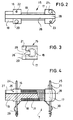
- the coil former 15 produced by the injection molding process has two cheeks 16 and 17, between which a winding mandrel 18 which is cylindrical in the present exemplary embodiment and which can also have an elongated, in any case a rounded cross-sectional shape, is formed.
- a lug 19 attached to the coil former 15 serves to receive the coil former in a winding device, while the pins 20 and 21, which are offset on the cheeks 16 and 17, are provided for fixing the resonant circuit coil 7 on a suitable carrier, not shown, preferably a printed circuit board are.
- Openings 22 and 23 formed in the cheeks 16 and 17 serve to press in contact pins 24 and 25 (FIG. 4).
- the band-shaped coil core 27 is preferably attached to the coil body 15 by gluing on the base surface 28 of the groove 26. It is also conceivable to use a double-sided coated adhesive tape as a carrier and fastening element for the band-shaped coil core 27.
- the winding mandrel 18 can also be provided with a flat surface. It is crucial for the resonant circuit coil 7 according to the invention that the attachment or fastening surface for the band-shaped coil core 27 continues over the entire length of the coil body 15 in order to achieve the greatest possible sensitivity.
- the contact pins 24 and 25 serve, on the one hand, together with the fixing pins 20 and 21 to fasten the voice circuit coil 7 to a printed circuit board by reaching through the printed circuit board and being connected to conductor tracks, and on the other hand to attach and contact the cable ends 29 and 30 on the winding mandrel 18 applied winding 31 of the voice circuit coil 7.
Landscapes
- Engineering & Computer Science (AREA)
- Power Engineering (AREA)
- Microelectronics & Electronic Packaging (AREA)
- Coils Or Transformers For Communication (AREA)
- Inductance-Capacitance Distribution Constants And Capacitance-Resistance Oscillators (AREA)
Applications Claiming Priority (2)
| Application Number | Priority Date | Filing Date | Title |
|---|---|---|---|
| DE9102779U DE9102779U1 (de) | 1991-03-08 | 1991-03-08 | Schwingkreisspule für einen magnetfeldgesteuerten Oszillator |
| DE9102779U | 1991-03-08 |
Publications (2)
| Publication Number | Publication Date |
|---|---|
| EP0503370A1 true EP0503370A1 (fr) | 1992-09-16 |
| EP0503370B1 EP0503370B1 (fr) | 1995-10-25 |
Family
ID=6865041
Family Applications (1)
| Application Number | Title | Priority Date | Filing Date |
|---|---|---|---|
| EP92103243A Expired - Lifetime EP0503370B1 (fr) | 1991-03-08 | 1992-02-26 | Bobine de circuit résonnant pour un oscillateur commandé par un champ magnétique |
Country Status (4)
| Country | Link |
|---|---|
| EP (1) | EP0503370B1 (fr) |
| JP (1) | JPH0739205Y2 (fr) |
| DE (2) | DE9102779U1 (fr) |
| ES (1) | ES2085507T3 (fr) |
Cited By (3)
| Publication number | Priority date | Publication date | Assignee | Title |
|---|---|---|---|---|
| DE19538757C1 (de) * | 1995-10-18 | 1997-03-06 | Vdo Schindling | Magnetfeldsensor |
| DE10249919A1 (de) * | 2002-10-26 | 2004-05-13 | Festo Ag & Co. | Spulenanordnung als Magnetfeldsensor |
| DE19547091B4 (de) * | 1995-12-16 | 2005-04-07 | Kaschke Kg (Gmbh & Co.) | Antennenspule mit oberflächenmontierbarem Gehäuse und Verfahren zu deren Herstellung |
Families Citing this family (2)
| Publication number | Priority date | Publication date | Assignee | Title |
|---|---|---|---|---|
| US6466121B1 (en) * | 2000-01-14 | 2002-10-15 | Delphi Technologies, Inc. | Coil assembly |
| JP6968720B2 (ja) * | 2018-01-31 | 2021-11-17 | ヒロセ電機株式会社 | ワイヤ巻回方法および磁気センサ |
Citations (3)
| Publication number | Priority date | Publication date | Assignee | Title |
|---|---|---|---|---|
| DE3334827A1 (de) * | 1983-09-27 | 1985-04-11 | Vogt Gmbh & Co Kg, 8391 Erlau | Stoerschutzdrossel und verfahren zur herstellung solcher stoerschutzdrosseln |
| GB2157087A (en) * | 1984-03-13 | 1985-10-16 | Weyrad | Improvements relating to linearity coils |
| EP0351583A1 (fr) * | 1988-07-20 | 1990-01-24 | VOGT electronic Aktiengesellschaft | Duo-bobine |
Family Cites Families (2)
| Publication number | Priority date | Publication date | Assignee | Title |
|---|---|---|---|---|
| JPS5712283B2 (fr) * | 1973-12-18 | 1982-03-10 | ||
| JPS60233904A (ja) * | 1984-05-04 | 1985-11-20 | Matsushita Electric Ind Co Ltd | アンテナ装置 |
-
1991
- 1991-03-08 DE DE9102779U patent/DE9102779U1/de not_active Expired - Lifetime
-
1992
- 1992-02-26 EP EP92103243A patent/EP0503370B1/fr not_active Expired - Lifetime
- 1992-02-26 DE DE59204087T patent/DE59204087D1/de not_active Expired - Lifetime
- 1992-02-26 ES ES92103243T patent/ES2085507T3/es not_active Expired - Lifetime
- 1992-03-06 JP JP1992011401U patent/JPH0739205Y2/ja not_active Expired - Lifetime
Patent Citations (3)
| Publication number | Priority date | Publication date | Assignee | Title |
|---|---|---|---|---|
| DE3334827A1 (de) * | 1983-09-27 | 1985-04-11 | Vogt Gmbh & Co Kg, 8391 Erlau | Stoerschutzdrossel und verfahren zur herstellung solcher stoerschutzdrosseln |
| GB2157087A (en) * | 1984-03-13 | 1985-10-16 | Weyrad | Improvements relating to linearity coils |
| EP0351583A1 (fr) * | 1988-07-20 | 1990-01-24 | VOGT electronic Aktiengesellschaft | Duo-bobine |
Cited By (4)
| Publication number | Priority date | Publication date | Assignee | Title |
|---|---|---|---|---|
| DE19538757C1 (de) * | 1995-10-18 | 1997-03-06 | Vdo Schindling | Magnetfeldsensor |
| US6150811A (en) * | 1995-10-18 | 2000-11-21 | Mannesmann Vdo Ag | Magnetic field sensor for stable magnetic field measurement over a wide temperature range |
| DE19547091B4 (de) * | 1995-12-16 | 2005-04-07 | Kaschke Kg (Gmbh & Co.) | Antennenspule mit oberflächenmontierbarem Gehäuse und Verfahren zu deren Herstellung |
| DE10249919A1 (de) * | 2002-10-26 | 2004-05-13 | Festo Ag & Co. | Spulenanordnung als Magnetfeldsensor |
Also Published As
| Publication number | Publication date |
|---|---|
| JPH0739205Y2 (ja) | 1995-09-06 |
| EP0503370B1 (fr) | 1995-10-25 |
| DE59204087D1 (de) | 1995-11-30 |
| DE9102779U1 (de) | 1991-05-29 |
| ES2085507T3 (es) | 1996-06-01 |
| JPH04127614U (ja) | 1992-11-20 |
Similar Documents
| Publication | Publication Date | Title |
|---|---|---|
| DE69502512T2 (de) | Magnetischer Lagesensor mit Hallsonde | |
| DE19680088B4 (de) | Kalibrier- und Herstellungsverfahren für einen Magnetsensor | |
| EP1792321B1 (fr) | Composant support, dispositif bobine de choc antiparasites et leur procede de production | |
| DE3827937A1 (de) | Elektrischer messwertaufnehmer | |
| DE20018538U1 (de) | Sensormodul | |
| DE69204179T2 (de) | Gehäuse mit elektronischer Schaltung und daran befestigtem Positionssensor. | |
| DE3523593A1 (de) | Beschleunigungsmessgeraet | |
| DE3133035C2 (de) | Vibrationsmeßfühler | |
| DE4015311C2 (de) | Elektrische Schaltungsanordnung | |
| DE4219923C2 (de) | Magnet-Sensor | |
| EP0503370B1 (fr) | Bobine de circuit résonnant pour un oscillateur commandé par un champ magnétique | |
| DE10157796A1 (de) | Dreidimensionale Wicklungsanordnung | |
| DE102007002085B3 (de) | Messanordnung | |
| DE3014416C2 (de) | Annäherungsschalter | |
| DE2931381C2 (de) | Auslenkungs- oder Hubfühler | |
| DE102017126887B4 (de) | Näherungssensor | |
| DE3133061C2 (de) | Drehwinkelmeßfühler | |
| DE10051138A1 (de) | Anordnung zur potentialfreien Messung hoher Ströme | |
| DE19729312A1 (de) | Absolutes magnetisches Längenmeßsystem | |
| EP0540955B1 (fr) | Dispositif pour fixer un aimant permanent en forme de barre | |
| DE102011010682B3 (de) | Spulenanordnung und Sensor | |
| EP0545058B1 (fr) | Capteur de changement de cap pour véhicules | |
| EP0393599B1 (fr) | Bobine électrique montable en surface | |
| EP0962946B1 (fr) | Bobine de montage verticale pour cartes à circuit imprimé | |
| DE102022105605B3 (de) | Sensoreinheit |
Legal Events
| Date | Code | Title | Description |
|---|---|---|---|
| PUAI | Public reference made under article 153(3) epc to a published international application that has entered the european phase |
Free format text: ORIGINAL CODE: 0009012 |
|
| AK | Designated contracting states |
Kind code of ref document: A1 Designated state(s): CH DE ES FR GB LI |
|
| 17P | Request for examination filed |
Effective date: 19930304 |
|
| 17Q | First examination report despatched |
Effective date: 19950209 |
|
| GRAA | (expected) grant |
Free format text: ORIGINAL CODE: 0009210 |
|
| AK | Designated contracting states |
Kind code of ref document: B1 Designated state(s): CH DE ES FR GB LI |
|
| REF | Corresponds to: |
Ref document number: 59204087 Country of ref document: DE Date of ref document: 19951130 |
|
| GBT | Gb: translation of ep patent filed (gb section 77(6)(a)/1977) |
Effective date: 19960112 |
|
| PGFP | Annual fee paid to national office [announced via postgrant information from national office to epo] |
Ref country code: CH Payment date: 19960220 Year of fee payment: 5 |
|
| ET | Fr: translation filed | ||
| RAP2 | Party data changed (patent owner data changed or rights of a patent transferred) |
Owner name: VDO ADOLF SCHINDLING AG |
|
| REG | Reference to a national code |
Ref country code: ES Ref legal event code: FG2A Ref document number: 2085507 Country of ref document: ES Kind code of ref document: T3 |
|
| PLBE | No opposition filed within time limit |
Free format text: ORIGINAL CODE: 0009261 |
|
| STAA | Information on the status of an ep patent application or granted ep patent |
Free format text: STATUS: NO OPPOSITION FILED WITHIN TIME LIMIT |
|
| 26N | No opposition filed | ||
| PG25 | Lapsed in a contracting state [announced via postgrant information from national office to epo] |
Ref country code: CH Effective date: 19970228 Ref country code: LI Effective date: 19970228 |
|
| REG | Reference to a national code |
Ref country code: CH Ref legal event code: PL |
|
| PGFP | Annual fee paid to national office [announced via postgrant information from national office to epo] |
Ref country code: ES Payment date: 20000217 Year of fee payment: 9 |
|
| PG25 | Lapsed in a contracting state [announced via postgrant information from national office to epo] |
Ref country code: ES Free format text: LAPSE BECAUSE OF NON-PAYMENT OF DUE FEES Effective date: 20010227 |
|
| REG | Reference to a national code |
Ref country code: GB Ref legal event code: IF02 |
|
| REG | Reference to a national code |
Ref country code: ES Ref legal event code: FD2A Effective date: 20021016 |
|
| REG | Reference to a national code |
Ref country code: FR Ref legal event code: ST Effective date: 20061031 |
|
| REG | Reference to a national code |
Ref country code: FR Ref legal event code: D3 |
|
| PGFP | Annual fee paid to national office [announced via postgrant information from national office to epo] |
Ref country code: FR Payment date: 20110302 Year of fee payment: 20 Ref country code: DE Payment date: 20110228 Year of fee payment: 20 |
|
| PGFP | Annual fee paid to national office [announced via postgrant information from national office to epo] |
Ref country code: GB Payment date: 20110217 Year of fee payment: 20 |
|
| REG | Reference to a national code |
Ref country code: DE Ref legal event code: R071 Ref document number: 59204087 Country of ref document: DE |
|
| REG | Reference to a national code |
Ref country code: DE Ref legal event code: R071 Ref document number: 59204087 Country of ref document: DE |
|
| REG | Reference to a national code |
Ref country code: GB Ref legal event code: PE20 Expiry date: 20120225 |
|
| PG25 | Lapsed in a contracting state [announced via postgrant information from national office to epo] |
Ref country code: DE Free format text: LAPSE BECAUSE OF EXPIRATION OF PROTECTION Effective date: 20120227 |
|
| PG25 | Lapsed in a contracting state [announced via postgrant information from national office to epo] |
Ref country code: GB Free format text: LAPSE BECAUSE OF EXPIRATION OF PROTECTION Effective date: 20120225 |