EP0502549A2 - Dispositif de surveillance de l'étincelle dans une installation d'allumage - Google Patents
Dispositif de surveillance de l'étincelle dans une installation d'allumage Download PDFInfo
- Publication number
- EP0502549A2 EP0502549A2 EP92103903A EP92103903A EP0502549A2 EP 0502549 A2 EP0502549 A2 EP 0502549A2 EP 92103903 A EP92103903 A EP 92103903A EP 92103903 A EP92103903 A EP 92103903A EP 0502549 A2 EP0502549 A2 EP 0502549A2
- Authority
- EP
- European Patent Office
- Prior art keywords
- voltage
- ignition
- storage inductor
- circuit
- spark
- Prior art date
- Legal status (The legal status is an assumption and is not a legal conclusion. Google has not performed a legal analysis and makes no representation as to the accuracy of the status listed.)
- Granted
Links
- 238000000034 method Methods 0.000 claims abstract description 10
- 238000012544 monitoring process Methods 0.000 claims abstract description 10
- 239000003990 capacitor Substances 0.000 claims description 8
- 238000011156 evaluation Methods 0.000 claims description 5
- 238000010586 diagram Methods 0.000 description 3
- 239000003054 catalyst Substances 0.000 description 2
- 230000010354 integration Effects 0.000 description 2
- 238000004804 winding Methods 0.000 description 2
- 238000002485 combustion reaction Methods 0.000 description 1
- 238000010276 construction Methods 0.000 description 1
- 230000006378 damage Effects 0.000 description 1
- 238000013461 design Methods 0.000 description 1
- 238000001514 detection method Methods 0.000 description 1
- 238000011161 development Methods 0.000 description 1
- 230000018109 developmental process Effects 0.000 description 1
- 230000003628 erosive effect Effects 0.000 description 1
- 239000000446 fuel Substances 0.000 description 1
- 238000002347 injection Methods 0.000 description 1
- 239000007924 injection Substances 0.000 description 1
- 238000005259 measurement Methods 0.000 description 1
- 230000000737 periodic effect Effects 0.000 description 1
- 238000012360 testing method Methods 0.000 description 1
- 238000011144 upstream manufacturing Methods 0.000 description 1
Images

Classifications
-
- F—MECHANICAL ENGINEERING; LIGHTING; HEATING; WEAPONS; BLASTING
- F02—COMBUSTION ENGINES; HOT-GAS OR COMBUSTION-PRODUCT ENGINE PLANTS
- F02P—IGNITION, OTHER THAN COMPRESSION IGNITION, FOR INTERNAL-COMBUSTION ENGINES; TESTING OF IGNITION TIMING IN COMPRESSION-IGNITION ENGINES
- F02P3/00—Other installations
- F02P3/02—Other installations having inductive energy storage, e.g. arrangements of induction coils
- F02P3/04—Layout of circuits
- F02P3/0407—Opening or closing the primary coil circuit with electronic switching means
- F02P3/0435—Opening or closing the primary coil circuit with electronic switching means with semiconductor devices
-
- F—MECHANICAL ENGINEERING; LIGHTING; HEATING; WEAPONS; BLASTING
- F02—COMBUSTION ENGINES; HOT-GAS OR COMBUSTION-PRODUCT ENGINE PLANTS
- F02P—IGNITION, OTHER THAN COMPRESSION IGNITION, FOR INTERNAL-COMBUSTION ENGINES; TESTING OF IGNITION TIMING IN COMPRESSION-IGNITION ENGINES
- F02P11/00—Safety means for electric spark ignition, not otherwise provided for
- F02P11/06—Indicating unsafe conditions
-
- F—MECHANICAL ENGINEERING; LIGHTING; HEATING; WEAPONS; BLASTING
- F02—COMBUSTION ENGINES; HOT-GAS OR COMBUSTION-PRODUCT ENGINE PLANTS
- F02P—IGNITION, OTHER THAN COMPRESSION IGNITION, FOR INTERNAL-COMBUSTION ENGINES; TESTING OF IGNITION TIMING IN COMPRESSION-IGNITION ENGINES
- F02P17/00—Testing of ignition installations, e.g. in combination with adjusting; Testing of ignition timing in compression-ignition engines
- F02P17/12—Testing characteristics of the spark, ignition voltage or current
Definitions
- the invention relates to a method for ignition monitoring of an ignition system with a storage choke, on which the electrical energy required to generate an ignition spark is stored, and an ignition coil, to which this energy is transmitted for generating the ignition spark, and a device for ignition monitoring of an ignition system with a Storage choke, on which the supply voltage is connected, and an ignition coil connected in parallel.
- an ignition system for an internal combustion engine it is desirable to detect a misfire, that is to say the absence of an ignition spark, in order, for example, to prevent the fuel supplied to the engine from not being burned, which can lead to destruction of the catalyst, in particular in the case of an exhaust system with a catalyst .
- the object underlying the invention is therefore to develop a method and an apparatus, i.e. to create a circuit arrangement of the type mentioned at the beginning with which a clear detection is possible as to whether an ignition spark is present between the electrodes of the spark plugs supplied by the ignition system or whether a short circuit or shunt has occurred or the ignition coil is not under load on the high voltage side, which is e.g. the case is when the ignition cable has fallen off.
- This object is achieved in the method according to the invention in that the voltage difference between the voltage rise at the storage inductor and the supply voltage and the voltage difference across the storage inductor are detected and the absence of at least one of these voltage difference signals is evaluated as an indication of a fault in the ignition system.
- the circuit arrangement according to the invention stands out by three voltage handles for the supply voltage and for the two voltages on the storage inductor, which supply corresponding voltage signals, and an evaluation circuit which, in the absence of at least one of these voltage signals, generates an error signal.
- the design according to the invention also offers the possibility of measuring the spark life, the circuit arrangement according to the invention being able to be produced at low cost and requiring little space.
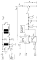
- the ignition system shown in Fig. 1 consists of a storage inductor L0, to which the supply voltage + UB is located and in which energy is stored via a transistor T0, which is switched through by a control when a switch S0 is closed, between the storage inductor L0 and an ignition coil ZSP0 connected in parallel to it, the ignition coil ZSP0 is transmitted.
- the secondary winding of the ignition coil ZSP0 is connected in the usual way to the spark gap of a spark plug.
- voltage signals are tapped at the storage choke L0. These voltage signals are the voltages U20 and U21 on both sides of the storage inductor L0, and additionally the supply voltage UB, which are shown in FIGS. 3b and 4c.
- the voltages U20 and U21 are the voltage increase at the connection of the storage inductor L0, at which the supply voltage + UB is located, and the voltage increase at the collector of the switching transistor T0.
- a diode D0 which only allows a current in the direction of the storage inductor L0, and two capacitors C0, C1 are connected, the other connection of which is connected to ground.
- the voltage taps for the voltage + U21, + U20 and the supply voltage + UB are direct or via resistors R1, R2 (+ U21, + UB) and a Zener diode ZD1 (+ UB ) connected to a circuit, preferably in the form of two optocouplers Opt0 and Opt1, connected in series, with a logic AND function, which logically combines the voltage differences U20-UB and U21-U20.
- a transistor T1 which serves as a switch, is at its base due to the voltage drop controlled at the resistor R3 and is connected with its collector-emitter path, for example via a resistor R6, between the output of the optocoupler Opt0 and ground.
- a resistor R5, which is connected upstream of the base of the transistor T1, serves to limit the current.
- a voltage UA which is representative of the state of the spark gap of the ignition system, is tapped at the collector of transistor T1 via resistor R6. If this voltage UA has a high potential, then there is an error.
- the circuit arrangement according to the invention with the structure shown in detail in FIG. 2 operates in the following way:
- the diode D0 is provided which, when the storage inductor L0 is discharged, prevents this voltage surge + U20 from being short-circuited via the network.
- the capacitors C0 and C1 integrate the pulse occurring when the storage choke L0 is discharged.
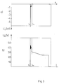
- the voltage rise + U20 at capacitor C1 provides a direct statement about the load on the ignition coil ZSP0 (shunt of the ignition electrodes).
- the voltage rise + U21 at the collector of transistor T0 is also used for the evaluation.
- the corresponding voltage difference U21-U20 is present over a period of time that corresponds to the spark life at the electrodes.
- the two voltage difference signals U21-U20 and U20-UB are linked via the outputs of the optocoupling Opt0, Opt1 according to the logical AND function.
- the two optocouplers Opt0, Opt1 therefore form an AND gate.
- Resistor R3 no voltage drop. As a result, the voltage UA tapped at the transistor T1 is at a high value. Since the voltage across resistor R3 is only present for as long as a spark is present between the ignition electrodes, this signal can be used to measure the burning duration, which also makes it possible to make a statement about the condition of the electrodes.
- the integration element consisting of capacitor C2 and resistor R4 is provided. As long as periodic ignition takes place, the transistor T1 conducts, so that the output voltage UA is at a low value.
- This output voltage UA of the transistor T1 can therefore provide a direct and unambiguous statement about the load on the ignition coil and whether the ignition coil is short-circuited or not.
- the circuit arrangement according to the invention makes this possible with a simple, inexpensive construction of simple components with a simple connection (no high voltage), and in addition to the clear statement as to whether a spark is present between the electrodes, there is also the possibility of controlling the erosion of the electrodes, since a burn duration measurement is possible.
Landscapes
- Engineering & Computer Science (AREA)
- Chemical & Material Sciences (AREA)
- Combustion & Propulsion (AREA)
- Mechanical Engineering (AREA)
- General Engineering & Computer Science (AREA)
- Ignition Installations For Internal Combustion Engines (AREA)
Applications Claiming Priority (2)
| Application Number | Priority Date | Filing Date | Title |
|---|---|---|---|
| DE4107335A DE4107335A1 (de) | 1991-03-07 | 1991-03-07 | Verfahren und vorrichtung zur zuendueberwachung einer zuendanlage |
| DE4107335 | 1991-03-07 |
Publications (3)
| Publication Number | Publication Date |
|---|---|
| EP0502549A2 true EP0502549A2 (fr) | 1992-09-09 |
| EP0502549A3 EP0502549A3 (en) | 1993-12-01 |
| EP0502549B1 EP0502549B1 (fr) | 1995-11-02 |
Family
ID=6426704
Family Applications (1)
| Application Number | Title | Priority Date | Filing Date |
|---|---|---|---|
| EP92103903A Expired - Lifetime EP0502549B1 (fr) | 1991-03-07 | 1992-03-06 | Dispositif de surveillance de l'étincelle dans une installation d'allumage |
Country Status (3)
| Country | Link |
|---|---|
| EP (1) | EP0502549B1 (fr) |
| DE (2) | DE4107335A1 (fr) |
| ES (1) | ES2079088T3 (fr) |
Cited By (3)
| Publication number | Priority date | Publication date | Assignee | Title |
|---|---|---|---|---|
| EP0740073A1 (fr) * | 1995-04-28 | 1996-10-30 | Co.Ri.M.Me. Consorzio Per La Ricerca Sulla Microelettronica Nel Mezzogiorno | Circuit pour détecter une surtension dans un charge électrique |
| WO1997018391A1 (fr) * | 1995-11-15 | 1997-05-22 | British Gas Plc | Circuit de commande d'allumage pour moteurs a combustion interne |
| EP0882886A2 (fr) * | 1997-06-02 | 1998-12-09 | Ford Motor Company Limited | Surveillance du courant d'une bobine d'allumage |
Families Citing this family (2)
| Publication number | Priority date | Publication date | Assignee | Title |
|---|---|---|---|---|
| DE4324863C2 (de) * | 1993-07-23 | 1997-04-10 | Beru Werk Ruprecht Gmbh Co A | Schaltungsanordnung zur Flammerkennung |
| DE102015210636A1 (de) * | 2015-06-10 | 2016-12-15 | Rolls-Royce Deutschland Ltd & Co Kg | Messvorrichtung für eine Strömungsmaschine |
Citations (7)
| Publication number | Priority date | Publication date | Assignee | Title |
|---|---|---|---|---|
| US3445723A (en) * | 1966-12-01 | 1969-05-20 | Ford Motor Co | Ignition system applying induced voltage to the coil primary |
| FR2331032A1 (fr) * | 1975-11-05 | 1977-06-03 | Peugeot | Detecteur photoelectrique de fluctuations de courant dans un conducteur electrique |
| DE2800912A1 (de) * | 1977-02-02 | 1978-08-03 | Bendix Corp | Geraet zur feststellung von fehlzuendungen in mit einem elektronischen brennstoffeinspritzsystem ausgestatteten brennkraftmaschinen |
| FR2451586A1 (fr) * | 1979-03-15 | 1980-10-10 | Renault | Boitier de detection de pannes dans un circuit d'allumage electronique |
| WO1983002023A1 (fr) * | 1981-12-04 | 1983-06-09 | Bear Automative Service Equipm | Appareil de controle d'une bobine d'allumage |
| EP0386431A2 (fr) * | 1989-03-09 | 1990-09-12 | Robert Bosch Gmbh | Circuit de mesure de la tension primaire d'une bobine d'allumage |
| EP0389775A2 (fr) * | 1989-03-25 | 1990-10-03 | Robert Bosch Gmbh | Circuit pour la surveillance de la haute tension dans une installation d'allumage |
-
1991
- 1991-03-07 DE DE4107335A patent/DE4107335A1/de not_active Withdrawn
-
1992
- 1992-03-06 ES ES92103903T patent/ES2079088T3/es not_active Expired - Lifetime
- 1992-03-06 DE DE59204164T patent/DE59204164D1/de not_active Expired - Fee Related
- 1992-03-06 EP EP92103903A patent/EP0502549B1/fr not_active Expired - Lifetime
Patent Citations (7)
| Publication number | Priority date | Publication date | Assignee | Title |
|---|---|---|---|---|
| US3445723A (en) * | 1966-12-01 | 1969-05-20 | Ford Motor Co | Ignition system applying induced voltage to the coil primary |
| FR2331032A1 (fr) * | 1975-11-05 | 1977-06-03 | Peugeot | Detecteur photoelectrique de fluctuations de courant dans un conducteur electrique |
| DE2800912A1 (de) * | 1977-02-02 | 1978-08-03 | Bendix Corp | Geraet zur feststellung von fehlzuendungen in mit einem elektronischen brennstoffeinspritzsystem ausgestatteten brennkraftmaschinen |
| FR2451586A1 (fr) * | 1979-03-15 | 1980-10-10 | Renault | Boitier de detection de pannes dans un circuit d'allumage electronique |
| WO1983002023A1 (fr) * | 1981-12-04 | 1983-06-09 | Bear Automative Service Equipm | Appareil de controle d'une bobine d'allumage |
| EP0386431A2 (fr) * | 1989-03-09 | 1990-09-12 | Robert Bosch Gmbh | Circuit de mesure de la tension primaire d'une bobine d'allumage |
| EP0389775A2 (fr) * | 1989-03-25 | 1990-10-03 | Robert Bosch Gmbh | Circuit pour la surveillance de la haute tension dans une installation d'allumage |
Cited By (7)
| Publication number | Priority date | Publication date | Assignee | Title |
|---|---|---|---|---|
| EP0740073A1 (fr) * | 1995-04-28 | 1996-10-30 | Co.Ri.M.Me. Consorzio Per La Ricerca Sulla Microelettronica Nel Mezzogiorno | Circuit pour détecter une surtension dans un charge électrique |
| US5735254A (en) * | 1995-04-28 | 1998-04-07 | Sgs-Thomson Microelectronics S.R.L. | Circuit for detecting an overvoltage on a switched inductive load |
| WO1997018391A1 (fr) * | 1995-11-15 | 1997-05-22 | British Gas Plc | Circuit de commande d'allumage pour moteurs a combustion interne |
| US5896848A (en) * | 1995-11-15 | 1999-04-27 | Bg Plc | Ignition control circuit for internal combustion engine |
| EP0882886A2 (fr) * | 1997-06-02 | 1998-12-09 | Ford Motor Company Limited | Surveillance du courant d'une bobine d'allumage |
| GB2325988A (en) * | 1997-06-02 | 1998-12-09 | Ford Motor Co | Ignition coil monitoring arrangement |
| EP0882886A3 (fr) * | 1997-06-02 | 2000-07-26 | Ford Motor Company Limited | Surveillance du courant d'une bobine d'allumage |
Also Published As
| Publication number | Publication date |
|---|---|
| EP0502549A3 (en) | 1993-12-01 |
| EP0502549B1 (fr) | 1995-11-02 |
| DE59204164D1 (de) | 1995-12-07 |
| DE4107335A1 (de) | 1992-09-10 |
| ES2079088T3 (es) | 1996-01-01 |
Similar Documents
| Publication | Publication Date | Title |
|---|---|---|
| DE4324863C2 (de) | Schaltungsanordnung zur Flammerkennung | |
| DE1928679C3 (de) | Elektrische Schaltungsanordnung zur Prüfung der Zündanlage von Brennkraftmaschinen | |
| DE19517140C2 (de) | Vorrichtung zur Erfassung von Fehlzündungen in einer Brennkraftmaschine | |
| EP0790406A2 (fr) | Système d'allumage électronique pour moteurs à combustion interne | |
| DE10012854B4 (de) | Verbrennungszustands-Detektionsgerät für Verbrennungsmotor | |
| DE4204484C2 (de) | Verbrennungsdetektorvorrichtung für eine Brennkraftmaschine | |
| DE69720853T2 (de) | Verfahren zur Ermittlung von vorzeitigen Zündungen | |
| DE2734164A1 (de) | Elektronische zuendsteueranordnung fuer brennkraftmaschinen, insbesondere von kraftfahrzeugen | |
| DE19514633A1 (de) | Vorrichtung zur Erfassung von Fehlzündungen in einer Brennkraftmaschine | |
| DE2700677A1 (de) | Zuendanlage, insbesondere fuer brennkraftmaschinen | |
| DE19652267A1 (de) | Induktives Spulenzündsystem für einen Motor | |
| EP0502549B1 (fr) | Dispositif de surveillance de l'étincelle dans une installation d'allumage | |
| DE69014933T2 (de) | Vorrichtung für die Zündungserkennung bei einer Zündungseinrichtung. | |
| DE69116430T2 (de) | Zündanlage für innere Brennkraftmaschinen, insbesondere zur Detektion von Zündfunken-Aussetzern | |
| EP0635638B1 (fr) | Circuit de détection de flamme | |
| DE2708114A1 (de) | Drehzahlbegrenzungsvorrichtung fuer brennkraftmaschinen | |
| DE1539221A1 (de) | Funkenzuend-Systeme | |
| DE4305197A1 (en) | Ignition circuit with over-current protection e.g. for IC engine - has current-limiting circuit to separate transistor circuit for each coil monitored via common supply resistor and op. amp. control to limit current to set levels. | |
| EP0523074B1 (fr) | Dispositif permettant de produire un signal de declenchement a partir des impulsions d'allumage d'un systeme d'allumage | |
| DE2335562A1 (de) | Schaltungsanordnung zur erzeugung einer triggeraustastspannung bei der analyse des zuendspannungsverlaufes von brennkraftmaschinen | |
| EP1003967B1 (fr) | Dispositif de mesure et de diagnostic pour le systeme d'allumage d'un moteur a combustion interne | |
| DE69009006T2 (de) | Schaltung zur impulsförmigen Versorgung induktiver Lasten mit einer Spannungsbegrenzung. | |
| DE2940036C2 (fr) | ||
| EP1054154B1 (fr) | Dispositif pour la mesure d'un courant d'ions pour moteur à combustion interne | |
| EP0615580B1 (fr) | Systeme d'allumage a limitation de la tension primaire et a diagnostic de defauts |
Legal Events
| Date | Code | Title | Description |
|---|---|---|---|
| PUAI | Public reference made under article 153(3) epc to a published international application that has entered the european phase |
Free format text: ORIGINAL CODE: 0009012 |
|
| AK | Designated contracting states |
Kind code of ref document: A2 Designated state(s): DE ES FR IT SE |
|
| PUAL | Search report despatched |
Free format text: ORIGINAL CODE: 0009013 |
|
| AK | Designated contracting states |
Kind code of ref document: A3 Designated state(s): DE ES FR IT SE |
|
| 17P | Request for examination filed |
Effective date: 19940201 |
|
| 17Q | First examination report despatched |
Effective date: 19950307 |
|
| GRAA | (expected) grant |
Free format text: ORIGINAL CODE: 0009210 |
|
| AK | Designated contracting states |
Kind code of ref document: B1 Designated state(s): DE ES FR IT SE |
|
| ITF | It: translation for a ep patent filed | ||
| REF | Corresponds to: |
Ref document number: 59204164 Country of ref document: DE Date of ref document: 19951207 |
|
| REG | Reference to a national code |
Ref country code: ES Ref legal event code: FG2A Ref document number: 2079088 Country of ref document: ES Kind code of ref document: T3 |
|
| ET | Fr: translation filed | ||
| PLBE | No opposition filed within time limit |
Free format text: ORIGINAL CODE: 0009261 |
|
| STAA | Information on the status of an ep patent application or granted ep patent |
Free format text: STATUS: NO OPPOSITION FILED WITHIN TIME LIMIT |
|
| 26N | No opposition filed | ||
| PGFP | Annual fee paid to national office [announced via postgrant information from national office to epo] |
Ref country code: SE Payment date: 20020313 Year of fee payment: 11 Ref country code: FR Payment date: 20020313 Year of fee payment: 11 |
|
| PGFP | Annual fee paid to national office [announced via postgrant information from national office to epo] |
Ref country code: ES Payment date: 20020412 Year of fee payment: 11 |
|
| PG25 | Lapsed in a contracting state [announced via postgrant information from national office to epo] |
Ref country code: SE Free format text: LAPSE BECAUSE OF NON-PAYMENT OF DUE FEES Effective date: 20030307 Ref country code: ES Free format text: LAPSE BECAUSE OF NON-PAYMENT OF DUE FEES Effective date: 20030307 |
|
| EUG | Se: european patent has lapsed | ||
| PG25 | Lapsed in a contracting state [announced via postgrant information from national office to epo] |
Ref country code: FR Free format text: LAPSE BECAUSE OF NON-PAYMENT OF DUE FEES Effective date: 20031127 |
|
| REG | Reference to a national code |
Ref country code: FR Ref legal event code: ST |
|
| REG | Reference to a national code |
Ref country code: ES Ref legal event code: FD2A Effective date: 20030307 |
|
| PG25 | Lapsed in a contracting state [announced via postgrant information from national office to epo] |
Ref country code: IT Free format text: LAPSE BECAUSE OF NON-PAYMENT OF DUE FEES;WARNING: LAPSES OF ITALIAN PATENTS WITH EFFECTIVE DATE BEFORE 2007 MAY HAVE OCCURRED AT ANY TIME BEFORE 2007. THE CORRECT EFFECTIVE DATE MAY BE DIFFERENT FROM THE ONE RECORDED. Effective date: 20050306 |
|
| PGFP | Annual fee paid to national office [announced via postgrant information from national office to epo] |
Ref country code: DE Payment date: 20060331 Year of fee payment: 15 |
|
| PG25 | Lapsed in a contracting state [announced via postgrant information from national office to epo] |
Ref country code: DE Free format text: LAPSE BECAUSE OF NON-PAYMENT OF DUE FEES Effective date: 20071002 |