EP0502463A2 - Aufzeichnungs- oder Wiedergabegerät und kopftragende Vorrichtung - Google Patents
Aufzeichnungs- oder Wiedergabegerät und kopftragende Vorrichtung Download PDFInfo
- Publication number
- EP0502463A2 EP0502463A2 EP92103578A EP92103578A EP0502463A2 EP 0502463 A2 EP0502463 A2 EP 0502463A2 EP 92103578 A EP92103578 A EP 92103578A EP 92103578 A EP92103578 A EP 92103578A EP 0502463 A2 EP0502463 A2 EP 0502463A2
- Authority
- EP
- European Patent Office
- Prior art keywords
- projecting
- head
- sheet
- parts
- projecting strip
- Prior art date
- Legal status (The legal status is an assumption and is not a legal conclusion. Google has not performed a legal analysis and makes no representation as to the accuracy of the status listed.)
- Granted
Links
Images


Classifications
-
- G—PHYSICS
- G11—INFORMATION STORAGE
- G11B—INFORMATION STORAGE BASED ON RELATIVE MOVEMENT BETWEEN RECORD CARRIER AND TRANSDUCER
- G11B17/00—Guiding record carriers not specifically of filamentary or web form, or of supports therefor
- G11B17/32—Maintaining desired spacing between record carrier and head, e.g. by fluid-dynamic spacing
Definitions
- This invention relates to a recording or reproducing apparatus, and more particularly to a stabilizing member which is arranged to stabilize the abutting state of a head on a recording medium.
- Recording or reproducing apparatuses of the kind arranged to perform recording or reproduction on or from a sheet-shaped recording medium such as a flexible magnetic disc or the like have been known.
- the apparatus of this kind uses a head supporting device (hereinafter referred to as a pad) which is arranged to generate fluidic pressure through the travel of the magnetic sheet to push the magnetic sheet against the head for stable contact of the magnetic sheet with the magnetic head while the sheet is traveling.
- a head supporting device hereinafter referred to as a pad
- the pad is arranged to be in a shape as shown in Figs. 1(a) and 1(b) of the accompanying drawings.
- the pad 100 is disposed around the magnetic head 4.
- a flat part 104 of the pad 100 has a slot 108 arranged in its middle part on one side of the pad 100 facing the magnetic sheet 3 (see Fig. 2) to allow the magnetic head 4 to pass therethrough.
- Projecting strip parts 101 and 103 are formed in concentric circular shapes to protrude to a given height from the flat part 104 and are spaced at a given distance through an annular groove part 102 around the periphery of the flat part 104.
- the projecting strip parts 101 and 103 are provided with cutout parts 105 and 106.
- cutout parts 105 and 106 are arranged on a downstream side D of the movement of the magnetic sheet 3, in the direction of arrow A, to eject an air stream generated by the rotation of the magnetic sheet 3 in such a way as to control negative pressure brought forth by the pad 100.
- Fig. 8(b) shows the results of fluidic analysis of the distribution of pressure between the pad 100 and the magnetic sheet 3.
- the distribution of pressure is taken along a line B-B shown in Fig. 1(a).
- the points P1 to P8 of Fig. 8(b) correspond to points P1 to P8 of Fig. 1(a).
- the planar distribution of a contact force between the pad 100 and the magnetic sheet 3 is as shown in Fig. 4(b).
- the upper faces 101a and 103a of the projecting strip parts 101 and 103 are formed approximately on the same plane. Therefore, when the magnetic sheet 3 is sucked by the pad 100 into contact with the head 4, the distribution of the contact force which is as shown in Fig. 4(b) causes the magnetic sheet 3 to come into contact with the sliding-contact faces 101a and 103a of the pad 100 in a greatly partial manner. The partial contact then tends to damage the magnetic sheet 3 or to cause fluctuations in the negative pressure on a spindle motor, uneven rotation, jitters and so on.
- the force of sucking is weak on the downstream side D of the head 4 in the rotating direction of the magnetic sheet 3 to cause the deformation of the magnetic sheet 3 to become asymmetric relative to the head 4 as shown in Fig. 5(b).
- the head 4 comes into strong contact with the magnetic sheet 3 on its upstream side U to result in a partial abrasion of the head 4.
- the conventional device has presented another problem: Since the magnetic sheet 3 is sucked by the negative pressure which is brought forth by the groove part 102, the magnetic sheet 3 is deformed, considering it microscopically, at the projecting strip parts 101 and 103 as shown in Fig. 9(b). The magnetic sheet 3 thus comes into contact with the edges 101b and 103b of the projecting strip parts 101 and 103. This condition not only tends to cause the magnetic sheet 3 to be damaged by the pad 100 but also might hinder recording or reproduction.
- a head supporting device which is arranged as an embodiment of this invention to surround a head, to have, on one side thereof facing a sheet-shaped recording medium, a first projecting strip part protruding toward the recording medium and a second projecting strip part protruding toward the recording medium and located outside the first projecting strip part, with a spacing interval part interposed between the first and second projecting strip parts, and to suck the recording medium with a negative pressure, is formed such that sliding-contact faces of the first and second projecting strip parts which come into sliding contact with the recording medium are formed to be slanting upward toward the head.
- the sectional shape of each of the projecting strip parts consists of an approximately straight line which is on the side facing the recording medium and a plurality of circular arcs which continue from the two ends of the approximately straight line.
- the above-stated head supporting device is arranged in a recording or reproducing apparatus of the kind moving the head relative to the recording medium.
- Figs. 1(a) and 1(b) are a plan view and a sectional view showing by way of example the conventional pad.
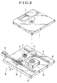
- Fig. 2 is an oblique view showing a disc (or sheet) driving deice to which this invention is applied as an embodiment thereof.
- Fig. 3 is a sectional view showing an embodiment of the invention.
- Figs. 4(a) and 4(b) show contact force distribution between a sheet-shaped recording medium and a pad, Fig. 4(a) showing the contact force distribution obtained by the embodiment of the invention and Fig. 4(b) showing the contact force distribution obtained by the conventional pad.
- Figs. 4(a) and 4(b) show contact force distribution between a sheet-shaped recording medium and a pad.
- FIG. 5(a) and 5(b) show the deformation of a sheet-shaped magnetic recording medium taking place when the sheet-shaped recording medium is sucked, Fig. 5(a) showing a deformation caused by the embodiment and Fig. 5(b) showing the deformation caused by the conventional device.
- Figs. 6(a) and 6(b) are a plan view and a sectional view showing another embodiment of the invention.
- Figs. 8(a) and 8(b) show distribution of pressure obtained between the sheet and the pad, Fig. 8(a) showing the pressure distribution obtained by the embodiment and Fig. 8(b) showing the pressure distribution obtained by the conventional device.
- Figs. 9(a) and 9(b) show sheet-sucking states obtained at projecting strip parts of the pads, Fig.
- Fig. 10 shows the distribution of a contact force obtained by the embodiment between the projecting strip parts of the pad and the sheet-shaped magnetic recording medium.
- Fig. 2 shows in an oblique view the recording or reproducing apparatus embodying this invention.
- a magnetic sheet 3 for recording (hereinafter referred to as the sheet) is rotatably stowed in a disc jacket 1.
- the sheet 3 has a center core 2 arranged in the middle part of the sheet 3 to be securely set on a spindle mounted on the rotation shaft of a spindle motor 10.
- a disc driving device 13 is arranged to drive and rotate the sheet 3 disposed within the disc jacket 1.
- the disc driving device 13 is provided with a magnetic recording or reproducing head 4 (hereinafter referred to as the head) and a pad 5 which is arranged around the head 4 to generate a sucking force (negative pressure) by the rotation of the sheet 3, as will be described in detail later.
- the head 4 and the pad 5 are secured by an adhesive to a head carriage 6 which is arranged to move the head 4.
- the head carriage 6 has an engaging part 7a of an elastic member 7 secured to one end thereof and is engaged by the engaging part 7a with a head moving mechanism which consists of a stepping motor 9 and a lead screw 8.
- the other end of the head carriage 6 is carried by a guide bar 12 in such a way as to be axially slidable on the guide bar 12.
- the head carriage 6 is thus arranged to be radially moved over the sheet 3 in the direction of arrow B to a given extent at a time.
- parts supporting the motor 9, the lead screw 8 and the guide bar 12 are omitted from the illustration.
- a spindle motor 10 is arranged to rotate the sheet 3 and has a chucking part 11 which is arranged to hold the center core 2 of the sheet 3.
- the sheet 3 is held by the chucking part 11 in such a way as to be freely detachable when the disc jacket 1 is demounted from the apparatus by a known means.
- the sheet 3 is rotated by the motor 10, the sheet 3 is sucked toward the pad 5 by a fluidic action of an air stream taking place between the sheet 3 and the pad 5. With the sheet 3 thus sucked, the sheet 3 comes into pressed contact with the head 4 to give an adequate touch of the head 4 on the sheet 3.
- Fig. 3 is a sectional view showing by way of example a pad arranged in accordance with this invention.
- the pad 30 is in a circular disc-like shape.
- the pad 30 comprises a first projecting strip part 33, a second projecting strip part 31, an annular groove part 32, a flat part 34 and a head mounting hole 38 which is formed in the flat part 34. These parts are arranged to surround the head 4. Cutout parts 35 and 36 are formed on the downstream side D of the pad 30.
- the head 4 is secured by means of an adhesive 39 to the inside of the head mounting hole 38 with the tip of the head 4 protruding further than the upper end of the projecting strip part 33 by scores of ⁇ m.
- the pad 30 is thus arranged to prevent any leak of air to ensure a stable state of negative pressure.
- the upper end sides of the second and first projecting strip parts 31 and 33 are formed aslant to have angles of inclination ⁇ 2 and ⁇ 1, respectively, as shown in Fig. 3.
- the sheet 3 is deformed in a natural manner along the sliding-contact faces 31a and 33a of the projecting strip parts 31 and 33.
- the possibility of the partial contact which has resulted from the conventional arrangement thus can be minimized by the embodiment of this invention.
- the embodiment gives a greater positive pressure than the conventional device on the upstream side U of the pad 30, so that the contact force of the sheet 3 on the pad 30 is lowered accordingly.
- the arrangement to form the sliding-contact faces 31a and 33a of the projecting strip parts 31 and 33 in a tapered shape weakens the positive pressure between the sheet 3 and the sliding-contact faces 31a and 33a of the pad 30.
- the thus weakened positive pressure allows the sheet 3 to be sufficiently sucked toward the pad 30 by the negative pressure developed at the groove part 32 and the flat part 34.
- the sheet 3 is deformed symmetrically with respect to the center of the head 4 when the gap part of the head 4 comes into contact with the sheet 3.
- the symmetric contact not only improves the head touch characteristic but also reduces the partial abrasion of the head 4.
- Figs. 4(a), 4(b), 5(a) and 5(b) show the results of simulation tests of the above-stated concept made in respect to fluidics and strength of materials.
- Figs. 4(a) and 4(b) show the distribution of the contact force between the sheet 3 and the pad 30.
- Figs. 5(a) and 5(b) are enlarged illustrations of the deformation in the deforming direction of the sheet 3.
- Figs. 4(b) and 5(b) show the results of simulation made for the conventional device
- the pad 100 strongly touches the radially outer and inner sides of the sheet 3 (upper and lower sides of the figure on the outer side of the projecting strip part 103. It has been ascertained through tests that the probability of occurrence of damages at the above-stated parts of the sheet 3 is high.
- the contact of the projecting strip part 33 with the sheet 3 is much more moderate. Meanwhile, the contact force is strong on the downstream side D on the inner side of the projecting strip part 31 and also is strong on the radially inner side of the sheet 3 (lower side of the figure).
- This result suggests that a better result is obtainable by setting the angle of inclination ⁇ 2 of the projecting strip part 31 at a smaller angle than the angle of inclination ⁇ 1 of the projecting strip part 33.
- the angles of inclination ⁇ 1 and ⁇ 2 should be in the following relation: ⁇ 1 ⁇ ⁇ 2 > 0 or ⁇ 1 > ⁇ 2 ⁇ 0
- the sheet 3 is apt to be damaged at its parts where the contact forces of the projecting strip parts 31 and 33 are strong. Therefore, the edges of the projecting strip parts 31 and 33 are preferably chamfered to a very small extent (scores of ⁇ m). These edges can be chamfered as desired by polishing the sliding-contact faces of the pad 30 through a flexible matter such as leather.
- the sheet 3 strongly touches the head 4 at a point on the upstream side U relative to the head 4. Hence, partial abrasion (wear) and an inadequate head touch tend to occur around this point. Whereas, in the case of Fig. 4(a), the sheet 3 strongly touches the central part of the head 4. In this case, therefore, the head 4 evenly wears away relative to the gap part of the head 4 to ensure an adequate head touch characteristic.
- the sheet 3 is away from the sliding-contact face 103a of the pad 100 on the downstream side D, as shown in Fig. 5(b).
- the deformation of the sheet 3 becomes asymmetric to cause the partial abrasion of the head 4.
- the sheet 3 is deformed nearly symmetrically relative to the head 4 on both the upstream and downstream sides U and D of the pad 30, as shown in Fig. 5(a). Therefore, the head 4 can be prevented from partially wearing.
- angles of inclination ⁇ 2 and ⁇ 1 of the sliding-contact faces 31a and 33a are arranged to be equal to each other. However, these angles may be arranged to be different from each other according to the distribution of pressure.
- the sliding-contact faces 33a and 31a of the first and second projecting strip parts 33 and 31 of the pad 30 are formed to be slanting upward toward the head 4. Therefore, the local contact forces of the sheet 3 on the head 4 and the pad 30 can be lowered and applied to their points which are symmetrically located. Therefore, the sheet 3 can be prevented from being damaged; jitters can be lessened; and the head 4 can be saved from partial abrasion.
- the arrangement of the embodiment thus greatly enhances the reliability and the durability of the apparatus.
- Figs. 6(a) and 6(b) show by way of example how the shape of the ridgelines of the projecting strip parts of the pad is defined.
- Fig. 6(a) shows the example in a plan view and Fig. 6(b) in a sectional view as taken along a center line of Fig. 6(a).
- the pad 60 is disposed around the magnetic head 4 and has a flat part 64 formed on one side of the pad 60 facing the magnetic sheet 3 (see Fig. 2).
- a slot (or hole) 68 is arranged in the middle part of the flat part 64 to allow the head 4 to be inserted therethrough.
- Concentric circular projecting strip parts 61 and 63 which protrude to a given height from the flat part 64 are spaced a given distance across an annular groove part 62.
- Cutout parts 65 and 66 which are arranged to eject an air stream generated by the rotation of the sheet 3 for controlling negative pressure developed by the pad 60 are formed at parts located on the downstream side D relative to the moving direction of the sheet 3 indicated by an arrow A.
- another cutout part 67 is formed in the projecting strip part 63 by cutting the projecting strip part 63 from its upper surface side down to a part which is at the same height as the flat part 64.
- Fig. 7 shows the sectional shape of the sliding-contact faces of the projecting strip parts 61 and 63 of the pad 60 which come into sliding contact with the sheet 3.
- This shape consists of a straight line and a plurality of circular arcs.
- the straight line part is located in the middle part "a".
- the both ends of the straight line part is moderately connected to circular arcs of a radius R1.
- Each of the arcs is further connected to an arc of a radius R2 smaller than R1.
- R1 : R2 10 : 1.
- the middle straight line part "a" may be replaced with an arc having a much greater radius than the radius R1 or R2.
- FIG. 8(a) shows the results of a fluidic analysis of pressure distribution thus obtained between the pad 60 and the sheet 3.
- the pressure distribution shown in Fig. 8(a) is obtained along a straight line A-A shown in Fig. 6(a).
- Points P1 to P8 shown in Fig. 8(a) correspond to points P1 to P8 shown in Fig. 6(a).
- Fig. 10 shows the results of an analysis of the state of contact of the sheet 3 with the whole pad 60.
- the sheet 3 is almost evenly touching the whole sliding-contact faces 61a and 63a of the projecting strip parts 61 and 63.
- each of the projecting strip parts 61 and 63 of the pad 60 consists of a nearly straight line part which is located on the side facing the sheet 3; and a plurality of arcs which continue from both ends of the nearly straight line part. Further, each of these arcs is formed to be consisting of a first arc which is of a radius R1 and continues from the nearly straight line part; and a second arc which is of a radius R2 and continues from the first arc.
- the radius R1 is arranged to be larger than the radius R2. This shape effectively reduces a sliding-contact resistance between the sheet 3 and the pad 60, so that a load on the spindle motor can be lessened and the motor can be prevented from unevenly rotating.
- the recording medium is not damaged; and an adequate head touch is obtainable. Therefore, the reliability of the recording or reproducing apparatus can be enhanced and energy can be saved.
- This embodiment has been described as being arranged to have the inner projecting strip part 63 and the outer projecting strip part 61 on one and the same plane for the sake of facilitating the description.
- a synergetic effect can be attained by a combination of the arrangement of this embodiment and that of the embodiment first described in the foregoing to give a still better recording or reproducing apparatus.
- a head supporting device arranged to surround a head, to include a first projecting strip part which protrudes on one side of the device facing a sheet-shaped recording medium and a second projecting strip part which is formed on the outer side of the first projecting strip part with a spacing part interposed between the first and second projecting strip parts and to suck the recording medium with negative pressure
- the sliding-contact faces of the first and second projecting strip parts are formed to be slanting upward toward the head, and a sectional shape of each of the projecting strip parts is composed of an approximately straight line which is on the recording-medium-facing side and a plurality of arcs which continue respectively from the two ends of the approximately straight line.
Landscapes
- Adjustment Of The Magnetic Head Position Track Following On Tapes (AREA)
- Supporting Of Heads In Record-Carrier Devices (AREA)
Applications Claiming Priority (4)
| Application Number | Priority Date | Filing Date | Title |
|---|---|---|---|
| JP37421/91 | 1991-03-04 | ||
| JP3742191A JPH04276355A (ja) | 1991-03-04 | 1991-03-04 | 磁気ヘッド支持装置 |
| JP286441/91 | 1991-10-31 | ||
| JP28644191A JPH05128703A (ja) | 1991-10-31 | 1991-10-31 | 記録または再生装置およびヘツド支持装置 |
Publications (3)
| Publication Number | Publication Date |
|---|---|
| EP0502463A2 true EP0502463A2 (de) | 1992-09-09 |
| EP0502463A3 EP0502463A3 (en) | 1992-12-23 |
| EP0502463B1 EP0502463B1 (de) | 1997-10-22 |
Family
ID=26376540
Family Applications (1)
| Application Number | Title | Priority Date | Filing Date |
|---|---|---|---|
| EP92103578A Expired - Lifetime EP0502463B1 (de) | 1991-03-04 | 1992-03-02 | Aufzeichnungs- oder Wiedergabegerät und kopftragende Vorrichtung |
Country Status (3)
| Country | Link |
|---|---|
| US (1) | US5432664A (de) |
| EP (1) | EP0502463B1 (de) |
| DE (1) | DE69222791T2 (de) |
Families Citing this family (3)
| Publication number | Priority date | Publication date | Assignee | Title |
|---|---|---|---|---|
| US6118626A (en) * | 1997-03-11 | 2000-09-12 | Massachusetts Institute Of Technology | Contact sheet recording with a self-acting negative air bearing |
| US6937435B2 (en) * | 2003-05-16 | 2005-08-30 | Quantum Corporation | Tape head with thin support surface and method of manufacture |
| US8332401B2 (en) * | 2004-10-01 | 2012-12-11 | Ricoh Co., Ltd | Method and system for position-based image matching in a mixed media environment |
Citations (9)
| Publication number | Priority date | Publication date | Assignee | Title |
|---|---|---|---|---|
| US4163267A (en) * | 1978-05-26 | 1979-07-31 | Burroughs Corporation | Flying head with compound-foil |
| JPS55157161A (en) * | 1979-05-21 | 1980-12-06 | Nippon Telegr & Teleph Corp <Ntt> | Magnetic disc device |
| JPS5954071A (ja) * | 1982-09-22 | 1984-03-28 | Fujitsu Ltd | 磁気ヘツド安定支持装置 |
| JPS60246010A (ja) * | 1984-05-21 | 1985-12-05 | Hitachi Ltd | 磁気テ−プ装置用磁気ヘツド |
| JPS619868A (ja) * | 1984-06-25 | 1986-01-17 | Olympus Optical Co Ltd | 磁気記録再生装置 |
| FR2579003A1 (fr) * | 1985-03-13 | 1986-09-19 | Canon Kk | Element stabilisateur de la tete d'un appareil d'enregistrement ou de reproduction |
| US4833556A (en) * | 1987-12-22 | 1989-05-23 | Eastman Kodak Company | Low drag stabilizer device for stabilizing the interface between a transducer and a moving medium |
| EP0333431A2 (de) * | 1988-03-18 | 1989-09-20 | Olympus Optical Co., Ltd. | Vorrichtung zur Stabilisierung von Kopf- und Daterträgern |
| GB2220787A (en) * | 1988-06-15 | 1990-01-17 | Sony Corp | Stabilizer block for a disc drive unit |
Family Cites Families (2)
| Publication number | Priority date | Publication date | Assignee | Title |
|---|---|---|---|---|
| JPH0256765A (ja) * | 1988-08-23 | 1990-02-26 | Alps Electric Co Ltd | 磁気ヘッド支持装置 |
| US5047884A (en) * | 1989-01-17 | 1991-09-10 | Fuji Photo Film Co., Ltd. | Magnetic head having a control portion for generating negative pressure |
-
1992
- 1992-03-02 EP EP92103578A patent/EP0502463B1/de not_active Expired - Lifetime
- 1992-03-02 DE DE69222791T patent/DE69222791T2/de not_active Expired - Fee Related
-
1994
- 1994-10-17 US US08/324,376 patent/US5432664A/en not_active Expired - Fee Related
Patent Citations (9)
| Publication number | Priority date | Publication date | Assignee | Title |
|---|---|---|---|---|
| US4163267A (en) * | 1978-05-26 | 1979-07-31 | Burroughs Corporation | Flying head with compound-foil |
| JPS55157161A (en) * | 1979-05-21 | 1980-12-06 | Nippon Telegr & Teleph Corp <Ntt> | Magnetic disc device |
| JPS5954071A (ja) * | 1982-09-22 | 1984-03-28 | Fujitsu Ltd | 磁気ヘツド安定支持装置 |
| JPS60246010A (ja) * | 1984-05-21 | 1985-12-05 | Hitachi Ltd | 磁気テ−プ装置用磁気ヘツド |
| JPS619868A (ja) * | 1984-06-25 | 1986-01-17 | Olympus Optical Co Ltd | 磁気記録再生装置 |
| FR2579003A1 (fr) * | 1985-03-13 | 1986-09-19 | Canon Kk | Element stabilisateur de la tete d'un appareil d'enregistrement ou de reproduction |
| US4833556A (en) * | 1987-12-22 | 1989-05-23 | Eastman Kodak Company | Low drag stabilizer device for stabilizing the interface between a transducer and a moving medium |
| EP0333431A2 (de) * | 1988-03-18 | 1989-09-20 | Olympus Optical Co., Ltd. | Vorrichtung zur Stabilisierung von Kopf- und Daterträgern |
| GB2220787A (en) * | 1988-06-15 | 1990-01-17 | Sony Corp | Stabilizer block for a disc drive unit |
Non-Patent Citations (5)
| Title |
|---|
| IBM TECHNICAL DISCLOSURE BULLETIN vol. 20, no. 1, June 1977, NEW YORK US page 37 G. W. BROCK 'Multiple slotted head contour' * |
| PATENT ABSTRACTS OF JAPAN vol. 10, no. 116 (P-452)(2173) 30 April 1986 & JP-A-60 246 010 ( HITACHI ) 5 December 1985 * |
| PATENT ABSTRACTS OF JAPAN vol. 10, no. 157 (P-464)(2213) 6 June 1986 & JP-A-61 9 868 ( OLYMPUS ) 17 January 1986 * |
| PATENT ABSTRACTS OF JAPAN vol. 5, no. 36 (P-51)(708) 7 March 1981 & JP-A-55 157 161 ( NIPPON DENSHIN DENWA KOSHA ) * |
| PATENT ABSTRACTS OF JAPAN vol. 8, no. 157 (P-288)(1594) 20 July 1984 & JP-A-59 54 071 ( FUJITSU ) 28 March 1984 * |
Also Published As
| Publication number | Publication date |
|---|---|
| DE69222791D1 (de) | 1997-11-27 |
| EP0502463B1 (de) | 1997-10-22 |
| DE69222791T2 (de) | 1998-03-12 |
| US5432664A (en) | 1995-07-11 |
| EP0502463A3 (en) | 1992-12-23 |
Similar Documents
| Publication | Publication Date | Title |
|---|---|---|
| US5086360A (en) | Constant flying height slider | |
| US4613921A (en) | Disk memory apparatus | |
| US4989107A (en) | Microfloppy disk drive with centering mechanism | |
| KR890005733A (ko) | 가요성 디스크 카셋트 | |
| US4620250A (en) | Transducer-to-medium stabilizing device at negative attack angle with respect to medium | |
| US4159494A (en) | Flexible disk in reversible cartridge | |
| EP0502463A2 (de) | Aufzeichnungs- oder Wiedergabegerät und kopftragende Vorrichtung | |
| US3947886A (en) | Flexible disc recording apparatus | |
| JPH05114227A (ja) | 情報記憶システムにおけるフレキシブル媒体の安定化方法及び装置 | |
| CS219341B2 (en) | Facility for supporting the rotating recording plate from flexible material | |
| US20030031113A1 (en) | Disk apparatus capable of automatically adjusting balance at the time of disk rotation | |
| EP0650163A2 (de) | Plattenantrieb | |
| US5014152A (en) | Flexible magnetic disc with a spring plate in the hub | |
| US6353590B1 (en) | Media stabilization for laser servowriting | |
| CA1084161A (en) | Data storage apparatus | |
| US4652960A (en) | Flexible disk recording and/or reproducing apparatus | |
| US5717551A (en) | Contact-type magnetic head having an integral control portion for generating negative pressure | |
| US4573368A (en) | Carriage driving apparatus | |
| US6680823B2 (en) | Moveable outer stop | |
| US5055955A (en) | Dual magnetic recording and reproduction heads with elastic mounting | |
| US5012366A (en) | Magnetic head supporting device | |
| US6543124B2 (en) | Voice coil motor attachment for a hard disc assembly | |
| EP0165431B1 (de) | Datenaufzeichnungsgerät mit einem magnetischen Wandlerkopf, der ohne Feineinstellung den für die Datenübertragung geeigneten Kontakt mit einer biegsamen Magnetplatte aufweist | |
| JPH05128703A (ja) | 記録または再生装置およびヘツド支持装置 | |
| EP0744744A2 (de) | Aufzeichnungsplattenzusammenbau in welchem eine Mehrzahl von Magnetplatten mittels einem Klemmring mit Schrumpfsitz oder Presspassung befestigt sind |
Legal Events
| Date | Code | Title | Description |
|---|---|---|---|
| PUAI | Public reference made under article 153(3) epc to a published international application that has entered the european phase |
Free format text: ORIGINAL CODE: 0009012 |
|
| AK | Designated contracting states |
Kind code of ref document: A2 Designated state(s): DE FR GB |
|
| PUAL | Search report despatched |
Free format text: ORIGINAL CODE: 0009013 |
|
| AK | Designated contracting states |
Kind code of ref document: A3 Designated state(s): DE FR GB |
|
| 17P | Request for examination filed |
Effective date: 19930505 |
|
| 17Q | First examination report despatched |
Effective date: 19950717 |
|
| GRAG | Despatch of communication of intention to grant |
Free format text: ORIGINAL CODE: EPIDOS AGRA |
|
| GRAH | Despatch of communication of intention to grant a patent |
Free format text: ORIGINAL CODE: EPIDOS IGRA |
|
| GRAH | Despatch of communication of intention to grant a patent |
Free format text: ORIGINAL CODE: EPIDOS IGRA |
|
| GRAA | (expected) grant |
Free format text: ORIGINAL CODE: 0009210 |
|
| AK | Designated contracting states |
Kind code of ref document: B1 Designated state(s): DE FR GB |
|
| PG25 | Lapsed in a contracting state [announced via postgrant information from national office to epo] |
Ref country code: FR Free format text: LAPSE BECAUSE OF FAILURE TO SUBMIT A TRANSLATION OF THE DESCRIPTION OR TO PAY THE FEE WITHIN THE PRESCRIBED TIME-LIMIT Effective date: 19971022 |
|
| REF | Corresponds to: |
Ref document number: 69222791 Country of ref document: DE Date of ref document: 19971127 |
|
| PG25 | Lapsed in a contracting state [announced via postgrant information from national office to epo] |
Ref country code: GB Free format text: LAPSE BECAUSE OF NON-PAYMENT OF DUE FEES Effective date: 19980302 |
|
| EN | Fr: translation not filed | ||
| PLBE | No opposition filed within time limit |
Free format text: ORIGINAL CODE: 0009261 |
|
| STAA | Information on the status of an ep patent application or granted ep patent |
Free format text: STATUS: NO OPPOSITION FILED WITHIN TIME LIMIT |
|
| 26N | No opposition filed | ||
| GBPC | Gb: european patent ceased through non-payment of renewal fee |
Effective date: 19980302 |
|
| PGFP | Annual fee paid to national office [announced via postgrant information from national office to epo] |
Ref country code: DE Payment date: 20060223 Year of fee payment: 15 |
|
| PG25 | Lapsed in a contracting state [announced via postgrant information from national office to epo] |
Ref country code: DE Free format text: LAPSE BECAUSE OF NON-PAYMENT OF DUE FEES Effective date: 20071002 |