EP0502385B1 - Procédé pour la production d'un revêtement bilatéral sur les pièces optiques - Google Patents
Procédé pour la production d'un revêtement bilatéral sur les pièces optiques Download PDFInfo
- Publication number
- EP0502385B1 EP0502385B1 EP92102989A EP92102989A EP0502385B1 EP 0502385 B1 EP0502385 B1 EP 0502385B1 EP 92102989 A EP92102989 A EP 92102989A EP 92102989 A EP92102989 A EP 92102989A EP 0502385 B1 EP0502385 B1 EP 0502385B1
- Authority
- EP
- European Patent Office
- Prior art keywords
- substrate
- coating
- electrode
- deposition
- evaporated
- Prior art date
- Legal status (The legal status is an assumption and is not a legal conclusion. Google has not performed a legal analysis and makes no representation as to the accuracy of the status listed.)
- Expired - Lifetime
Links
Images
Classifications
-
- C—CHEMISTRY; METALLURGY
- C03—GLASS; MINERAL OR SLAG WOOL
- C03C—CHEMICAL COMPOSITION OF GLASSES, GLAZES OR VITREOUS ENAMELS; SURFACE TREATMENT OF GLASS; SURFACE TREATMENT OF FIBRES OR FILAMENTS MADE FROM GLASS, MINERALS OR SLAGS; JOINING GLASS TO GLASS OR OTHER MATERIALS
- C03C17/00—Surface treatment of glass, not in the form of fibres or filaments, by coating
- C03C17/34—Surface treatment of glass, not in the form of fibres or filaments, by coating with at least two coatings having different compositions
- C03C17/3411—Surface treatment of glass, not in the form of fibres or filaments, by coating with at least two coatings having different compositions with at least two coatings of inorganic materials
- C03C17/3429—Surface treatment of glass, not in the form of fibres or filaments, by coating with at least two coatings having different compositions with at least two coatings of inorganic materials at least one of the coatings being a non-oxide coating
- C03C17/3464—Surface treatment of glass, not in the form of fibres or filaments, by coating with at least two coatings having different compositions with at least two coatings of inorganic materials at least one of the coatings being a non-oxide coating comprising a chalcogenide
- C03C17/3476—Surface treatment of glass, not in the form of fibres or filaments, by coating with at least two coatings having different compositions with at least two coatings of inorganic materials at least one of the coatings being a non-oxide coating comprising a chalcogenide comprising a selenide or telluride
-
- C—CHEMISTRY; METALLURGY
- C03—GLASS; MINERAL OR SLAG WOOL
- C03C—CHEMICAL COMPOSITION OF GLASSES, GLAZES OR VITREOUS ENAMELS; SURFACE TREATMENT OF GLASS; SURFACE TREATMENT OF FIBRES OR FILAMENTS MADE FROM GLASS, MINERALS OR SLAGS; JOINING GLASS TO GLASS OR OTHER MATERIALS
- C03C17/00—Surface treatment of glass, not in the form of fibres or filaments, by coating
- C03C17/001—General methods for coating; Devices therefor
-
- C—CHEMISTRY; METALLURGY
- C03—GLASS; MINERAL OR SLAG WOOL
- C03C—CHEMICAL COMPOSITION OF GLASSES, GLAZES OR VITREOUS ENAMELS; SURFACE TREATMENT OF GLASS; SURFACE TREATMENT OF FIBRES OR FILAMENTS MADE FROM GLASS, MINERALS OR SLAGS; JOINING GLASS TO GLASS OR OTHER MATERIALS
- C03C17/00—Surface treatment of glass, not in the form of fibres or filaments, by coating
- C03C17/34—Surface treatment of glass, not in the form of fibres or filaments, by coating with at least two coatings having different compositions
- C03C17/3411—Surface treatment of glass, not in the form of fibres or filaments, by coating with at least two coatings having different compositions with at least two coatings of inorganic materials
- C03C17/3417—Surface treatment of glass, not in the form of fibres or filaments, by coating with at least two coatings having different compositions with at least two coatings of inorganic materials all coatings being oxide coatings
-
- C—CHEMISTRY; METALLURGY
- C03—GLASS; MINERAL OR SLAG WOOL
- C03C—CHEMICAL COMPOSITION OF GLASSES, GLAZES OR VITREOUS ENAMELS; SURFACE TREATMENT OF GLASS; SURFACE TREATMENT OF FIBRES OR FILAMENTS MADE FROM GLASS, MINERALS OR SLAGS; JOINING GLASS TO GLASS OR OTHER MATERIALS
- C03C17/00—Surface treatment of glass, not in the form of fibres or filaments, by coating
- C03C17/34—Surface treatment of glass, not in the form of fibres or filaments, by coating with at least two coatings having different compositions
- C03C17/3411—Surface treatment of glass, not in the form of fibres or filaments, by coating with at least two coatings having different compositions with at least two coatings of inorganic materials
- C03C17/3429—Surface treatment of glass, not in the form of fibres or filaments, by coating with at least two coatings having different compositions with at least two coatings of inorganic materials at least one of the coatings being a non-oxide coating
- C03C17/3447—Surface treatment of glass, not in the form of fibres or filaments, by coating with at least two coatings having different compositions with at least two coatings of inorganic materials at least one of the coatings being a non-oxide coating comprising a halide
- C03C17/3452—Surface treatment of glass, not in the form of fibres or filaments, by coating with at least two coatings having different compositions with at least two coatings of inorganic materials at least one of the coatings being a non-oxide coating comprising a halide comprising a fluoride
-
- C—CHEMISTRY; METALLURGY
- C03—GLASS; MINERAL OR SLAG WOOL
- C03C—CHEMICAL COMPOSITION OF GLASSES, GLAZES OR VITREOUS ENAMELS; SURFACE TREATMENT OF GLASS; SURFACE TREATMENT OF FIBRES OR FILAMENTS MADE FROM GLASS, MINERALS OR SLAGS; JOINING GLASS TO GLASS OR OTHER MATERIALS
- C03C17/00—Surface treatment of glass, not in the form of fibres or filaments, by coating
- C03C17/34—Surface treatment of glass, not in the form of fibres or filaments, by coating with at least two coatings having different compositions
- C03C17/3411—Surface treatment of glass, not in the form of fibres or filaments, by coating with at least two coatings having different compositions with at least two coatings of inorganic materials
- C03C17/3429—Surface treatment of glass, not in the form of fibres or filaments, by coating with at least two coatings having different compositions with at least two coatings of inorganic materials at least one of the coatings being a non-oxide coating
- C03C17/3464—Surface treatment of glass, not in the form of fibres or filaments, by coating with at least two coatings having different compositions with at least two coatings of inorganic materials at least one of the coatings being a non-oxide coating comprising a chalcogenide
- C03C17/347—Surface treatment of glass, not in the form of fibres or filaments, by coating with at least two coatings having different compositions with at least two coatings of inorganic materials at least one of the coatings being a non-oxide coating comprising a chalcogenide comprising a sulfide or oxysulfide
-
- C—CHEMISTRY; METALLURGY
- C23—COATING METALLIC MATERIAL; COATING MATERIAL WITH METALLIC MATERIAL; CHEMICAL SURFACE TREATMENT; DIFFUSION TREATMENT OF METALLIC MATERIAL; COATING BY VACUUM EVAPORATION, BY SPUTTERING, BY ION IMPLANTATION OR BY CHEMICAL VAPOUR DEPOSITION, IN GENERAL; INHIBITING CORROSION OF METALLIC MATERIAL OR INCRUSTATION IN GENERAL
- C23C—COATING METALLIC MATERIAL; COATING MATERIAL WITH METALLIC MATERIAL; SURFACE TREATMENT OF METALLIC MATERIAL BY DIFFUSION INTO THE SURFACE, BY CHEMICAL CONVERSION OR SUBSTITUTION; COATING BY VACUUM EVAPORATION, BY SPUTTERING, BY ION IMPLANTATION OR BY CHEMICAL VAPOUR DEPOSITION, IN GENERAL
- C23C14/00—Coating by vacuum evaporation, by sputtering or by ion implantation of the coating forming material
- C23C14/06—Coating by vacuum evaporation, by sputtering or by ion implantation of the coating forming material characterised by the coating material
- C23C14/14—Metallic material, boron or silicon
- C23C14/20—Metallic material, boron or silicon on organic substrates
-
- C—CHEMISTRY; METALLURGY
- C23—COATING METALLIC MATERIAL; COATING MATERIAL WITH METALLIC MATERIAL; CHEMICAL SURFACE TREATMENT; DIFFUSION TREATMENT OF METALLIC MATERIAL; COATING BY VACUUM EVAPORATION, BY SPUTTERING, BY ION IMPLANTATION OR BY CHEMICAL VAPOUR DEPOSITION, IN GENERAL; INHIBITING CORROSION OF METALLIC MATERIAL OR INCRUSTATION IN GENERAL
- C23C—COATING METALLIC MATERIAL; COATING MATERIAL WITH METALLIC MATERIAL; SURFACE TREATMENT OF METALLIC MATERIAL BY DIFFUSION INTO THE SURFACE, BY CHEMICAL CONVERSION OR SUBSTITUTION; COATING BY VACUUM EVAPORATION, BY SPUTTERING, BY ION IMPLANTATION OR BY CHEMICAL VAPOUR DEPOSITION, IN GENERAL
- C23C14/00—Coating by vacuum evaporation, by sputtering or by ion implantation of the coating forming material
- C23C14/22—Coating by vacuum evaporation, by sputtering or by ion implantation of the coating forming material characterised by the process of coating
- C23C14/50—Substrate holders
- C23C14/505—Substrate holders for rotation of the substrates
-
- C—CHEMISTRY; METALLURGY
- C23—COATING METALLIC MATERIAL; COATING MATERIAL WITH METALLIC MATERIAL; CHEMICAL SURFACE TREATMENT; DIFFUSION TREATMENT OF METALLIC MATERIAL; COATING BY VACUUM EVAPORATION, BY SPUTTERING, BY ION IMPLANTATION OR BY CHEMICAL VAPOUR DEPOSITION, IN GENERAL; INHIBITING CORROSION OF METALLIC MATERIAL OR INCRUSTATION IN GENERAL
- C23C—COATING METALLIC MATERIAL; COATING MATERIAL WITH METALLIC MATERIAL; SURFACE TREATMENT OF METALLIC MATERIAL BY DIFFUSION INTO THE SURFACE, BY CHEMICAL CONVERSION OR SUBSTITUTION; COATING BY VACUUM EVAPORATION, BY SPUTTERING, BY ION IMPLANTATION OR BY CHEMICAL VAPOUR DEPOSITION, IN GENERAL
- C23C16/00—Chemical coating by decomposition of gaseous compounds, without leaving reaction products of surface material in the coating, i.e. chemical vapour deposition [CVD] processes
- C23C16/44—Chemical coating by decomposition of gaseous compounds, without leaving reaction products of surface material in the coating, i.e. chemical vapour deposition [CVD] processes characterised by the method of coating
- C23C16/50—Chemical coating by decomposition of gaseous compounds, without leaving reaction products of surface material in the coating, i.e. chemical vapour deposition [CVD] processes characterised by the method of coating using electric discharges
- C23C16/503—Chemical coating by decomposition of gaseous compounds, without leaving reaction products of surface material in the coating, i.e. chemical vapour deposition [CVD] processes characterised by the method of coating using electric discharges using dc or ac discharges
-
- C—CHEMISTRY; METALLURGY
- C03—GLASS; MINERAL OR SLAG WOOL
- C03C—CHEMICAL COMPOSITION OF GLASSES, GLAZES OR VITREOUS ENAMELS; SURFACE TREATMENT OF GLASS; SURFACE TREATMENT OF FIBRES OR FILAMENTS MADE FROM GLASS, MINERALS OR SLAGS; JOINING GLASS TO GLASS OR OTHER MATERIALS
- C03C2218/00—Methods for coating glass
- C03C2218/30—Aspects of methods for coating glass not covered above
- C03C2218/365—Coating different sides of a glass substrate
Definitions
- the present invention relates to a method for coating at least one workpiece rotating about an axis in a vacuum chamber by means of a plasma discharge for the deposition of a polymer layer and by thermal evaporation, and to a coating device for coating at least one workpiece.
- Such layers are used in particular in the ophthalmic field. In this area of application, the layers are exposed to particularly harsh environmental conditions. Layers such as anti-reflective layers must therefore adhere particularly well to the base. For this purpose, it is known that before the thermally vapor-deposited optically active layer or the layer system is applied, the substrate must be provided with an intermediate layer as an adhesion promoter, or must be etched. The adhesive layer mentioned must not impair the optical properties of the layer system and the lens. In particular, it must be transparent. This adhesive layer is of particular importance when coating plastic substrates.
- the present invention aims to propose a method or an arrangement with which it is possible to provide workpieces on both sides with plasma polymerization layers and thermally vapor-deposited optical layers in such a way that a high resistance of the coating is ensured, with great economy of the industrial production process.
- the invention is based on the knowledge known per se from the fact that the use of an adhesive layer deposited by plasma polymerization brings advantageous results for the subsequently evaporated layer.
- the thermal vapor deposition of optical layers takes place, as is known, in vacuum vapor deposition systems, where due to the required high coating uniformity, this is often dome-shaped on the entire workpiece carrier and is simultaneously rotated during the vapor deposition process.
- Such vapor deposition systems are described, for example, in the book “Coatings on glass” by HK Pulker, Verlag Elsevier, 1984, page 213.
- the treatment In systems with conventional glow electrodes, the treatment must first be carried out on one side, then the workpiece must be turned and then the treatment must be carried out on the back.
- the substrates mentioned during the treatment in this way, the layer applied after the workpiece has been rotated, do not have the same quality.
- the layer applied to the back can show cracks, be easily rubbed off or even flake off, which leads to the coating being completely unusable.
- the back of the workpiece is contaminated inadmissibly during the first plasma treatment. To avoid this, the back should be completely covered during treatment of the front. It is easy to see that this is very high in a commercial production process Expenses.
- the solution to this problem can be achieved by the procedure according to claim 1.
- the plasma polymerization layer must be deposited simultaneously and symmetrically on the front and back of the substrate. This simultaneous deposition on both sides of the workpiece results in the desired layer quality with high process economy.
- the first side is then coated by thermal evaporation, the system is flooded and opened, the workpiece is rotated, the system is evacuated again to coat the second side.
- the process economy can be further increased drastically.
- Process reliability is also increased considerably. Opening the system, manipulating the workpiece carrier and then pumping the system out to apply the next vapor deposition layers is very time-consuming and can jeopardize the economical implementation of the process. Opening the system between the evaporation steps can also cause a shift in the process conditions as well as contamination and particles. Interrupting the process and opening the vacuum system thus has, in addition to economic disadvantages, above all disadvantages with regard to the layer quality.
- a highly advantageous way to avoid this problem is to use a workpiece holder that rotates automatically can be done after the plasma polymerization process and the coating of the first side, without interrupting the vacuum, to then coat the back of the workpiece by means of thermal evaporation.
- Such a multilayer system can be composed, for example, in such a way that first a polymer layer is deposited on the substrate and then a first vapor deposition layer consisting of a certain material, whereupon further vapor deposition layers consisting of, for example, different materials can be applied.
- a further intermediate layer made of a polymer as an adhesive layer.
- polymer layers with a water-repellent and abrasion-resistant effect are used as a protective layer. Multiple layers of this type are advantageously formed in accordance with the procedure according to claim 3 or 4.
- the procedure and the use of the materials according to claim 5 are particularly suitable for the deposition of the plasma-polymerized layer.
- Monomers are used as the reaction gas used, such as organic compounds from, for example, aromatic and aliphatic hydrocarbons or, for example, organometallic compounds such as, for example, from organosilicon compounds.
- support gases are mixed with the plasma discharge in addition to the reaction gas for the polymerization.
- Oxygen, argon or even air are particularly suitable. With this admixture, the desired chemical composition of the reaction product can be set.
- the procedure according to the invention can furthermore influence the method with regard to deposition speed and also layer composition with the aid of magnetic fields for influencing or increasing the plasma density.
- Such magnetic fields can be generated with electromagnetic or with permanent magnets.
- These magnetic field generating means can be arranged both inside and outside the plasma reactor. A suitable effect is achieved if the magnetic flux density in the area of action in the vicinity of the electrodes and the substrate shows values of 50 to 500 Gauss. According to the invention, this procedure is characterized in accordance with claim 7.
- the plasma polymerization process and the immediately following evaporation process are carried out with the same workpiece holder in the same vacuum chamber. Since the entire arrangement is characterized by particular simplicity, it is not provided for reasons of economy to remove the electrodes for the vapor deposition process using a manipulation mechanism. During the evaporation process, part of the electrode that is exposed to the evaporation source is coated. The coating material which is deposited on the electrode will thus be lost to the workpiece holder and the workpieces located thereon. This will reduce the growth rate during the coating process. If rod-shaped electrodes are used, which are relatively thin, the losses are negligible, with larger electrodes the losses increase due to shadowing of the workpieces, which can make the process uneconomical.
- the electrodes and the leads are shielded according to the procedure of claim 12.
- the spread of the plasma is to be deliberately limited to the workpiece carrier.
- the supply line should be completely insulated and shielded, whereas the electrodes should only be insulated or shielded on the side facing away from the workpiece carrier.
- the procedure according to claim 12 increases the deposition rate of the polymerization layer and the reproducibility quite considerably and in many cases is decisive for the usability of the method.
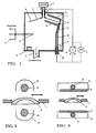
- FIG. 1 shows a cross section of process chamber 1 for producing vapor-deposited layers.
- the chamber 1 is connected to a vacuum pump via a pump nozzle 2.
- the workpiece holder 7, which can for example be plate-shaped, dome-shaped or also conical, is rotated via the vacuum rotary feedthrough 6 with the drive 5 during the processes.
- the workpieces or substrates 8, such as optical lenses, in particular plastic lenses, are carried by the workpiece holder 7.
- the workpiece holder 7 shown here conically has openings 8 for receiving the workpieces, so that the workpieces 8 are accessible on both sides for the deposition process.
- So-called turning devices are also advantageously used as workpiece holders. These are often segmented divided workpiece holders can then be rotated for coating the back using the turning mechanism.
- the vaporization of the workpieces 8 takes place in a known manner with the aid of evaporation sources 9, which are arranged at a certain distance from the workpiece holder 7.
- evaporation sources 9 which are arranged at a certain distance from the workpiece holder 7.
- the thermal evaporators such as electron beam evaporation sources or so-called boat evaporators are particularly suitable as coating sources 9.
- gases can be supplied in a known manner via a gas inlet or distribution device 3 to support the composition of the deposited layer.
- One or more gases are supplied via the connection points 4.
- the process gases such as monomers and auxiliary gases are admitted via this gas inlet device 3, 4.
- Process gas pressures used range from 1 millibar to 10 ⁇ 4 millibar depending on the desired process conditions.
- an electrode 10 is arranged which partially covers the electrically conductive workpiece holder 7 on both sides and which is connected to the supply line 18 via an insulated current feedthrough 15 with the electrical supplies 16, 17 is.
- the electrode 10 is arranged so that it extends from the edge of the workpiece holder 7 to approximately the center of rotation.
- the electrode 10 By rotating the workpiece holder 7 between the electrodes 10, it is ensured that the plasma discharge, which forms between the electrode 10 and the workpiece holder 7 acting as a counterelectrode, evenly sweeps over the workpieces 8.
- the distance between the electrodes should range from 1 to 20 cm. Good-quality and, in particular, economical process results are achieved when the electrode 10 is only exposed to the workpiece holder 7.
- the electrode 10 is provided on the side facing away from the workpiece holder 7 with a dark room shield 12, 13.
- This dark room shield is, for example via an electrical connection 14, an electrically conductive potential surface which connects to ground or system potential and is at a distance from the electrodes 10, which ensures the function of a dark room shield in a known manner and thus depends on the set process gas pressure.
- the distances are in the range of a few millimeters.
- the supply line 18 to the electrodes is completely shielded by means of a dark room shield 11. Instead of such dark room shields, the use of insulators such as ceramics is also possible.
- the electrode 10 is supplied with an electrical voltage by the generators 16, 17.
- voltage values from 200 volts to about 5000 volts are possible.
- the polarity of the connected electrode 10 can be negative or positive with respect to the structure of the deposited polymer layer with respect to the workpiece holder 7.
- the workpiece holder is usually electrically connected to the recipient wall.
- the same arrangement can also be used in a known manner in order to carry out ion etching with the aid of a pure noble gas discharge prior to the plasma polymerization deposition process.
- the substrate can optionally be etched if the workpiece holder polarity is negative or, for example, if the workpiece holder polarity is positive, it can be germinated with electrode material.
- the plasma polymerization process can then be carried out without interrupting the process by supplying the appropriate process gases.
- a direct current discharge it is also possible to generate an alternating current discharge.
- the electrode 10 is fed with an alternating current generator 17. Frequencies from 50 hertz to a few megahertz are particularly suitable for carrying out the method according to the invention.
- the electrode 10 can be designed with respect to the workpiece holder in two electrically separate parts which are fed separately with two generators, which allows the process to be finely controlled Adjust the setting of the electrical parameters. In this case, it can be advantageous to arrange the workpiece holder in an isolated manner with respect to the chamber 1 and to operate it in a so-called bias mode via a separate supply with respect to the electrodes 10 and the vacuum chamber 1.
- the effectiveness of the method can also be increased by using magnetic fields in the area of the plasma discharge, which increases the plasma density and thus increases the deposition rate.
- the use of magnetic fields can also be advantageous because it lowers the discharge voltage, which significantly simplifies the electrode installation and allows the use of more economical supplies.
- Favorable results are achieved if permanent magnets are used which are arranged in the electrode area and if a magnetic flux density in the discharge area between the electrode 10 and the workpiece 7 of 50 to 500 Gauss is achieved. With such arrangements, discharge voltage values of 200 to 1500 volts are possible.
- the magnetic fields can of course also be generated with electromagnetic coils.
- FIG. 2 shows a preferred embodiment in cross section through the electrode 10 and the dark room shields 12 and 13 and through the workpiece holder 7 with a workpiece 8.
- the rod-shaped electrode 10, for example 10 mm in diameter, is at a distance of several centimeters opposite the workpiece carrier 7, the dark room shields 12 and 13 enclosing the electrode 10 on the side facing away from the workpiece in a U-shape.
- the discharge is thus concentrated between the electrode 10 and the workpiece holder 7. On the one hand, this improves the homogeneity of the deposition process and, on the other hand, prevents impermissible impurities which would be deposited on the substrate from the vacuum chamber in the event of extended plasma discharges.
- a flat electrode 10 can be advantageous over rod-shaped electrodes.
- the use of a large-area electrode has 10 advantages.
- Figure 3 shows the arrangement of a large-area electrode in cross section.
- a surface coverage of the workpiece carrier 7 by the electrode 10 of more than 50% is no longer economical.
- the lens was anti-reflective without interrupting the vacuum.
- the anti-reflective coating was carried out by evaporating 4 layers in the following sequence: TiO2, SiO2, TiO2, SiO2.
- the second anti-reflective coating Lens side was done in the same way after rotating the lens with an automatic turning device. The same procedure can also be carried out successfully if the lenses are turned manually after the anti-reflective coating on the first side after opening the system in order to anti-reflective coating the second side.
- the lenses were subjected to a durability test, i.e. these were immersed 6 times in a boiling aqueous 4.5% NaCl solution for 2 minutes and then in 20 degrees water.
- the layers showed no visible damage, e.g. Cracks or peeling.
- the plasma polymerization layer and the anti-reflective layer were applied first on one side and then on the other side of the lens.
- a simple rod-shaped electrode was used for the deposition of the polymerization layer, as is customary in the prior art.
- the anti-reflective layer was then evaporated. The lens was then turned over to again deposit the plasma polymerization layer on the back and to apply the anti-reflective layer thereon.
- the lens was subjected to the same test as described in Example 1.
- the lens side, which one first coated, showed the same resistance as the coated lens sides according to Example 1.
- the second lens side, which was coated after turning, already showed after a first test cycle, ie after a single immersion in the aqueous 4.5% NaCl -Solution, considerable delamination. Ie the second lens side shows a completely unusable coating.
- a procedure according to the known prior art for the adhesive coating of lenses on both sides in the present conventional system configuration does not lead to usable results.
- a generation of adhesive layers on both sides of the lenses would only be possible according to the state of the art procedure if one side of the lens was covered during the coating of the other side of the lens.
- a procedure would, however, require that the lens on the back be carefully covered.
- a first possibility is that after treating the first side, the system is opened, the cover is removed and the lens is rotated in order to be able to coat the second side.
- a second possibility is the use of a complicated automatic movable covering device, which has to be actuated before each turning of the substrates. Such a procedure or device is not economically justifiable and leads to a reduction in the quality of the products due to the complex manipulations.
- Both sides of the lens showed a strongly hydrophobic behavior, which was noticeable by the fact that the lens was easier to clean.
- the lens was subjected to the same test as described in Example 1.
- the layers showed no visible damage, e.g. Cracks or peeling.
Claims (14)
- Procédé de revêtement d'au moins une pièce à traiter (8), tournant autour d'un axe dans une chambre de vide (1), au moyen d'une décharge plasma destinée à déposer une couche de polymérisat et au moyen d'une évaporation thermique, caractérisé en ce que la couche de polymérisat est déposée simultanément sur les deux côtés de la pièce à traiter (8) et que des couches déposées par évaporation thermique sont ensuite appliquées sur les deux côtés de la pièce à traiter (8), un premier côté étant revêtu en premier lieu, la pièce à traiter étant ensuite tournée et le deuxième côté étant ensuite revêtu.
- Procédé selon la revendication 1, caractérisé en ce que le revêtement s'effectue sans interruption de vide et que l'application des couches appliquées par évaporation sur les deux côtés se produit par rotation de la pièce à traiter (8) dans la chambre de vide (1).
- Procédé selon la revendication 1 ou 2, caractérisé en ce que le nombre des couches appliquées est supérieur à deux.
- Procédé selon la revendication 3, caractérisé en ce qu'une première couche de polymérisat est déposée en premier lieu et qu'au moins une couche déposée par évaporation thermique et une couche de polymérisat qui sert de couche de protection sont ensuite déposées.
- Procédé selon l'une des revendications 1 à 4, caractérisé en ce que des gaz monomères venant de composés organiques ou organométalliques sont utilisés pour le dépôt de couches qui se polymérisent par plasma et que des métaux ou des composés métalliques des oxydes, fluorures, sulfures, tellurures et séléniures sont évaporés pour l'application des couches appliquées par évaporation.
- Procédé selon l'une des revendications 1 à 5, caractérisé en ce que des gaz monomères venant de composés organo-siliciques sont utilisés pour le dépôt de couches qui se polymérisent par plasma et que des métaux ou des composés métalliques des oxydes, fluorures, sulfures, tellurures et séléniures sont évaporés pour l'application des couches appliquées par évaporation.
- Procédé selon la revendication 5 ou 6, caractérisé en ce que des gaz additionnels, par exemple O₂, Ar, de l'air, H₂, H₂0, N₂, NO, NO₂ et/ou He sont ajoutés pour la décharge plasma des gaz polymérisables.
- Procédé selon l'une des revendications 1 à 7, caractérisé en ce que des champs magnétiques sont utilisés pour élever la densité de plasma.
- Procédé selon l'une des revendications 1 à 8, caractérisé en ce que les couches sont déposées sur des lentilles ophtalmiques.
- Installation de revêtement destiné à revêtir au moins une pièce à traiter (8), caractérisé en ce qu'il comprend:- une chambre de vide (1) pourvue d'une installation de pompe (2) et d'une installation d'introduction de gaz (4, 3);- un support (7) de pièce à traiter électriquement conducteur tournant autour d'un axe;- au moins une électrode électroluminescente (10) disposée en direction axiale sur les deux côtés de la voie de support de pièce à traiter et recouvrant au moins partiellement cette voie;- au moins une source d'évaporation thermique (9), ainsi que- une alimentation en courant (16, 17) pour engendrer une décharge plasma entre l'électrode électroluminescente (10) et le support (7) de pièce à traiter.
- Installation de revêtement selon la revendication 10 destinée à revêtir la pièce à traiter (8) selon le procédé conforme à l'une des revendications 1 à 9.
- Installation de revêtement selon la revendication 10 ou 11, caractérisée en ce que l'électrode (10) recouvre au maximum la moitié du support de pièce à traiter.
- Installation de revêtement selon la revendication 12, caractérisée en ce qu'un écran d'espace sombre (11, 12, 13) et/ou des isolants recouvrent sensiblement en totalité des lignes électriques (18) et recouvrent les électrodes électroluminescentes (10) sur le côté opposé à la pièce à traiter.
- Utilisation du dispositif de revêtement selon l'une des revendications 10 à 13 pour le revêtement de lentilles ophtalmiques, de préférence selon un procédé conforme aux revendications 1 à 9.
Applications Claiming Priority (2)
| Application Number | Priority Date | Filing Date | Title |
|---|---|---|---|
| CH659/91 | 1991-03-05 | ||
| CH65991 | 1991-03-05 |
Publications (2)
| Publication Number | Publication Date |
|---|---|
| EP0502385A1 EP0502385A1 (fr) | 1992-09-09 |
| EP0502385B1 true EP0502385B1 (fr) | 1995-06-21 |
Family
ID=4192155
Family Applications (1)
| Application Number | Title | Priority Date | Filing Date |
|---|---|---|---|
| EP92102989A Expired - Lifetime EP0502385B1 (fr) | 1991-03-05 | 1992-02-22 | Procédé pour la production d'un revêtement bilatéral sur les pièces optiques |
Country Status (3)
| Country | Link |
|---|---|
| US (1) | US5211759A (fr) |
| EP (1) | EP0502385B1 (fr) |
| DE (1) | DE59202577D1 (fr) |
Cited By (2)
| Publication number | Priority date | Publication date | Assignee | Title |
|---|---|---|---|---|
| DE19914129A1 (de) * | 1999-03-27 | 2000-09-28 | Forschungszentrum Juelich Gmbh | Verfahren zum doppelseitigen Beschichten eines Substrates mit insbesondere einem HTS-Material durch Materialabscheidung und Vorrichtung zur Durchführung des Verfahrens |
| WO2017077106A1 (fr) | 2015-11-05 | 2017-05-11 | Bühler Alzenau Gmbh | Dispositif et procédé de dépôt sous vide |
Families Citing this family (34)
| Publication number | Priority date | Publication date | Assignee | Title |
|---|---|---|---|---|
| CH685348A5 (de) * | 1992-05-08 | 1995-06-15 | Balzers Hochvakuum | Vakuumbeschichtungsanlage mit drehgetriebenem Substratträger. |
| JP3204801B2 (ja) * | 1993-06-18 | 2001-09-04 | 富士写真フイルム株式会社 | 真空グロー放電処理装置及び処理方法 |
| DE4404690A1 (de) * | 1994-02-15 | 1995-08-17 | Leybold Ag | Verfahren zur Erzeugung von Sperrschichten für Gase und Dämpfe auf Kunststoff-Substraten |
| GB9405442D0 (en) * | 1994-03-19 | 1994-05-04 | Applied Vision Ltd | Apparatus for coating substrates |
| FR2718734B1 (fr) * | 1994-04-13 | 1996-07-12 | Cfei Co Fr Electrotherm Ind | Procédé et dispositif de coloration de verre. |
| FR2731370B1 (fr) * | 1995-03-07 | 1997-06-06 | Cie Generale D Optique Essilor | Procede pour le depot assiste par plasma d'au moins une couche mince sur un substrat a deux faces, et reacteur correspondant |
| US5753319A (en) * | 1995-03-08 | 1998-05-19 | Corion Corporation | Method for ion plating deposition |
| US5789040A (en) * | 1997-05-21 | 1998-08-04 | Optical Coating Laboratory, Inc. | Methods and apparatus for simultaneous multi-sided coating of optical thin film designs using dual-frequency plasma-enhanced chemical vapor deposition |
| DE19802506A1 (de) * | 1998-01-23 | 1999-07-29 | Leybold Systems Gmbh | Metallhaltige Barriereschicht für Verpackungsmaterial und Verfahren zur Herstellung einer metallhaltigen Barriereschicht für Verpackungsmaterial |
| DE19802333A1 (de) * | 1998-01-23 | 1999-07-29 | Leybold Systems Gmbh | Barriereschicht für Verpackungsmaterial und Verfahren zur Herstellung einer Barriereschicht für Verpackungsmaterial |
| JP2000017457A (ja) * | 1998-07-03 | 2000-01-18 | Shincron:Kk | 薄膜形成装置および薄膜形成方法 |
| US6964731B1 (en) * | 1998-12-21 | 2005-11-15 | Cardinal Cg Company | Soil-resistant coating for glass surfaces |
| US6974629B1 (en) | 1999-08-06 | 2005-12-13 | Cardinal Cg Company | Low-emissivity, soil-resistant coating for glass surfaces |
| US6660365B1 (en) * | 1998-12-21 | 2003-12-09 | Cardinal Cg Company | Soil-resistant coating for glass surfaces |
| TR200102186T2 (tr) * | 1998-12-21 | 2001-11-21 | Cardinal Ig Company | Cam yüzeyleri için kire-dayanıklı kaplamalar |
| FR2834712B1 (fr) * | 2002-01-14 | 2004-12-17 | Essilor Int | Procede de traitement d'un verre ophtalmique |
| FR2856056B1 (fr) * | 2003-06-13 | 2009-07-03 | Essilor Int | Procede de traitement d'un verre apte au debordage. |
| US7250197B2 (en) * | 2003-08-25 | 2007-07-31 | Bausch & Lomb Incorporated | Plasma treatment of contact lens and IOL |
| FR2860306B1 (fr) * | 2003-09-26 | 2006-09-01 | Essilor Int | Lentille ophtalmique recouverte d'un film electrostatique et procede de debordage d'une telle lentille |
| US20050181177A1 (en) * | 2004-02-18 | 2005-08-18 | Jamie Knapp | Isotropic glass-like conformal coatings and methods for applying same to non-planar substrate surfaces at microscopic levels |
| DE602005003228T2 (de) | 2004-07-12 | 2008-08-28 | Cardinal Cg Co., Eden Prairie | Wartungsarme beschichtungen |
| EP1828072B1 (fr) * | 2004-11-15 | 2016-03-30 | Cardinal CG Company | Procedes pour deposer des revetements presentant des structures ordonnees |
| DE102004056965A1 (de) * | 2004-11-25 | 2006-06-08 | Rodenstock Gmbh | Verbesserung der Haftung von hydrophoben Beschichtungen auf Brillengläsern |
| US7923114B2 (en) | 2004-12-03 | 2011-04-12 | Cardinal Cg Company | Hydrophilic coatings, methods for depositing hydrophilic coatings, and improved deposition technology for thin films |
| US8092660B2 (en) | 2004-12-03 | 2012-01-10 | Cardinal Cg Company | Methods and equipment for depositing hydrophilic coatings, and deposition technologies for thin films |
| DE102005014031A1 (de) * | 2005-03-23 | 2006-09-28 | Leybold Optics Gmbh | Beschichtetes Substrat mit einer temporären Schutzschicht sowie Verfahren zu seiner Herstellung |
| US20070141358A1 (en) | 2005-12-19 | 2007-06-21 | Essilor International Compagnie Generale D'optique | Method for improving the edging of an optical article by providing a temporary layer of an organic material |
| US7989094B2 (en) | 2006-04-19 | 2011-08-02 | Cardinal Cg Company | Opposed functional coatings having comparable single surface reflectances |
| US20080011599A1 (en) | 2006-07-12 | 2008-01-17 | Brabender Dennis M | Sputtering apparatus including novel target mounting and/or control |
| US7820309B2 (en) | 2007-09-14 | 2010-10-26 | Cardinal Cg Company | Low-maintenance coatings, and methods for producing low-maintenance coatings |
| EP2145979A1 (fr) * | 2008-07-16 | 2010-01-20 | AGC Flat Glass Europe SA | Procédé et installation pour le dépôt de couches sur les deux faces d'un substrat de façon simultanée |
| EP3541762B1 (fr) | 2016-11-17 | 2022-03-02 | Cardinal CG Company | Technologie de revêtement à dissipation statique |
| US10820402B2 (en) * | 2017-03-15 | 2020-10-27 | Plasmatica Ltd. | Device and method for treating lenses |
| US11243393B2 (en) * | 2017-03-15 | 2022-02-08 | Plasmatica Ltd. | Device and method for treating lenses |
Family Cites Families (5)
| Publication number | Priority date | Publication date | Assignee | Title |
|---|---|---|---|---|
| US2397207A (en) * | 1943-10-29 | 1946-03-26 | Rca Corp | Lens coating apparatus |
| US3713869A (en) * | 1971-06-09 | 1973-01-30 | Jenaer Glaswerk Schott & Gen | Method of applying hard inorganic layers to plastics |
| NL7202331A (fr) * | 1972-01-24 | 1973-07-26 | ||
| NL7205670A (fr) * | 1972-03-16 | 1973-09-18 | ||
| US4512284A (en) * | 1983-12-19 | 1985-04-23 | Rca Corporation | Glow discharge apparatus for use in coating a disc-shaped substrate |
-
1992
- 1992-02-22 DE DE59202577T patent/DE59202577D1/de not_active Expired - Fee Related
- 1992-02-22 EP EP92102989A patent/EP0502385B1/fr not_active Expired - Lifetime
- 1992-02-26 US US07/841,721 patent/US5211759A/en not_active Expired - Fee Related
Cited By (3)
| Publication number | Priority date | Publication date | Assignee | Title |
|---|---|---|---|---|
| DE19914129A1 (de) * | 1999-03-27 | 2000-09-28 | Forschungszentrum Juelich Gmbh | Verfahren zum doppelseitigen Beschichten eines Substrates mit insbesondere einem HTS-Material durch Materialabscheidung und Vorrichtung zur Durchführung des Verfahrens |
| DE19914129C2 (de) * | 1999-03-27 | 2001-04-05 | Forschungszentrum Juelich Gmbh | Verfahren zum doppelseitigen Beschichten eines Substrates mit insbesondere einem Hochtemperatursupraleiter-Material durch Materialabscheidung und Vorrichtung zur Durchführung des Verfahrens |
| WO2017077106A1 (fr) | 2015-11-05 | 2017-05-11 | Bühler Alzenau Gmbh | Dispositif et procédé de dépôt sous vide |
Also Published As
| Publication number | Publication date |
|---|---|
| US5211759A (en) | 1993-05-18 |
| EP0502385A1 (fr) | 1992-09-09 |
| DE59202577D1 (de) | 1995-07-27 |
Similar Documents
| Publication | Publication Date | Title |
|---|---|---|
| EP0502385B1 (fr) | Procédé pour la production d'un revêtement bilatéral sur les pièces optiques | |
| EP0478909B1 (fr) | Procédé et appareillage pour la fabrication d'une couche de diamant | |
| EP0228394B1 (fr) | Procede et appareil d'enduction de substrats par decharge de plasma | |
| EP0205028B1 (fr) | Appareil pour le dépôt de couches minces sur un substrat | |
| EP0285745B1 (fr) | Procédé et dispositifs de déposition sous vide utilisant une décharge électrique | |
| DE2614951C3 (de) | Verfahren zur Herstellung einer Flüssigkristall-Zelle | |
| EP0394661A1 (fr) | Procédé pour revêtir au moins partiellement des outils au moyen d'une méthode de déposition chimique en phase vapeur associée à une pulvérisation | |
| DE19902146C2 (de) | Verfahren und Einrichtung zur gepulsten Plasmaaktivierung | |
| DE2608415A1 (de) | Verfahren zur beschichtung eines substrats mit einer lage polymeren materials | |
| EP2735018B1 (fr) | Procédé et dispositif de fabrication de couches pauvres en particules sur des substrats | |
| EP0812368A1 (fr) | Procede de pulverisation reactive | |
| DE19936199A1 (de) | Magnetronreaktor zum Bereitstellen einer hochdichten, induktiv gekoppelten Plasmaquelle zum Sputtern von Metallfilmen und Dielektrischen Filmen | |
| DE19740793A1 (de) | Verfahren zur Beschichtung von Oberflächen mittels einer Anlage mit Sputterelektroden | |
| DE10100746A1 (de) | Vorrichtung und Verfahren zum Bilden von Filmen | |
| DE10196150B4 (de) | Magnetron-Sputtervorrichtung und Verfahren zum Steuern einer solchen Vorrichtung | |
| DE102008064134B4 (de) | Verfahren zur Beschichtung von Gegenständen mittels eines Niederdruckplasmas | |
| EP0867036B1 (fr) | Procede et dispositif pour le pretraitement de substrats | |
| EP0776987B1 (fr) | Appareillage de revêtement sous vide avec un creuset pour recevoir le matériau à évaporer dans la chambre à vide | |
| DE4239511A1 (de) | Verfahren und Vorrichtung zum Beschichten von Substraten | |
| EP0794014B1 (fr) | Procédé et appareil pour polymériser avec un plasma à haute fréquence | |
| DE102008022145B4 (de) | Vorrichtung und Verfahren zum Hochleistungs-Puls-Gasfluß-Sputtern | |
| EP0424620B1 (fr) | Procédé et dispositif pour le revêtement par moyen chimique des surfaces opposés d'une pièce | |
| DE2624005A1 (de) | Verfahren zum aufbringen von duennen schichten nach dem ion-plating- verfahren und vorrichtung dazu | |
| DE19610253A1 (de) | Zerstäubungseinrichtung | |
| DE2612098A1 (de) | Verfahren zum gleichmaessigen metallisieren eines substrats |
Legal Events
| Date | Code | Title | Description |
|---|---|---|---|
| PUAI | Public reference made under article 153(3) epc to a published international application that has entered the european phase |
Free format text: ORIGINAL CODE: 0009012 |
|
| 17P | Request for examination filed |
Effective date: 19920222 |
|
| AK | Designated contracting states |
Kind code of ref document: A1 Designated state(s): CH DE FR IT LI |
|
| 17Q | First examination report despatched |
Effective date: 19940303 |
|
| GRAA | (expected) grant |
Free format text: ORIGINAL CODE: 0009210 |
|
| AK | Designated contracting states |
Kind code of ref document: B1 Designated state(s): CH DE FR IT LI |
|
| REF | Corresponds to: |
Ref document number: 59202577 Country of ref document: DE Date of ref document: 19950727 |
|
| ITF | It: translation for a ep patent filed |
Owner name: ING. ZINI MARANESI & C. S.R.L. |
|
| ET | Fr: translation filed | ||
| PLBE | No opposition filed within time limit |
Free format text: ORIGINAL CODE: 0009261 |
|
| STAA | Information on the status of an ep patent application or granted ep patent |
Free format text: STATUS: NO OPPOSITION FILED WITHIN TIME LIMIT |
|
| 26N | No opposition filed | ||
| PGFP | Annual fee paid to national office [announced via postgrant information from national office to epo] |
Ref country code: FR Payment date: 20020212 Year of fee payment: 11 |
|
| PGFP | Annual fee paid to national office [announced via postgrant information from national office to epo] |
Ref country code: DE Payment date: 20020306 Year of fee payment: 11 |
|
| PGFP | Annual fee paid to national office [announced via postgrant information from national office to epo] |
Ref country code: CH Payment date: 20020529 Year of fee payment: 11 |
|
| PG25 | Lapsed in a contracting state [announced via postgrant information from national office to epo] |
Ref country code: LI Free format text: LAPSE BECAUSE OF NON-PAYMENT OF DUE FEES Effective date: 20030228 Ref country code: CH Free format text: LAPSE BECAUSE OF NON-PAYMENT OF DUE FEES Effective date: 20030228 |
|
| PG25 | Lapsed in a contracting state [announced via postgrant information from national office to epo] |
Ref country code: DE Free format text: LAPSE BECAUSE OF NON-PAYMENT OF DUE FEES Effective date: 20030902 |
|
| REG | Reference to a national code |
Ref country code: CH Ref legal event code: PL |
|
| PG25 | Lapsed in a contracting state [announced via postgrant information from national office to epo] |
Ref country code: FR Free format text: LAPSE BECAUSE OF NON-PAYMENT OF DUE FEES Effective date: 20031031 |
|
| REG | Reference to a national code |
Ref country code: FR Ref legal event code: ST |
|
| PG25 | Lapsed in a contracting state [announced via postgrant information from national office to epo] |
Ref country code: IT Free format text: LAPSE BECAUSE OF NON-PAYMENT OF DUE FEES;WARNING: LAPSES OF ITALIAN PATENTS WITH EFFECTIVE DATE BEFORE 2007 MAY HAVE OCCURRED AT ANY TIME BEFORE 2007. THE CORRECT EFFECTIVE DATE MAY BE DIFFERENT FROM THE ONE RECORDED. Effective date: 20050222 |