EP0502185B1 - Valve assembly for nozzle/plate assembly - Google Patents
Valve assembly for nozzle/plate assembly Download PDFInfo
- Publication number
- EP0502185B1 EP0502185B1 EP91919361A EP91919361A EP0502185B1 EP 0502185 B1 EP0502185 B1 EP 0502185B1 EP 91919361 A EP91919361 A EP 91919361A EP 91919361 A EP91919361 A EP 91919361A EP 0502185 B1 EP0502185 B1 EP 0502185B1
- Authority
- EP
- European Patent Office
- Prior art keywords
- assembly
- plate
- clamp ring
- main frame
- spring
- Prior art date
- Legal status (The legal status is an assumption and is not a legal conclusion. Google has not performed a legal analysis and makes no representation as to the accuracy of the status listed.)
- Expired - Lifetime
Links
Images

Classifications
-
- B—PERFORMING OPERATIONS; TRANSPORTING
- B22—CASTING; POWDER METALLURGY
- B22D—CASTING OF METALS; CASTING OF OTHER SUBSTANCES BY THE SAME PROCESSES OR DEVICES
- B22D41/00—Casting melt-holding vessels, e.g. ladles, tundishes, cups or the like
- B22D41/50—Pouring-nozzles
Definitions
- This invention relates to a valve assembly of the type used primarily in the teeming of steel.
- Such valves are known from US-A-4,582,232 and US-A-4,573,616.
- US-A-4,063,668 shows refractory inserts in a valve which are encased in a metal jacket.
- An improved refractory is shown in the firstmentioned U.S. Patents, where there is no metal encasement of the refractory, and the refractory side edges are tapered in such a fashion that they receive clamping members which exert a force component both centrally and downwardly simultaneously to retain the refractory against expansion and cracking due to thermal shock and to provide a downward component (in some instances upward where the top plate is clamped) to hold the refractory to the valve.
- the means for clamping the refractory to the mounting plate when located upstream of the stationary plate has required one or more elements which have to be bolted to a mounting plate. This takes time, and the bolts are subject to the highly corrosive environment of the teeming of steel. What is desirable is to develop a clamp which is virtually automatic in nature and wherein the force of the springs and the clamping to the main frame is employed to urge an external clamping action against the periphery of the refractory.
- a valve assembly comprising, in combination, an unencased refractory nozzle/plate assembly for insertion into a vessel and a depending tube assembly in which sidewalls of the nozzle/plate assembly are continuous and continuously taper outwardly from a downstream face of the nozzle/plate assembly toward the vessel, a mounting plate for securing the valve assembly to the vessel, a main frame for yieldably urging a depending tube assembly having an upstream flat face in face-to-face relationship with an outer face of the unencased plate, a clamp ring for insertion interiorly of the main frame, having tapered sidewalls for a mating engagement with the unencased plate sidewalls and a spring assembly, characterised in that said spring assembly is for seating in the main frame and bearing against the clamp ring, there being clamping means for clampingly securing the main frame to the mounting plate and means on the clamp ring for securing it to the main frame; and in that said unencased nozzle/plate assembly,
- a clamp ring assembly for use in a valve for teeming metal from a vessel, said clamp ring assembly comprising a frame with clamping means for removably securing the frame to a mounting plate for the valve, a clamp ring proportioned to surround a stationary refractory having tapered walls, characterised in that said clamp ring has spring engaging means on its periphery, a spring assembly mounted in the frame and secured to the clamp ring spring engaging means, the foregoing being all proportioned and orientated to permit preloading of the clamp ring prior to closing the frame onto the mounting plate by means of the clamping means, whereby a first preload is applied to the clamp ring and thereafter a secondary load is applied by the frame clamping means, whereby the load on the clamping means is shared between the spring assembly and a force for clamping the frame to the mounting plate.
- a method of securing a valve assembly in which a refractory nozzle/plate assembly having tapered sidewalls is engaged in surrounding fashion by a clamp ring having mating tapering sidewalls, a tube holder having a plate portion and in which a mounting plate receives a main frame which is clampingly secured thereto and in which a yieldable assembly is provided interiorly in the frame and coupled relationship to the clamp ring, characterised by the steps of placing the clamping ring in surrounding relationship to the nozzle/plate assembly having tapered sidewalls, loading the clamping ring in engagement with said tapered sidewalls by clampingly engaging the main frame to the mounting plate, and proportioning the spacial relationship between the mounting plate, main frame, clamping ring, and yieldable spring assembly to share the mounting force of the frame between the loading of the clamp ring to the nozzle/plate assembly and the loading to effect sealing of the face-to-face relationship of the plates of the tube holder and nozzle/plate assembly.
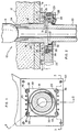
- valve assembly 10 is secured to an exterior portion of a vessel.
- a nozzle 16/18 penetrates a vessel wall 11, which is normally a steel shell, and a vessel lining 12, which is normally a refractory brick.
- a stopper rod 14 engages the upper portion of the nozzle 18 to permit or stop the flow of steel from the interior portion of the vessel to a tube 20.
- the valve assembly 10 is secured to the vessel wall 11 by means of a mounting plate 15, the same securing the tube 20 to a nozzle plate 16.
- the nozzle plate 16 shown to the left-hand portion of the centre line is unitary and thus includes both the nozzle portion and plate portion.
- nozzle/plate Shown diagrammatically at the right-hand side of Figure 2 is a two-piece nozzle 18, with a lower plate 19 interlocked and secured to the nozzle 18.
- a stopper rod there is a risk of leakage at any joint, and accordingly the unitary nozzle plate construction 16 is most desirable.
- the individual nozzle 18 co-operating with the plate 19 may prove more desirable.
- nozzle/plate collectively refers to both embodiments.
- the tube 20 has a tube collar 21 at its upstream portion and is surrounded by a tube collar band 22 normally of a metal material.
- the purpose of the tube collar band is to engage the tube collar 22 and to receive rocker arms 26 and permit the tube to be exchanged or shifted in and out of teeming relationship with the nozzle/plate assembly 16/18/19.
- a stopper rod seat 24 is provided at the upper portion of the nozzle/plate 16 or the nozzle 18. It is curvilinear and seats with the curvilinear bullet nose of the stopper rod 14.
- a main frame 25 is shown in both Figures 1 and 2 and secures the rocker arms 26 which are mounted to rocker pivots 28 and rocker spring 29 so that the central end of the rocker 26 engages the downstream portion of the tube collar band 22.
- a clamp ring 30 as shown in Figures 1, 2 and 3 is substantially rectangular and provided centrally with a clamp ring taper 31 which matingly engages a plate taper 32 of the plate 19 or the lower portion of the plate/nozzle 16.
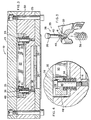
- the clamp spring assembly 35 includes a clamp guide 36 and a clamp spring 38, the clamp spring 38 being secured beneath a guide head 39 and in coaxial relationship to a clamp guide shank 40 above mounting threads 41. This relationship is shown in enlarged scale in Figure 4, and in exploded relationship in Figure 5.
- FIG. 1 it will be seen that there is a rocker spring cooling manifold 45 with a plurality of orifices mounted to cool the rocker springs in operation.
- the clamp ring 30 is provided with clamping ears 46 at one side, and the clamp key 48 at the opposite corners is of a different size to prevent reversal of the clamp ring 30.
- mounting bolts 50 are employed, particularly as shown in Figure 3, to secure the main frame to the mounting plate.
- the method of operating the valve assembly 10 includes mounting such a valve assembly 10 onto a vessel wall 11 and positioning a mounting plate 15 onto the vessel wall 11 and inserting a nozzle/plate 16 or nozzle 18 and plate 19 into the vessel.
- the relationship of the elements and the sequence of assembly is illustrated in Figure 6. Provision is made for a main frame 25 having rockers 26 and including a clamp ring 30 having a central clamp ring taper 31 against the plate taper 32.
- the clamp spring assembly 35 is also provided to bridge the gap between the clamp ring 30 and the main frame 25.
- the steps of the method involve firstly placing the clamping ring 30 in surrounding relationship to the plate 16, 19 by the opposed tapered sidewalls 31, 32. Thereafter, the clamping ring 30 is loaded in engagement with the tapered sidewalls 32 of the plate 16, 19 by means of clampingly engaging the main frame 25 to the mounting plate 15, thereby applying a compressive pre-stress in plate 16, 19.
- the final step in the method contemplates proportioning the spacial relationship between the mounting plate 15, main frame 25, clamping ring 30 and yieldable spring assembly 35 to ensure that the mounting force of the frame 25 is shared between the preloading of the clamp ring 30 to the plate 16, 19 and the subsequent clamping action by the main frame 25 against the clamping ring 30 as the main frame 25 is secured to the mounting plate 15.
Landscapes
- Engineering & Computer Science (AREA)
- Mechanical Engineering (AREA)
- Casting Support Devices, Ladles, And Melt Control Thereby (AREA)
- Nozzles (AREA)
- Lift Valve (AREA)
- Encapsulation Of And Coatings For Semiconductor Or Solid State Devices (AREA)
- Coating Apparatus (AREA)
- Treatment Of Steel In Its Molten State (AREA)
- Furnace Housings, Linings, Walls, And Ceilings (AREA)
- Flanged Joints, Insulating Joints, And Other Joints (AREA)
- Sealing Devices (AREA)
- Moulding By Coating Moulds (AREA)
- Manufacture Of Alloys Or Alloy Compounds (AREA)
Applications Claiming Priority (3)
| Application Number | Priority Date | Filing Date | Title |
|---|---|---|---|
| US591067 | 1990-10-01 | ||
| US07/591,067 US5044533A (en) | 1990-10-01 | 1990-10-01 | Clamp for bandless refractory and method |
| PCT/US1991/007145 WO1992005901A1 (en) | 1990-10-01 | 1991-09-27 | Clamp for bandless refractory and method |
Publications (2)
| Publication Number | Publication Date |
|---|---|
| EP0502185A1 EP0502185A1 (en) | 1992-09-09 |
| EP0502185B1 true EP0502185B1 (en) | 1995-11-02 |
Family
ID=24364922
Family Applications (1)
| Application Number | Title | Priority Date | Filing Date |
|---|---|---|---|
| EP91919361A Expired - Lifetime EP0502185B1 (en) | 1990-10-01 | 1991-09-27 | Valve assembly for nozzle/plate assembly |
Country Status (11)
| Country | Link |
|---|---|
| US (1) | US5044533A (da) |
| EP (1) | EP0502185B1 (da) |
| JP (1) | JP3098253B2 (da) |
| AT (1) | ATE129655T1 (da) |
| BR (1) | BR9105912A (da) |
| CA (1) | CA2050729C (da) |
| DE (1) | DE69114264T2 (da) |
| DK (1) | DK0502185T3 (da) |
| ES (1) | ES2081501T3 (da) |
| MX (1) | MX9101249A (da) |
| WO (1) | WO1992005901A1 (da) |
Cited By (2)
| Publication number | Priority date | Publication date | Assignee | Title |
|---|---|---|---|---|
| US11654480B2 (en) | 2018-06-26 | 2023-05-23 | Refractory Intellectual Property Gmbh & Co. Kg | Sliding closure for a metallurgical vessel, preferably a distributor vessel for a continuous casting facility |
| RU2798379C2 (ru) * | 2018-06-26 | 2023-06-21 | Рефрактори Интеллектуал Проперти ГмбХ энд Ко. КГ | Шиберный затвор для металлургического контейнера, предпочтительно промежуточного ковша для системы непрерывного литья |
Families Citing this family (10)
| Publication number | Priority date | Publication date | Assignee | Title |
|---|---|---|---|---|
| US5348275A (en) * | 1993-07-26 | 1994-09-20 | Magneco/Metrel, Inc. | Tundish nozzle assembly block |
| FR2736289B1 (fr) * | 1995-07-03 | 1997-08-29 | Vesuvius France Sa | Ensemble plaque-busette interne comportant une zone de moindre resistance |
| GB9819191D0 (en) * | 1998-09-04 | 1998-10-28 | Mills Stephen D | Unibore interchangable nozzle system |
| TW553788B (en) * | 2000-04-21 | 2003-09-21 | Vesuvius Crucible Co | One-piece inner nozzle and clamping device for an inner nozzle |
| DE10033904A1 (de) * | 2000-07-12 | 2002-01-31 | Stopinc Ag Huenenberg | Schieberverschluss zum Vergiessen von Metallschmelze, sowie eine dazugehörige feuerfeste Platteneinheit |
| EP1439016A1 (fr) * | 2003-01-20 | 2004-07-21 | Vesuvius Group S.A | Tube de coulée, dispositif de clamage d'un tube de coulée et installation de coulée |
| EP1454687A1 (fr) * | 2003-03-06 | 2004-09-08 | Vesuvius Group S.A | Dispositif de montage d'une busette collectrice |
| JP4669888B2 (ja) * | 2008-01-16 | 2011-04-13 | 品川リフラクトリーズ株式会社 | 浸漬ノズル支持交換機構 |
| EP2386368A1 (fr) | 2010-03-19 | 2011-11-16 | Vesuvius Group S.A | Busette interne pour le transfert de métal liquide contenu dans un récipient, système de clamage de cette busette et dispositif de coulée |
| CN113084144B (zh) * | 2021-03-31 | 2022-07-15 | 湖南镭目科技有限公司 | 一种套管拆装装置 |
Family Cites Families (6)
| Publication number | Priority date | Publication date | Assignee | Title |
|---|---|---|---|---|
| AT171189B (de) * | 1950-01-04 | 1952-05-10 | Nikolaus Wachter | Bodenverschluß für Gießpfannen |
| US2961722A (en) | 1958-10-29 | 1960-11-29 | Skf Svenska Kullagerfab Ab | Casting molten material in a vacuum |
| US3685705A (en) * | 1971-03-24 | 1972-08-22 | James W Cessna | Sliding gate valve having spring biased slide |
| JPH0335481Y2 (da) * | 1984-09-11 | 1991-07-26 | ||
| DE3635717C1 (de) * | 1986-10-21 | 1987-07-16 | Stopinc Ag | Vorrichtung zum Einspannen feuerfester Platten in metallische Rahmen von Schieberverschluessen |
| US4887748A (en) * | 1986-12-29 | 1989-12-19 | J. W. Hicks, Inc. | Apparatus and method for attachment of submerged nozzle to lower plate of sliding gate valve mechanism for a continuous casting operation |
-
1990
- 1990-10-01 US US07/591,067 patent/US5044533A/en not_active Expired - Lifetime
-
1991
- 1991-09-05 CA CA002050729A patent/CA2050729C/en not_active Expired - Fee Related
- 1991-09-25 MX MX9101249A patent/MX9101249A/es unknown
- 1991-09-27 BR BR919105912A patent/BR9105912A/pt not_active IP Right Cessation
- 1991-09-27 DK DK91919361.5T patent/DK0502185T3/da active
- 1991-09-27 ES ES91919361T patent/ES2081501T3/es not_active Expired - Lifetime
- 1991-09-27 JP JP03516805A patent/JP3098253B2/ja not_active Expired - Fee Related
- 1991-09-27 AT AT91919361T patent/ATE129655T1/de not_active IP Right Cessation
- 1991-09-27 EP EP91919361A patent/EP0502185B1/en not_active Expired - Lifetime
- 1991-09-27 WO PCT/US1991/007145 patent/WO1992005901A1/en not_active Ceased
- 1991-09-27 DE DE69114264T patent/DE69114264T2/de not_active Expired - Fee Related
Cited By (2)
| Publication number | Priority date | Publication date | Assignee | Title |
|---|---|---|---|---|
| US11654480B2 (en) | 2018-06-26 | 2023-05-23 | Refractory Intellectual Property Gmbh & Co. Kg | Sliding closure for a metallurgical vessel, preferably a distributor vessel for a continuous casting facility |
| RU2798379C2 (ru) * | 2018-06-26 | 2023-06-21 | Рефрактори Интеллектуал Проперти ГмбХ энд Ко. КГ | Шиберный затвор для металлургического контейнера, предпочтительно промежуточного ковша для системы непрерывного литья |
Also Published As
| Publication number | Publication date |
|---|---|
| US5044533A (en) | 1991-09-03 |
| CA2050729C (en) | 2002-07-23 |
| JPH07501748A (ja) | 1995-02-23 |
| DK0502185T3 (da) | 1995-12-04 |
| DE69114264D1 (de) | 1995-12-07 |
| ATE129655T1 (de) | 1995-11-15 |
| EP0502185A1 (en) | 1992-09-09 |
| ES2081501T3 (es) | 1996-03-16 |
| WO1992005901A1 (en) | 1992-04-16 |
| JP3098253B2 (ja) | 2000-10-16 |
| CA2050729A1 (en) | 1992-04-02 |
| BR9105912A (pt) | 1992-11-03 |
| MX9101249A (es) | 1992-06-05 |
| DE69114264T2 (de) | 1996-05-02 |
Similar Documents
| Publication | Publication Date | Title |
|---|---|---|
| EP0502185B1 (en) | Valve assembly for nozzle/plate assembly | |
| EP0416719B1 (en) | Shearing gate valve | |
| US4114851A (en) | High pressure valve | |
| DE60115223T2 (de) | Verbessertes heisskanal-verschlussventil kolbenaggregat | |
| US3215399A (en) | Double disc construction for gate valves | |
| CA1339524C (en) | Refractory valve plate for sliding gate valves | |
| US4548386A (en) | Gate valve | |
| DE3369868D1 (en) | Method for forming a valve seat on an endothermic engine cylinder head, and the engine with valve seats formed by this method | |
| US4561573A (en) | Valve and replaceable collector nozzle | |
| US20040129915A1 (en) | Seat ring for valves | |
| JPS59219106A (ja) | チヤツク用圧力媒体供給装置 | |
| EP0069491A1 (en) | Bearing retainers for a rotary valve | |
| US4887748A (en) | Apparatus and method for attachment of submerged nozzle to lower plate of sliding gate valve mechanism for a continuous casting operation | |
| DE3233392A1 (de) | Tellerventil fuer ein gaswechselventil | |
| DE3486039T2 (de) | Flachschieber und verfahren zur betaetigung. | |
| EP0559886A1 (en) | PLATE CHANGER, PLATE AND METHOD FOR CHANGING THE SAME. | |
| ES8606507A1 (es) | Metodo para tratar termicamente con solucion valvulas accio-nadas por levas | |
| US6341761B1 (en) | Seated valve | |
| US4999911A (en) | Method of manufacturing an automobile valve for use in rebuilding engines | |
| US4603842A (en) | Method of sliding gate valve operation | |
| CA1187142A (en) | Method for inductively heating valve seat inserts | |
| JPH06507695A (ja) | 遮断弁 | |
| DE3527659C2 (da) | ||
| DE4411050A1 (de) | Kugelhahn | |
| JPS5997750A (ja) | 金型用ピン |
Legal Events
| Date | Code | Title | Description |
|---|---|---|---|
| PUAI | Public reference made under article 153(3) epc to a published international application that has entered the european phase |
Free format text: ORIGINAL CODE: 0009012 |
|
| AK | Designated contracting states |
Kind code of ref document: A1 Designated state(s): AT BE CH DE DK ES FR GB GR IT LI LU NL SE |
|
| 17P | Request for examination filed |
Effective date: 19921007 |
|
| 17Q | First examination report despatched |
Effective date: 19940120 |
|
| GRAA | (expected) grant |
Free format text: ORIGINAL CODE: 0009210 |
|
| AK | Designated contracting states |
Kind code of ref document: B1 Designated state(s): AT BE CH DE DK ES FR GB GR IT LI LU NL SE |
|
| PG25 | Lapsed in a contracting state [announced via postgrant information from national office to epo] |
Ref country code: LI Effective date: 19951102 Ref country code: GR Free format text: LAPSE BECAUSE OF FAILURE TO SUBMIT A TRANSLATION OF THE DESCRIPTION OR TO PAY THE FEE WITHIN THE PRESCRIBED TIME-LIMIT Effective date: 19951102 Ref country code: CH Effective date: 19951102 |
|
| REF | Corresponds to: |
Ref document number: 129655 Country of ref document: AT Date of ref document: 19951115 Kind code of ref document: T |
|
| ITF | It: translation for a ep patent filed | ||
| REG | Reference to a national code |
Ref country code: DK Ref legal event code: T3 |
|
| REF | Corresponds to: |
Ref document number: 69114264 Country of ref document: DE Date of ref document: 19951207 |
|
| ET | Fr: translation filed | ||
| REG | Reference to a national code |
Ref country code: ES Ref legal event code: FG2A Ref document number: 2081501 Country of ref document: ES Kind code of ref document: T3 |
|
| REG | Reference to a national code |
Ref country code: CH Ref legal event code: PL |
|
| PLBE | No opposition filed within time limit |
Free format text: ORIGINAL CODE: 0009261 |
|
| STAA | Information on the status of an ep patent application or granted ep patent |
Free format text: STATUS: NO OPPOSITION FILED WITHIN TIME LIMIT |
|
| 26N | No opposition filed | ||
| REG | Reference to a national code |
Ref country code: GB Ref legal event code: IF02 |
|
| PGFP | Annual fee paid to national office [announced via postgrant information from national office to epo] |
Ref country code: DK Payment date: 20020902 Year of fee payment: 12 |
|
| PGFP | Annual fee paid to national office [announced via postgrant information from national office to epo] |
Ref country code: LU Payment date: 20020919 Year of fee payment: 12 |
|
| PGFP | Annual fee paid to national office [announced via postgrant information from national office to epo] |
Ref country code: AT Payment date: 20030902 Year of fee payment: 13 |
|
| PGFP | Annual fee paid to national office [announced via postgrant information from national office to epo] |
Ref country code: NL Payment date: 20030909 Year of fee payment: 13 |
|
| PGFP | Annual fee paid to national office [announced via postgrant information from national office to epo] |
Ref country code: FR Payment date: 20030918 Year of fee payment: 13 |
|
| PGFP | Annual fee paid to national office [announced via postgrant information from national office to epo] |
Ref country code: SE Payment date: 20030919 Year of fee payment: 13 |
|
| PGFP | Annual fee paid to national office [announced via postgrant information from national office to epo] |
Ref country code: GB Payment date: 20030924 Year of fee payment: 13 |
|
| PG25 | Lapsed in a contracting state [announced via postgrant information from national office to epo] |
Ref country code: LU Free format text: LAPSE BECAUSE OF NON-PAYMENT OF DUE FEES Effective date: 20030927 |
|
| PG25 | Lapsed in a contracting state [announced via postgrant information from national office to epo] |
Ref country code: DK Free format text: LAPSE BECAUSE OF NON-PAYMENT OF DUE FEES Effective date: 20030930 |
|
| PGFP | Annual fee paid to national office [announced via postgrant information from national office to epo] |
Ref country code: ES Payment date: 20031008 Year of fee payment: 13 |
|
| PGFP | Annual fee paid to national office [announced via postgrant information from national office to epo] |
Ref country code: BE Payment date: 20031016 Year of fee payment: 13 |
|
| PGFP | Annual fee paid to national office [announced via postgrant information from national office to epo] |
Ref country code: DE Payment date: 20031031 Year of fee payment: 13 |
|
| REG | Reference to a national code |
Ref country code: DK Ref legal event code: EBP |
|
| PG25 | Lapsed in a contracting state [announced via postgrant information from national office to epo] |
Ref country code: GB Free format text: LAPSE BECAUSE OF NON-PAYMENT OF DUE FEES Effective date: 20040927 Ref country code: AT Free format text: LAPSE BECAUSE OF NON-PAYMENT OF DUE FEES Effective date: 20040927 |
|
| PG25 | Lapsed in a contracting state [announced via postgrant information from national office to epo] |
Ref country code: SE Free format text: LAPSE BECAUSE OF NON-PAYMENT OF DUE FEES Effective date: 20040928 Ref country code: ES Free format text: LAPSE BECAUSE OF NON-PAYMENT OF DUE FEES Effective date: 20040928 |
|
| PG25 | Lapsed in a contracting state [announced via postgrant information from national office to epo] |
Ref country code: BE Free format text: LAPSE BECAUSE OF NON-PAYMENT OF DUE FEES Effective date: 20040930 |
|
| BERE | Be: lapsed |
Owner name: *KING PATRICK D. Effective date: 20040930 Owner name: *FLO-CON SYSTEMS INC. Effective date: 20040930 |
|
| PG25 | Lapsed in a contracting state [announced via postgrant information from national office to epo] |
Ref country code: NL Free format text: LAPSE BECAUSE OF NON-PAYMENT OF DUE FEES Effective date: 20050401 Ref country code: DE Free format text: LAPSE BECAUSE OF NON-PAYMENT OF DUE FEES Effective date: 20050401 |
|
| EUG | Se: european patent has lapsed | ||
| GBPC | Gb: european patent ceased through non-payment of renewal fee |
Effective date: 20040927 |
|
| PG25 | Lapsed in a contracting state [announced via postgrant information from national office to epo] |
Ref country code: FR Free format text: LAPSE BECAUSE OF NON-PAYMENT OF DUE FEES Effective date: 20050531 |
|
| NLV4 | Nl: lapsed or anulled due to non-payment of the annual fee |
Effective date: 20050401 |
|
| REG | Reference to a national code |
Ref country code: FR Ref legal event code: ST |
|
| PG25 | Lapsed in a contracting state [announced via postgrant information from national office to epo] |
Ref country code: IT Free format text: LAPSE BECAUSE OF NON-PAYMENT OF DUE FEES;WARNING: LAPSES OF ITALIAN PATENTS WITH EFFECTIVE DATE BEFORE 2007 MAY HAVE OCCURRED AT ANY TIME BEFORE 2007. THE CORRECT EFFECTIVE DATE MAY BE DIFFERENT FROM THE ONE RECORDED. Effective date: 20050927 |
|
| REG | Reference to a national code |
Ref country code: ES Ref legal event code: FD2A Effective date: 20040928 |
|
| BERE | Be: lapsed |
Owner name: *KING PATRICK D. Effective date: 20040930 Owner name: *FLO-CON SYSTEMS INC. Effective date: 20040930 |