EP0501012B1 - Pompe de drainage - Google Patents
Pompe de drainage Download PDFInfo
- Publication number
- EP0501012B1 EP0501012B1 EP91117584A EP91117584A EP0501012B1 EP 0501012 B1 EP0501012 B1 EP 0501012B1 EP 91117584 A EP91117584 A EP 91117584A EP 91117584 A EP91117584 A EP 91117584A EP 0501012 B1 EP0501012 B1 EP 0501012B1
- Authority
- EP
- European Patent Office
- Prior art keywords
- suction
- water level
- pump
- air
- intake pipe
- Prior art date
- Legal status (The legal status is an assumption and is not a legal conclusion. Google has not performed a legal analysis and makes no representation as to the accuracy of the status listed.)
- Expired - Lifetime
Links
Images


Classifications
-
- F—MECHANICAL ENGINEERING; LIGHTING; HEATING; WEAPONS; BLASTING
- F04—POSITIVE - DISPLACEMENT MACHINES FOR LIQUIDS; PUMPS FOR LIQUIDS OR ELASTIC FLUIDS
- F04D—NON-POSITIVE-DISPLACEMENT PUMPS
- F04D15/00—Control, e.g. regulation, of pumps, pumping installations or systems
- F04D15/0027—Varying behaviour or the very pump
- F04D15/0044—Varying behaviour or the very pump by introducing a gas
Definitions
- This invention relates to a drainage pump, and more particularly a vertical shaft pump of all-level all-speed operation type which is operated at a constant speed irrespective of the suction water level.
- FIG. 8 is a sectional view of a conventional vertical shaft type axial flow pump.
- FIG. 9 is a front view of another conventional vertical shaft type axial flow pump.
- a suction tube d is longer than usual
- an impeller e is mounted above the water level L.W.L corresponding to the limit suction water level
- a draining pipe f is installed immediately under the impeller e and connected to an air-water switching means g at the upper end.
- the pump is operated steadily at a speed of 100%. If the suction water level becomes lower than the water level L.W.L, air is fed to a position immediately under the impeller e from the air-water switching means to perform the air-water separation because air suction vortexes b easily occur. Then, the pump is operated still at a speed of 100% under the condition of zero discharge, while the air and water are stirred.
- the conventional vertical shaft pump requires a control system for speed reduction, or requires a draining pipe f and an air-water switching means g .
- the limit water depth h at which the pump does not suck air from the water surface on the suction side is about 1.2 times as large as the bore of the suction port 3.
- it is necessary to restrict the pump discharge by controlling the rotational speed of the vertical shaft pump or the degree of opening of the discharge valve.
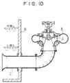
- FIG 10 is a view for explaining the construction of a conventional dry pit type pump.
- this pump is installed outside an intake chamber a .
- the pump sucks water in the intake chamber a through a suction tube i passing through the side wall of intake chamber a, pressurizes the water with an impeller j , and discharges it through the scroll chamber k .
- H.W.L denotes the highest level of water flowing into the intake chamber a
- L.W.L denotes the lowest water level at which the pump can operate safely without the occurrence of air suction vortexes or submerged vortexes.
- An object of the present invention is to provide a drainage pump which can operate stably even when the suction water level is lower than a specified level.
- the drainage pump of this invention comprises an air intake pipe having one end opening near an impeller in a suction tube and the other end opening at a preset lowest suction water level, characterized in that a hole passing through said suction tube and communicating the throat portion of the suction tube to the atmosphere is formed near the impeller.
- Another drainage pump of this invention comprises a first branch pipe which is connected horizontally to the middle part of the suction tube and which rises vertically, a second branch pipe which communicates with this first branch pipe and branches horizontally at one end so as to be in communication with the impeller suction portion at one end and connects at the other end to the air intake pipe extending vertically and having its open end at a position higher than the highest suction water level, and a main valve disposed between the first and second branch pipes.
- the impeller suction portion is indirectly connected to the position corresponding to the suction water level requiring air suction, even a dry pit type pump can be operated in such a manner so as to make the best of the advantages of a wet pit type pump and preclude the entrance of foreign matters.
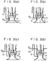
- FIGS 1 through 3 show a vertical shaft type axial flow pump according to this invention.
- the embodiment of the pump shown in these figures are used for drainage of rain water.
- a pump 10 has three small holes 14 having a size equivalent to 0.5-3.0% of the area of a throat portion 13 near the entrance of an impeller 12 in a suction tube (cover) 11.
- an air intake pipe 15 which has an opening at a base end 15a to the throat portion 13 at substantially the same level with the small holes 14 in the suction tube 11.
- the air intake pipe 15 has a size equivalent to 0.5-3.0% of the area of the throat portion 13.
- the end 15b of the air intake pipe 15 opens to the water level L.W.L at which air suction vortexes are not generated from the water surface W.L on the suction side when the pump is operated at a specified discharge rate of flow.
- the air intake pipe rises from the water level and is bent down in an inverse U shape.
- the number of the small holes 14 and the number of the air intake pipes 15 may be single or plural.
- Reference numeral 16 denotes a main shaft, and 17 a guide vane.
- the vertical shaft pump of this invention can operate stably all the time under the normal condition without the air-water stirring at the impeller 12 or the generation of air suction vortexes at the water surface on the suction side irrespective of how far the suction water level W.L lowers. Therefore, the pump of this type is suitable as a pump which must operate without decreasing its rotational speed even when the water level is below the impeller 12, such as pumps for draining rain water.
- the pump of this invention requires no special operation or tools, such as the rotational speed control of the pump and the control of the opening degree of a discharge valve in response to changes in suction water level, and provides nearly the same service life and reliability as those of the conventional pump of this type even if it is used under harsh conditions.
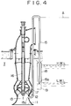
- Figure 4 shows an improvement of the above embodiment of the pump.
- an air intake pipe 6 rises to a high position A where liquid does not flow in the pipe, and then is bent downward from the top, its end 15b opening to the set low water level L.W.L of the intake chamber T.
- a cylinder 18 with its both ends open is coaxially disposed with a gap for permitting air to flow between the air intake pipe 15 and the cylinder 18.
- a strainer which can suck liquid is mounted.
- the upper end of the cylinder 18 opens to a position higher than the highest water level H.W.L at which the pump can suck water.
- the rain water or sewage flowing through a suction tube 11 passes through a throat portion 13, is pressurized by the impeller 12, and is discharged through a guide vane 17. Since the end 15b of the air intake pipe 15 opens at the position of the low water level L.W.L at which air suction is necessary, air suction is performed only when the water level is lower than the L.W.L. In this case, the strainer 19 mounted at the position of end 15b prevents foreign matters on the water surface from entering the air intake pipe 15. Although the strainer 19 sometimes has a high resistance due to foreign matters, air can be sucked from the upper opening of the cylinder 18 in this case; therefore, shortage of suction air does not occur.
- the water in the intake chamber T When the water level is higher than the L.W.L, the water in the intake chamber T is sucked into the air intake pipe 15 through the opening of the strainer 19. In this case, air is not sucked into, and no effect of air entrance is observed. Therefore, prescribed pumping is carried out through the suction tube 11, and the specified pumping performance can be achieved. Since the air intake pipe rises up to a high position A where liquid does not flow in the pipe, the amount of water flow from the strainer 19 is very small, which prevents the strainer 19 from clogging due to the suction of liquid. Even if the strainer 19 clogs to some degree, the performance is not impaired. For these reasons, even if foreign matters enter the water flowing into the suction chamber T, the function of air intake pipe 15 is not impaired, and sound pump operation becomes possible at any water level.
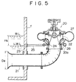
- FIG. 5 is a sectional view of another embodiment of this invention for explaining the construction of a dry pit type pump.
- Figure 6 is a graph for explaining the operation of the pump.
- the dry pit type pump of this invention is a volute pump used for moving sewage water.
- the pump 20 is installed outside the intake chamber T. This pump sucks sewage in the intake chamber T through a suction tube 21 passing through the side wall of intake chamber T.
- the sewage is pressurized by an impeller 22 and discharged through a scroll chamber 27.
- W.L denotes the water level of sewage flowing into the intake chamber T, namely the suction water level of the pump 20, and L.W.L denotes the lowest water level at which the pump can be operated without producing air suction vortexes and submerged vortexes.
- L.W.L denotes the lowest water level at which the pump can be operated without producing air suction vortexes and submerged vortexes.
- a plurality of air suction holes 24 are drilled in the radial direction, which are connected to each other by a ring tube 28.
- the side wall of intake chamber T has a through hole drilled at a height corresponding to the lowest suction water level L.W.L, which is in communication with the ring tube 28 through an air intake pipe.
- the pump may be a mixed flow pump or a pump of other type.
- the pressure at the air suction holes 24 immediately under the impeller 22 is determined by the water level W.L and the pressure loss at the suction tube 21.
- the pump discharge Q W determines the level difference H s in which the static pressure H i is negative in relation to the atmospheric pressure H b . Therefore, if the pump discharge QW is large, the static pressure H i at the air suction hole 24 is negative even when the water level is considerably high.
- ⁇ is the pump efficiency
- ⁇ n and Q n are the efficiency and the pump discharge, respectively, in the case where the water level is sufficiently high
- D b is the bellmouth diameter of the suction tube 21.
- the through hole 29 in the side wall of intake chamber T is installed at the height corresponding to the lowest suction water level L.W.L, and this through hole connects to the air suction holes 24 installed in the suction casing immediately under the entrance of impeller 22 through the air intake pipe 25. Since the opening of the air intake pipe 25, namely the through hole 29, is in the water when the water level is high though the static pressure H i at the air suction holes is negative even when the water level is considerably high, the sewage in the intake chamber T flows into the air intake pipe 25, but the performance of the pump is not deteriorated. When the water level W.L is below the lowest suction water level L.W.L, air suction is performed through the air suction pipe 25, so that the pump discharge Q W suddenly decreases.
- the pump can operate safely without reducing its rotational speed because there is no risk of producing air suction vortexes and submerged vortexes.
- the pump discharge Q a is about 10-20% of a specified rate of flow of the pump
- the pumped water at the suction casing immediately under the entrance of the impeller 22 separates into two phases of air and liquid, which makes the pumping operation impossible.
- the pump performs a quiet holding operation.
- the pump starts pumping operation.
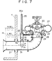
- FIG. 7 shows an improvement of the above-described volute type mixed flow pump.
- a first branch pipe 31 is connected in the horizontal direction midway in the suction tube 21 protruding into the intake chamber T.
- This first branch pipe 31 is raised vertically and connected to a main valve 32.
- the main valve 32 is connected to a second branch pipe 33.
- the branch point of the second branch pipe 33 lies at the position of the water level L.W.L requiring air suction.
- a small-diameter branch pipe 34 extends horizontally so as to connect to the ring tube 28 which is in communication with the air suction holes 24 of the suction casing.
- the second branch pipe 33 is connected to an air intake pipe 35 extending vertically.
- the end 35a of the air intake pipe 35 opens at a position higher than the highest suction water level H.W.L.
- the main flow at the suction casing is made by the pressure difference (P 1 - P 3 ) between the pressure P 1 at the first branch point and the pressure P 3 at the suction casing, the velocity of the main flow being V 3 .
- water also flows by the pressure difference (P 2 - P 3 ) between the pressure P 2 at the second branch point and the pressure P 3 at the suction casing. Since the loss factor including the air suction holes 24 of the small-diameter branch pipe 34 is higher than the loss factor ⁇ of the main flow, the amount of water flowing in the branch pipe 34 is small.
- the first branch pipe branches in the horizontal direction, and water flows by the pressure difference (P 1 - P 2 ) between the pressure P 1 at the first branch point and the pressure P 2 at the second branch point with a low flow velocity of V 2 . Therefore, it is difficult for foreign matters to enter the first branch pipe 31. Even if it enters, sludge and the like will settle at the position where the pipe rises vertically because the velocity V 2 is low. If the pipe is clogged by foreign matters, maintenance work can be easily carried out by closing the main valve.
- Air is sucked when the pressure P 2 becomes a negative pressure.
- the condition of air suction is expressed as follows: (H - H 2 ) ⁇ ( ⁇ 1 *V 1 2 /2g + ⁇ 2 *V 2 2 /2g)
- H 2 H - ⁇ 1 /2g(Q/A 1 ) 2
- a 1 is the sectional area of the suction tube 21.
Landscapes
- Engineering & Computer Science (AREA)
- Mechanical Engineering (AREA)
- General Engineering & Computer Science (AREA)
- Structures Of Non-Positive Displacement Pumps (AREA)
- Control Of Non-Positive-Displacement Pumps (AREA)
Claims (6)
- Pompe de drainage de type à arbre vertical comprenant un tuyau d'admission d'air (15) ayant une extrémité (15a) ouverte près d'une hélice (12) dans un tube d'aspiration (11) et une autre extrémité (15b) ouverte à un niveau d'eau d'aspiration minimal prédéfini, caractérisée en ce qu'un trou (14) passant à travers ledit tube d'aspiration (11) et mettant la partie de gorge (13) du tube d'aspiration (11) en communication avec l'atmosphère est formé près de l'hélice (12).
- Pompe à flux axial de type à arbre vertical selon la revendication 1, caractérisée en ce qu'un cylindre (18) dont les deux extrémités sont ouvertes est disposé coaxialement à ladite autre extrémité (15b) du tuyau d'admission d'air (15) avec un espace permettant à l'air de circuler entre ledit tuyau d'admission d'air (15) et ledit cylindre (18), un crible (19) étant installé à l'extrémité inférieure dudit cylindre (18), et l'extrémité supérieure dudit cylindre s'ouvrant en un point situé plus haut que le niveau d'eau d'aspiration le plus élevé.
- Pompe de drainage pour puits sec selon la revendication 1, caractérisée en ce que l'autre extrémité dudit tuyau d'admission d'air (21) est montée de telle sorte que ledit tuyau d'admission d'air traverse une paroi latérale d'une chambre d'admission (T).
- Pompe de drainage selon la revendication 3, caractérisée en ce que ladite pompe de drainage pour puits sec est une pompe à volute (20).
- Pompe de drainage de type à arbre vertical selon la revendication 1, caractérisée en outre en ce qu'elle comporte un premier tube de branchement (31) qui est raccordé horizontalement à une section médiane du tube d'aspiration (21) et qui monte verticalement ; un second tube de branchement (33) raccordé audit premier tube de branchement (31) et au tuyau d'admission (34, 15) par ladite autre ouverture (15b) au niveau d'eau d'aspiration minimal prédéfini et qui est raccordé à l'autre extrémité à une prise d'air (35) orientée verticalement et pourvue d'une ouverture d'extrémité (35a) en un point plus élevé que le niveau d'eau d'aspiration le plus élevé ; et une soupape principale (32) est montée entre lesdits premier (31) et second tubes de branchement (33).
- Pompe de drainage selon la revendication 5, caractérisée en ce que ladite pompe de drainage de type à arbre vertical est une pompe hélico-centrifuge à volute.
Applications Claiming Priority (4)
| Application Number | Priority Date | Filing Date | Title |
|---|---|---|---|
| JP5347491A JP2915600B2 (ja) | 1991-02-25 | 1991-02-25 | 渦巻斜流ポンプ |
| JP53474/91 | 1991-02-25 | ||
| JP3164691U JP2515351Y2 (ja) | 1991-04-09 | 1991-04-09 | 立軸ポンプ |
| JP31646/91U | 1991-04-09 |
Publications (2)
| Publication Number | Publication Date |
|---|---|
| EP0501012A1 EP0501012A1 (fr) | 1992-09-02 |
| EP0501012B1 true EP0501012B1 (fr) | 1997-03-05 |
Family
ID=26370151
Family Applications (1)
| Application Number | Title | Priority Date | Filing Date |
|---|---|---|---|
| EP91117584A Expired - Lifetime EP0501012B1 (fr) | 1991-02-25 | 1991-10-15 | Pompe de drainage |
Country Status (2)
| Country | Link |
|---|---|
| US (1) | US5252025A (fr) |
| EP (1) | EP0501012B1 (fr) |
Families Citing this family (6)
| Publication number | Priority date | Publication date | Assignee | Title |
|---|---|---|---|---|
| US5860790A (en) * | 1996-10-10 | 1999-01-19 | Wang; Hsiang-Yun | Automatic draining arrangement without position limitation |
| US6322333B1 (en) | 1997-12-05 | 2001-11-27 | Roy Knight | Device for enhancing fluid flow |
| US5841510A (en) * | 1998-02-11 | 1998-11-24 | Roggy; David L. | Rotatable diagnostic lens for evaluation of the irido-corneal angle, retina and other portions of the eye |
| US6440227B1 (en) | 2000-07-28 | 2002-08-27 | Shop-Vac Corporation | Nozzle and method providing increased liquid lift height for a wet/dry vacuum cleaner |
| US20090086064A1 (en) * | 2007-09-27 | 2009-04-02 | Micron Technology, Inc. | Dynamic adaptive color filter array |
| CN109906994B (zh) * | 2019-04-15 | 2024-04-30 | 郑州市水产技术推广站 | 一种新型生态湿地循环水综合种养系统 |
Family Cites Families (7)
| Publication number | Priority date | Publication date | Assignee | Title |
|---|---|---|---|---|
| US1047134A (en) * | 1912-06-28 | 1912-12-10 | Fritz Oesterlen | Hydraulic turbine. |
| US1474086A (en) * | 1922-04-04 | 1923-11-13 | Poebing Oskar | Regulating water-power stations |
| US2262191A (en) * | 1940-06-26 | 1941-11-11 | Lewis F Moody | Pump |
| CH417344A (de) * | 1964-05-25 | 1966-07-15 | Sulzer Ag | Pumpenanlage |
| CH454628A (de) * | 1966-03-24 | 1968-04-15 | Sulzer Ag | Verfahren zum Inbetriebsetzen einer Pumpe oder Pumpenturbine radialer Bauart in einem Speicherkraftwerk |
| JPS59211771A (ja) * | 1983-05-17 | 1984-11-30 | Toshiba Corp | 水車の水面押下装置 |
| JPH073240B2 (ja) * | 1989-10-31 | 1995-01-18 | 株式会社クボタ | 立軸ポンプ |
-
1991
- 1991-10-15 EP EP91117584A patent/EP0501012B1/fr not_active Expired - Lifetime
- 1991-10-17 US US07/776,779 patent/US5252025A/en not_active Expired - Lifetime
Non-Patent Citations (1)
| Title |
|---|
| PATENT ABSTRACTS OF JAPAN vol. 12, no. 384 (M-753)(3231) 13 October 1988 & JP-A-63 134 897 (KUBOTA) 7 June 1988 * |
Also Published As
| Publication number | Publication date |
|---|---|
| US5252025A (en) | 1993-10-12 |
| EP0501012A1 (fr) | 1992-09-02 |
Similar Documents
| Publication | Publication Date | Title |
|---|---|---|
| US6216788B1 (en) | Sand protection system for electrical submersible pump | |
| EP0501012B1 (fr) | Pompe de drainage | |
| KR940007761B1 (ko) | 수직축 펌프 | |
| JP4463484B2 (ja) | 立軸ポンプ | |
| US5074746A (en) | Constant speed vertical pump with aeration | |
| US20030165380A1 (en) | Self-priming pump | |
| CN209414280U (zh) | 一种深井防堵塞电气控制排水系统 | |
| JP3191104B2 (ja) | 立軸ポンプ | |
| JP3191102B2 (ja) | 立軸ポンプ | |
| PL204069B1 (pl) | Stacja pomp | |
| US3558018A (en) | Water pockets, namely reservoirs for storing water received from underground water pumping equipment | |
| JPS63189688A (ja) | 複数立軸ポンプ運転設備 | |
| JP4422438B2 (ja) | 立軸ポンプ | |
| JP2836659B2 (ja) | サイホン形ポンプ | |
| JPS6129996Y2 (fr) | ||
| JPH0278791A (ja) | ポンプ機場 | |
| JP2560651Y2 (ja) | 立軸形ポンプ | |
| JP3532348B2 (ja) | 高揚程ポンプを具備する揚水装置 | |
| US6561754B1 (en) | Inlet structure for pump installations | |
| JP2512778Y2 (ja) | 全速待機運転ポンプ | |
| JPH11323884A (ja) | 排水ポンプシステム | |
| JP3104786B2 (ja) | 先行待機型ポンプ | |
| JPS6032997A (ja) | 嗚水運転用立軸形ポンプ | |
| SU1023147A2 (ru) | Вакуум-эрлифтна установка | |
| JPH07252876A (ja) | 水中ポンプ装置 |
Legal Events
| Date | Code | Title | Description |
|---|---|---|---|
| PUAI | Public reference made under article 153(3) epc to a published international application that has entered the european phase |
Free format text: ORIGINAL CODE: 0009012 |
|
| AK | Designated contracting states |
Kind code of ref document: A1 Designated state(s): CH FR GB LI NL |
|
| 17P | Request for examination filed |
Effective date: 19921019 |
|
| 17Q | First examination report despatched |
Effective date: 19931112 |
|
| GRAG | Despatch of communication of intention to grant |
Free format text: ORIGINAL CODE: EPIDOS AGRA |
|
| GRAH | Despatch of communication of intention to grant a patent |
Free format text: ORIGINAL CODE: EPIDOS IGRA |
|
| GRAH | Despatch of communication of intention to grant a patent |
Free format text: ORIGINAL CODE: EPIDOS IGRA |
|
| GRAA | (expected) grant |
Free format text: ORIGINAL CODE: 0009210 |
|
| AK | Designated contracting states |
Kind code of ref document: B1 Designated state(s): CH FR GB LI NL |
|
| REG | Reference to a national code |
Ref country code: CH Ref legal event code: NV Representative=s name: ARNOLD & SIEDSMA AG Ref country code: CH Ref legal event code: EP |
|
| ET | Fr: translation filed | ||
| PGFP | Annual fee paid to national office [announced via postgrant information from national office to epo] |
Ref country code: GB Payment date: 19971024 Year of fee payment: 7 |
|
| PGFP | Annual fee paid to national office [announced via postgrant information from national office to epo] |
Ref country code: FR Payment date: 19971030 Year of fee payment: 7 |
|
| PGFP | Annual fee paid to national office [announced via postgrant information from national office to epo] |
Ref country code: NL Payment date: 19971031 Year of fee payment: 7 |
|
| PGFP | Annual fee paid to national office [announced via postgrant information from national office to epo] |
Ref country code: CH Payment date: 19971229 Year of fee payment: 7 |
|
| PLBE | No opposition filed within time limit |
Free format text: ORIGINAL CODE: 0009261 |
|
| STAA | Information on the status of an ep patent application or granted ep patent |
Free format text: STATUS: NO OPPOSITION FILED WITHIN TIME LIMIT |
|
| 26N | No opposition filed | ||
| PG25 | Lapsed in a contracting state [announced via postgrant information from national office to epo] |
Ref country code: GB Free format text: LAPSE BECAUSE OF NON-PAYMENT OF DUE FEES Effective date: 19981015 |
|
| PG25 | Lapsed in a contracting state [announced via postgrant information from national office to epo] |
Ref country code: LI Free format text: LAPSE BECAUSE OF NON-PAYMENT OF DUE FEES Effective date: 19981031 Ref country code: CH Free format text: LAPSE BECAUSE OF NON-PAYMENT OF DUE FEES Effective date: 19981031 |
|
| PG25 | Lapsed in a contracting state [announced via postgrant information from national office to epo] |
Ref country code: NL Free format text: LAPSE BECAUSE OF NON-PAYMENT OF DUE FEES Effective date: 19990501 |
|
| GBPC | Gb: european patent ceased through non-payment of renewal fee |
Effective date: 19981015 |
|
| REG | Reference to a national code |
Ref country code: CH Ref legal event code: PL |
|
| PG25 | Lapsed in a contracting state [announced via postgrant information from national office to epo] |
Ref country code: FR Free format text: LAPSE BECAUSE OF NON-PAYMENT OF DUE FEES Effective date: 19990630 |
|
| NLV4 | Nl: lapsed or anulled due to non-payment of the annual fee |
Effective date: 19990501 |
|
| REG | Reference to a national code |
Ref country code: FR Ref legal event code: ST |