EP0500425B1 - Bloc de connextion électrique enfichable et connecteur incorporant un tel bloc - Google Patents
Bloc de connextion électrique enfichable et connecteur incorporant un tel bloc Download PDFInfo
- Publication number
- EP0500425B1 EP0500425B1 EP92400388A EP92400388A EP0500425B1 EP 0500425 B1 EP0500425 B1 EP 0500425B1 EP 92400388 A EP92400388 A EP 92400388A EP 92400388 A EP92400388 A EP 92400388A EP 0500425 B1 EP0500425 B1 EP 0500425B1
- Authority
- EP
- European Patent Office
- Prior art keywords
- slab
- housing
- terminals
- detents
- abutment
- Prior art date
- Legal status (The legal status is an assumption and is not a legal conclusion. Google has not performed a legal analysis and makes no representation as to the accuracy of the status listed.)
- Expired - Lifetime
Links
- 210000002105 tongue Anatomy 0.000 claims description 5
- 238000005452 bending Methods 0.000 claims description 4
- 239000011810 insulating material Substances 0.000 claims description 2
- 230000000670 limiting effect Effects 0.000 claims description 2
- 238000005192 partition Methods 0.000 claims description 2
- 235000012431 wafers Nutrition 0.000 description 54
- 235000012771 pancakes Nutrition 0.000 description 8
- 230000037431 insertion Effects 0.000 description 7
- 238000003780 insertion Methods 0.000 description 7
- 208000029152 Small face Diseases 0.000 description 4
- 230000000717 retained effect Effects 0.000 description 3
- 230000000295 complement effect Effects 0.000 description 2
- 238000006073 displacement reaction Methods 0.000 description 2
- 238000001514 detection method Methods 0.000 description 1
- 239000000945 filler Substances 0.000 description 1
- 230000014759 maintenance of location Effects 0.000 description 1
- 230000036961 partial effect Effects 0.000 description 1
- 230000001681 protective effect Effects 0.000 description 1
- 230000002441 reversible effect Effects 0.000 description 1
- 229920002994 synthetic fiber Polymers 0.000 description 1
Images

Classifications
-
- H—ELECTRICITY
- H01—ELECTRIC ELEMENTS
- H01R—ELECTRICALLY-CONDUCTIVE CONNECTIONS; STRUCTURAL ASSOCIATIONS OF A PLURALITY OF MUTUALLY-INSULATED ELECTRICAL CONNECTING ELEMENTS; COUPLING DEVICES; CURRENT COLLECTORS
- H01R13/00—Details of coupling devices of the kinds covered by groups H01R12/70 or H01R24/00 - H01R33/00
- H01R13/64—Means for preventing incorrect coupling
-
- H—ELECTRICITY
- H01—ELECTRIC ELEMENTS
- H01R—ELECTRICALLY-CONDUCTIVE CONNECTIONS; STRUCTURAL ASSOCIATIONS OF A PLURALITY OF MUTUALLY-INSULATED ELECTRICAL CONNECTING ELEMENTS; COUPLING DEVICES; CURRENT COLLECTORS
- H01R13/00—Details of coupling devices of the kinds covered by groups H01R12/70 or H01R24/00 - H01R33/00
- H01R13/46—Bases; Cases
- H01R13/514—Bases; Cases composed as a modular blocks or assembly, i.e. composed of co-operating parts provided with contact members or holding contact members between them
Definitions
- the invention relates to electrical connectors with two plug-in connection blocks, and more particularly relates to a connection block for such a connector, of the so-called modular type, comprising a rectangular box whose two opposite faces have longitudinal projections delimiting parallel corridors and flat wafers of insulating material, each wafer occupying one of said corridors, comprising a single row of parallel passages for receiving contact terminals and having a large face cut out in a front part to constitute pawls of individual retention of the terminals by snap-fastening in the terminal holes, the housing and each wafer comprising cooperating coding means authorizing the complete introduction of a wafer only in one orientation.
- a block of the kind defined above can easily be designed to incorporate wafers giving the terminals a pitch of distribution of the contacts variable from one wafer to another (but obviously equal for the cooperating wafers of the two blocks of the same connector ). It is also possible to omit some of the wafers in applications where the corresponding terminals are not necessary. All these features make such a connector particularly advantageous in many fields, such as the automobile and workshops with electronically controlled machine tools and / or robots.
- the invention aims in particular to eliminate this risk.
- it offers a connection block of the above type, characterized in that the projections occupy the entire depth of the housing so as to guide each wafer as soon as it is introduced into the housing, in that the pawls are recessed relative to at the front of the wafer and in that the housing comprises on one of the long sides a step for abutment of any pawl of the wafer raised by incomplete depression of a terminal of the wafer, limiting the bending deformation of a ratchet.
- the invention is of particular interest in connectors whose male terminals are tongues whose width is in the direction of the rows and whose female terminals are of the cage type.
- the housing of each block advantageously has side walls connected by a bottom pierced with rows of slots each corresponding to a location of wafer; giving the slots a length greater than the spacing between two passages, it is possible to place in the housing wafers having any one of several different distribution steps, intended for terminals of different size in the direction of the rows: it is for example possible to use female terminals having 2.8 mm and 1.5 mm wide, distributed respectively in steps of 5 mm and 3.33 mm (i.e. such that three terminals in short pitch occupy the same length as two terminals in long pitch).
- each of the small faces of each wafer carries an elastic retaining finger having at the rear a spout intended to engage in an opening of the housing, framed by two rigid wings. These wings avoid jamming of the finger, for example by a wire engaged between the finger and the body of the cake.
- the polarizing means may comprise, on one of the small faces of each wafer, a groove or rib placed on one side of the median plane for one type of wafer, on the other side for the other type; only one of the faces of the housing has grooves or ribs having a corresponding location.
- the polarizing means thus fulfill a double function.
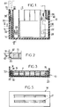
- the male connection block 10 shown in FIGS. 1 to 3 is intended to receive female terminals of the cage type and to be plugged into a complementary female connection block 12 (FIG. 6) equipped with male terminals with contact strips or tabs.
- a complementary female connection block 12 FIG. 6
- Such a block can in particular be used to equip motor vehicles.
- the block 10 comprises a housing 14 intended to receive one or two wafers 16 (the housing can be designed to receive a higher number of wafers).
- the housing 14 and the wafers 16 may be made of polymerized synthetic material containing fillers.
- the housing 14, of rectangular section, has sides connected by a bottom pierced with rows of parallel slots 17. It comprises means defining guide tracks for the pancakes 16 from the start of their introduction. In the case of a housing with two pancakes, these means comprise a single pair of guide projections 18 formed along two opposite sides of the housing and pairs of guide notches 20 located at the intersection of the long sides and the small sides of the shoemaker, both of constant section and corresponding to that of grooves made in the dihedrons of the pancakes.
- a row of several passages, of rectangular section, each intended to receive a terminal 22 (FIGS. 1 and 9) is formed.
- the maximum insertion position of the terminal is determined by its support against an abutment flange 24 provided on the wafers.
- One of the large faces of each wafer is cut out and constitutes elastic pawls 26, the spout of which is intended to engage in one of the two locking holes 28 that each terminal has, on two opposite sides.
- the pawls 26 end in withdrawal with respect to the front end of the wafer and to the abutment rim 24.
- the pawl extends beyond the spout so that its bending causes a displacement of its end which is greater than the displacement caused by the spout, which is a factor favoring the detection of non-snap-fastening.
- a keying groove 30 offset relative to the median plane of the wafer and intended to slide on a keying rib 32 provided on one side of the housing 14
- the housing only intervenes to prevent the insertion of the first wafer when one of its pawls remains raised.
- Means are advantageously provided to avoid likewise the insertion of the second pancake and possibly of the following ones. In the case shown in Figure 6, these means consist of a step 36 on each of the wafers.
- each of the small faces of each wafer is cut to form an elastic finger 38 having a locking spout intended to engage in a corresponding opening 40 of the housing 14.
- each finger 38 is advantageously framed laterally by two protective wings 42 ( Figure 2).
- the means making it possible to fix the male block to the female block may include extensions 44 inserted between the fingers 38 and the body of the pancakes, preventing the withdrawal of the pancakes.
- Figures 7 and 8 show alternative embodiments in which the steps 36, prohibiting the insertion of wafers other than the first when a pawl remains raised, are replaced by other means.
- each wafer which separate the passages have an inclined edge 46 and that of the large faces of the wafer which carries no pawls ends at about two-thirds of the height of the wafer, so as to constitute a support shoulder 48.
- the housing 14 has walls 50 whose end constitutes a stop.
- a connector can consist of a male block of any of the types which have just been described and of a female block 12 of the kind shown in FIG. 6.
- This female block also has sides and a bottom 52 which, this times, is far from the entrance of the block.
- the slots 17 formed in the bottom of the housing 14 and 54 in the bottom 52 are placed in coincidence. Their width is such that they can allow passage to the tabs of male terminals 56 retained in the wafers of the female block 12 and their length is such that they occupy most of the length of the row of slots.
- Figures 3 and 5 show, by way of example, rows of three slots 17, while the housing 14 allows to receive wafers having six passages.
- This arrangement of the slots makes it possible to place, in a given housing, any one of several types of wafer, having transverse passage dimensions and a number of different passages. It is thus possible, depending on the intensity of the current to be passed, to provide wafers intended for terminals having a width of the contact area l varying from one wafer to another, but the same thickness.
- these terminals can be formed by folding a strip doubling the thickness of the tongue, then cutting the end of the tongues.
Landscapes
- Details Of Connecting Devices For Male And Female Coupling (AREA)
- Connector Housings Or Holding Contact Members (AREA)
- Packaging Frangible Articles (AREA)
- Coupling Device And Connection With Printed Circuit (AREA)
Applications Claiming Priority (2)
| Application Number | Priority Date | Filing Date | Title |
|---|---|---|---|
| FR9101820A FR2673050B1 (fr) | 1991-02-15 | 1991-02-15 | Bloc de connexion electrique enfichable et connecteur incorporant un tel bloc. |
| FR9101820 | 1991-02-15 |
Publications (2)
| Publication Number | Publication Date |
|---|---|
| EP0500425A1 EP0500425A1 (fr) | 1992-08-26 |
| EP0500425B1 true EP0500425B1 (fr) | 1995-04-19 |
Family
ID=9409758
Family Applications (1)
| Application Number | Title | Priority Date | Filing Date |
|---|---|---|---|
| EP92400388A Expired - Lifetime EP0500425B1 (fr) | 1991-02-15 | 1992-02-13 | Bloc de connextion électrique enfichable et connecteur incorporant un tel bloc |
Country Status (8)
| Country | Link |
|---|---|
| US (1) | US5190476A (cs) |
| EP (1) | EP0500425B1 (cs) |
| JP (1) | JPH06318479A (cs) |
| BR (1) | BR9200511A (cs) |
| CA (1) | CA2061268C (cs) |
| CS (1) | CS41592A3 (cs) |
| DE (1) | DE69202079T2 (cs) |
| FR (1) | FR2673050B1 (cs) |
Families Citing this family (18)
| Publication number | Priority date | Publication date | Assignee | Title |
|---|---|---|---|---|
| USD350955S (en) | 1992-06-26 | 1994-09-27 | Control Logic (Proprietary) Limited | Electrical receptacle |
| JPH0660936A (ja) * | 1992-08-05 | 1994-03-04 | Yazaki Corp | 合体コネクタ |
| JP2671729B2 (ja) * | 1992-09-29 | 1997-10-29 | 住友電装株式会社 | コネクタ装置 |
| US5320564A (en) * | 1992-11-10 | 1994-06-14 | Burndy Corporation | Track connection system for electrical connectors |
| US5443403A (en) * | 1993-03-10 | 1995-08-22 | The Whitaker Corporation | Composite electrical connector assembly with snap-in housing |
| GB9305347D0 (en) * | 1993-03-16 | 1993-05-05 | Drewnicki Richard | Electrical connector |
| US5346412A (en) * | 1993-07-27 | 1994-09-13 | The Whitaker Corporation | Break away key and latch assembly |
| NL9302007A (nl) * | 1993-11-19 | 1995-06-16 | Framatome Connectors Belgium | Connector voor afgeschermde kabels. |
| FR2734089B1 (fr) * | 1995-05-12 | 1997-07-18 | Framatome Connectors Int | Bloc de connexion modulaire a contacts demontables |
| JP3145271B2 (ja) * | 1995-05-16 | 2001-03-12 | 矢崎総業株式会社 | 低挿入力コネクタ |
| DE59604641D1 (de) * | 1995-06-02 | 2000-04-20 | Siemens Ag | Elektrischer Steckverbinder |
| JPH1021993A (ja) * | 1996-07-04 | 1998-01-23 | Yazaki Corp | コネクタ |
| JPH1083849A (ja) * | 1996-09-11 | 1998-03-31 | Sumitomo Wiring Syst Ltd | 配電ボックス |
| JPH11162552A (ja) * | 1997-12-01 | 1999-06-18 | Yazaki Corp | コネクタ |
| FR2843241A1 (fr) * | 2002-07-31 | 2004-02-06 | Framatome Connectors Int | Dispositif de retention de contact ameliore |
| US7313430B2 (en) * | 2003-08-28 | 2007-12-25 | Medtronic Navigation, Inc. | Method and apparatus for performing stereotactic surgery |
| US8137142B1 (en) | 2011-09-22 | 2012-03-20 | Yazaki North America, Inc. | Connector assembly |
| CZ2013419A3 (cs) | 2013-06-04 | 2014-08-13 | SQS Vláknová optika a.s. | Zásuvné zařízení pro spojování optických a/nebo elektronických konektorů a způsob provádění tohoto spojování |
Family Cites Families (14)
| Publication number | Priority date | Publication date | Assignee | Title |
|---|---|---|---|---|
| FR597454A (cs) * | 1924-05-09 | 1925-11-21 | ||
| FR2538963A1 (fr) * | 1982-12-30 | 1984-07-06 | Labinal | Connecteur electrique |
| US4596436A (en) * | 1985-03-25 | 1986-06-24 | Amp Incorporated | Electrical connector housing assembly comprising housing frame containing housing modules |
| US4682839A (en) * | 1986-01-30 | 1987-07-28 | Crane Electronics, Inc. | Multi-row modular electrical connector |
| US4717359A (en) * | 1986-04-10 | 1988-01-05 | United Technologies Automotive, Inc. | Arrangement for securing electrical terminal in terminal holder |
| US4787864A (en) * | 1987-03-25 | 1988-11-29 | Amp Incorporated | Terminal stabilization and retention system for an electrical connector |
| US4781619A (en) * | 1987-09-18 | 1988-11-01 | Yazaki Corporation | Connector and method of connecting wires thereto |
| US4936798A (en) * | 1988-07-21 | 1990-06-26 | Amp Incorporated | Electrical connector |
| US4900274A (en) * | 1988-12-15 | 1990-02-13 | International Business Machines Corporation | Keying system for assuring proper array configuration of cable cards |
| JP2896783B2 (ja) * | 1989-03-01 | 1999-05-31 | 日本航空電子工業株式会社 | コネクタハウジングの二重ロック構造 |
| US4944688A (en) * | 1989-09-25 | 1990-07-31 | Amp Incorporated | Programmable sealed connector |
| US5026304A (en) * | 1989-12-22 | 1991-06-25 | Amp Incorporated | Connector and connector assembly having improved terminal insertion feature |
| JPH0637581Y2 (ja) * | 1990-02-08 | 1994-09-28 | 矢崎総業株式会社 | コネクタにおける端子金具の係止機構 |
| US5071374A (en) * | 1990-09-24 | 1991-12-10 | Molex Incorporated | Floatable electrical connector with terminal position assurance component |
-
1991
- 1991-02-15 FR FR9101820A patent/FR2673050B1/fr not_active Expired - Lifetime
-
1992
- 1992-02-12 CS CS92415A patent/CS41592A3/cs unknown
- 1992-02-13 DE DE69202079T patent/DE69202079T2/de not_active Expired - Lifetime
- 1992-02-13 EP EP92400388A patent/EP0500425B1/fr not_active Expired - Lifetime
- 1992-02-14 JP JP4059550A patent/JPH06318479A/ja not_active Withdrawn
- 1992-02-14 US US07/835,399 patent/US5190476A/en not_active Expired - Lifetime
- 1992-02-14 BR BR929200511A patent/BR9200511A/pt not_active IP Right Cessation
- 1992-02-14 CA CA002061268A patent/CA2061268C/fr not_active Expired - Fee Related
Also Published As
| Publication number | Publication date |
|---|---|
| EP0500425A1 (fr) | 1992-08-26 |
| US5190476A (en) | 1993-03-02 |
| CS41592A3 (en) | 1992-10-14 |
| JPH06318479A (ja) | 1994-11-15 |
| FR2673050B1 (fr) | 1994-01-28 |
| CA2061268C (fr) | 2001-12-11 |
| DE69202079D1 (de) | 1995-05-24 |
| CA2061268A1 (fr) | 1992-08-16 |
| FR2673050A1 (fr) | 1992-08-21 |
| BR9200511A (pt) | 1992-10-20 |
| DE69202079T2 (de) | 1995-08-17 |
Similar Documents
| Publication | Publication Date | Title |
|---|---|---|
| EP0500425B1 (fr) | Bloc de connextion électrique enfichable et connecteur incorporant un tel bloc | |
| EP0726619B1 (fr) | Connecteur électrique à grille de verouillage de contacts et tiroir | |
| EP0625809B1 (fr) | Connecteur électrique à tiroir d'insertion et d'extraction | |
| EP0123590A1 (fr) | Connecteur perfectionné | |
| FR2644302A1 (fr) | Assemblage d'interconnexion electrique | |
| EP0207842B1 (fr) | Perfectionnements aux connecteurs électriques | |
| FR2730588A1 (fr) | Perfectionnements aux connecteurs electriques | |
| FR2648628A1 (fr) | Systeme de connecteurs electriques | |
| EP0723314B1 (fr) | Connecteur électrique | |
| FR2778501A1 (fr) | Connecteur electrique a verrouillage des bornes de contact | |
| EP0670614A1 (fr) | Connecteur pour canalisation électrique | |
| EP2680379B1 (fr) | Ensemble d'appareils électriques modulaires avec dispositif de verrouillage sur un rail de montage | |
| EP0581638B1 (fr) | Connecteur électrique | |
| FR2803111A1 (fr) | Connecteur electrique | |
| EP0673084A1 (fr) | Elément de boîtier de connecteur électrique | |
| EP0519815A1 (fr) | Connecteur électrique | |
| EP0726618B1 (fr) | Connecteur électrique à grille de verrouillage des contacts | |
| EP0742608B1 (fr) | Module de connexion à contacts démontables et bloc de connexion en faisant application | |
| EP0718921A1 (fr) | Connecteur à verrouillage des bornes par grille | |
| FR2822597A1 (fr) | Connecteur d'usage commun a objets multiples et procede de fabrication du connecteur | |
| FR2754943A1 (fr) | Connecteur electrique a verrouillage des bornes de contact | |
| EP0718920B1 (fr) | Connecteur à grille de verrouillage secondaire des bornes | |
| EP0814541B1 (fr) | Connecteur électrique | |
| FR2678779A1 (fr) | Bloc de connexion electrique enfichable, a verrouillage des bornes de contact. | |
| FR2747846A1 (fr) | Montage d'organes de contacts electriques dans des elements de boitiers de connecteurs electriques |
Legal Events
| Date | Code | Title | Description |
|---|---|---|---|
| PUAI | Public reference made under article 153(3) epc to a published international application that has entered the european phase |
Free format text: ORIGINAL CODE: 0009012 |
|
| AK | Designated contracting states |
Kind code of ref document: A1 Designated state(s): DE GB IT NL SE |
|
| 17P | Request for examination filed |
Effective date: 19920905 |
|
| 17Q | First examination report despatched |
Effective date: 19940919 |
|
| RAP1 | Party data changed (applicant data changed or rights of an application transferred) |
Owner name: FRAMATOME CONNECTORS CONNECTRAL |
|
| GRAA | (expected) grant |
Free format text: ORIGINAL CODE: 0009210 |
|
| AK | Designated contracting states |
Kind code of ref document: B1 Designated state(s): DE GB IT NL SE |
|
| GBT | Gb: translation of ep patent filed (gb section 77(6)(a)/1977) |
Effective date: 19950425 |
|
| REF | Corresponds to: |
Ref document number: 69202079 Country of ref document: DE Date of ref document: 19950524 |
|
| ITF | It: translation for a ep patent filed | ||
| PLBE | No opposition filed within time limit |
Free format text: ORIGINAL CODE: 0009261 |
|
| STAA | Information on the status of an ep patent application or granted ep patent |
Free format text: STATUS: NO OPPOSITION FILED WITHIN TIME LIMIT |
|
| 26N | No opposition filed | ||
| REG | Reference to a national code |
Ref country code: GB Ref legal event code: IF02 |
|
| PGFP | Annual fee paid to national office [announced via postgrant information from national office to epo] |
Ref country code: SE Payment date: 20050215 Year of fee payment: 14 |
|
| PGFP | Annual fee paid to national office [announced via postgrant information from national office to epo] |
Ref country code: NL Payment date: 20050228 Year of fee payment: 14 |
|
| PGFP | Annual fee paid to national office [announced via postgrant information from national office to epo] |
Ref country code: GB Payment date: 20060109 Year of fee payment: 15 |
|
| PG25 | Lapsed in a contracting state [announced via postgrant information from national office to epo] |
Ref country code: SE Free format text: LAPSE BECAUSE OF NON-PAYMENT OF DUE FEES Effective date: 20060214 |
|
| PG25 | Lapsed in a contracting state [announced via postgrant information from national office to epo] |
Ref country code: NL Free format text: LAPSE BECAUSE OF NON-PAYMENT OF DUE FEES Effective date: 20060901 |
|
| EUG | Se: european patent has lapsed | ||
| NLV4 | Nl: lapsed or anulled due to non-payment of the annual fee |
Effective date: 20060901 |
|
| GBPC | Gb: european patent ceased through non-payment of renewal fee |
Effective date: 20070213 |
|
| PG25 | Lapsed in a contracting state [announced via postgrant information from national office to epo] |
Ref country code: GB Free format text: LAPSE BECAUSE OF NON-PAYMENT OF DUE FEES Effective date: 20070213 |
|
| PGFP | Annual fee paid to national office [announced via postgrant information from national office to epo] |
Ref country code: DE Payment date: 20110228 Year of fee payment: 20 Ref country code: IT Payment date: 20110219 Year of fee payment: 20 |
|
| REG | Reference to a national code |
Ref country code: DE Ref legal event code: R071 Ref document number: 69202079 Country of ref document: DE |
|
| REG | Reference to a national code |
Ref country code: DE Ref legal event code: R071 Ref document number: 69202079 Country of ref document: DE |
|
| PG25 | Lapsed in a contracting state [announced via postgrant information from national office to epo] |
Ref country code: DE Free format text: LAPSE BECAUSE OF EXPIRATION OF PROTECTION Effective date: 20120214 |