EP0499184B1 - Procédé de combustion de commande simultanée d'acides d'azote et de produits à combustion incomplète - Google Patents
Procédé de combustion de commande simultanée d'acides d'azote et de produits à combustion incomplète Download PDFInfo
- Publication number
- EP0499184B1 EP0499184B1 EP92102208A EP92102208A EP0499184B1 EP 0499184 B1 EP0499184 B1 EP 0499184B1 EP 92102208 A EP92102208 A EP 92102208A EP 92102208 A EP92102208 A EP 92102208A EP 0499184 B1 EP0499184 B1 EP 0499184B1
- Authority
- EP
- European Patent Office
- Prior art keywords
- combustion
- combustion zone
- oxidant
- high velocity
- products
- Prior art date
- Legal status (The legal status is an assumption and is not a legal conclusion. Google has not performed a legal analysis and makes no representation as to the accuracy of the status listed.)
- Expired - Lifetime
Links
Images

Classifications
-
- F—MECHANICAL ENGINEERING; LIGHTING; HEATING; WEAPONS; BLASTING
- F23—COMBUSTION APPARATUS; COMBUSTION PROCESSES
- F23C—METHODS OR APPARATUS FOR COMBUSTION USING FLUID FUEL OR SOLID FUEL SUSPENDED IN A CARRIER GAS OR AIR
- F23C9/00—Combustion apparatus characterised by arrangements for returning combustion products or flue gases to the combustion chamber
- F23C9/006—Combustion apparatus characterised by arrangements for returning combustion products or flue gases to the combustion chamber the recirculation taking place in the combustion chamber
-
- F—MECHANICAL ENGINEERING; LIGHTING; HEATING; WEAPONS; BLASTING
- F23—COMBUSTION APPARATUS; COMBUSTION PROCESSES
- F23G—CREMATION FURNACES; CONSUMING WASTE PRODUCTS BY COMBUSTION
- F23G5/00—Incineration of waste; Incinerator constructions; Details, accessories or control therefor
- F23G5/08—Incineration of waste; Incinerator constructions; Details, accessories or control therefor having supplementary heating
- F23G5/14—Incineration of waste; Incinerator constructions; Details, accessories or control therefor having supplementary heating including secondary combustion
- F23G5/16—Incineration of waste; Incinerator constructions; Details, accessories or control therefor having supplementary heating including secondary combustion in a separate combustion chamber
-
- F—MECHANICAL ENGINEERING; LIGHTING; HEATING; WEAPONS; BLASTING
- F23—COMBUSTION APPARATUS; COMBUSTION PROCESSES
- F23L—SUPPLYING AIR OR NON-COMBUSTIBLE LIQUIDS OR GASES TO COMBUSTION APPARATUS IN GENERAL ; VALVES OR DAMPERS SPECIALLY ADAPTED FOR CONTROLLING AIR SUPPLY OR DRAUGHT IN COMBUSTION APPARATUS; INDUCING DRAUGHT IN COMBUSTION APPARATUS; TOPS FOR CHIMNEYS OR VENTILATING SHAFTS; TERMINALS FOR FLUES
- F23L7/00—Supplying non-combustible liquids or gases, other than air, to the fire, e.g. oxygen, steam
-
- F—MECHANICAL ENGINEERING; LIGHTING; HEATING; WEAPONS; BLASTING
- F23—COMBUSTION APPARATUS; COMBUSTION PROCESSES
- F23N—REGULATING OR CONTROLLING COMBUSTION
- F23N1/00—Regulating fuel supply
- F23N1/02—Regulating fuel supply conjointly with air supply
- F23N1/022—Regulating fuel supply conjointly with air supply using electronic means
-
- F—MECHANICAL ENGINEERING; LIGHTING; HEATING; WEAPONS; BLASTING
- F23—COMBUSTION APPARATUS; COMBUSTION PROCESSES
- F23N—REGULATING OR CONTROLLING COMBUSTION
- F23N5/00—Systems for controlling combustion
- F23N5/003—Systems for controlling combustion using detectors sensitive to combustion gas properties
-
- F—MECHANICAL ENGINEERING; LIGHTING; HEATING; WEAPONS; BLASTING
- F23—COMBUSTION APPARATUS; COMBUSTION PROCESSES
- F23C—METHODS OR APPARATUS FOR COMBUSTION USING FLUID FUEL OR SOLID FUEL SUSPENDED IN A CARRIER GAS OR AIR
- F23C2900/00—Special features of, or arrangements for combustion apparatus using fluid fuels or solid fuels suspended in air; Combustion processes therefor
- F23C2900/06041—Staged supply of oxidant
-
- F—MECHANICAL ENGINEERING; LIGHTING; HEATING; WEAPONS; BLASTING
- F23—COMBUSTION APPARATUS; COMBUSTION PROCESSES
- F23C—METHODS OR APPARATUS FOR COMBUSTION USING FLUID FUEL OR SOLID FUEL SUSPENDED IN A CARRIER GAS OR AIR
- F23C2900/00—Special features of, or arrangements for combustion apparatus using fluid fuels or solid fuels suspended in air; Combustion processes therefor
- F23C2900/09002—Specific devices inducing or forcing flue gas recirculation
-
- F—MECHANICAL ENGINEERING; LIGHTING; HEATING; WEAPONS; BLASTING
- F23—COMBUSTION APPARATUS; COMBUSTION PROCESSES
- F23G—CREMATION FURNACES; CONSUMING WASTE PRODUCTS BY COMBUSTION
- F23G2202/00—Combustion
- F23G2202/10—Combustion in two or more stages
- F23G2202/101—Combustion in two or more stages with controlled oxidant supply
-
- F—MECHANICAL ENGINEERING; LIGHTING; HEATING; WEAPONS; BLASTING
- F23—COMBUSTION APPARATUS; COMBUSTION PROCESSES
- F23G—CREMATION FURNACES; CONSUMING WASTE PRODUCTS BY COMBUSTION
- F23G2202/00—Combustion
- F23G2202/10—Combustion in two or more stages
- F23G2202/102—Combustion in two or more stages with supplementary heating
-
- F—MECHANICAL ENGINEERING; LIGHTING; HEATING; WEAPONS; BLASTING
- F23—COMBUSTION APPARATUS; COMBUSTION PROCESSES
- F23G—CREMATION FURNACES; CONSUMING WASTE PRODUCTS BY COMBUSTION
- F23G2207/00—Control
- F23G2207/10—Arrangement of sensing devices
- F23G2207/103—Arrangement of sensing devices for oxygen
-
- F—MECHANICAL ENGINEERING; LIGHTING; HEATING; WEAPONS; BLASTING
- F23—COMBUSTION APPARATUS; COMBUSTION PROCESSES
- F23G—CREMATION FURNACES; CONSUMING WASTE PRODUCTS BY COMBUSTION
- F23G2209/00—Specific waste
- F23G2209/12—Sludge, slurries or mixtures of liquids
-
- F—MECHANICAL ENGINEERING; LIGHTING; HEATING; WEAPONS; BLASTING
- F23—COMBUSTION APPARATUS; COMBUSTION PROCESSES
- F23G—CREMATION FURNACES; CONSUMING WASTE PRODUCTS BY COMBUSTION
- F23G2209/00—Specific waste
- F23G2209/24—Contaminated soil; foundry sand
-
- F—MECHANICAL ENGINEERING; LIGHTING; HEATING; WEAPONS; BLASTING
- F23—COMBUSTION APPARATUS; COMBUSTION PROCESSES
- F23G—CREMATION FURNACES; CONSUMING WASTE PRODUCTS BY COMBUSTION
- F23G2900/00—Special features of, or arrangements for incinerators
- F23G2900/52001—Rotary drums with co-current flows of waste and gas
-
- F—MECHANICAL ENGINEERING; LIGHTING; HEATING; WEAPONS; BLASTING
- F23—COMBUSTION APPARATUS; COMBUSTION PROCESSES
- F23L—SUPPLYING AIR OR NON-COMBUSTIBLE LIQUIDS OR GASES TO COMBUSTION APPARATUS IN GENERAL ; VALVES OR DAMPERS SPECIALLY ADAPTED FOR CONTROLLING AIR SUPPLY OR DRAUGHT IN COMBUSTION APPARATUS; INDUCING DRAUGHT IN COMBUSTION APPARATUS; TOPS FOR CHIMNEYS OR VENTILATING SHAFTS; TERMINALS FOR FLUES
- F23L2900/00—Special arrangements for supplying or treating air or oxidant for combustion; Injecting inert gas, water or steam into the combustion chamber
- F23L2900/07005—Injecting pure oxygen or oxygen enriched air
-
- F—MECHANICAL ENGINEERING; LIGHTING; HEATING; WEAPONS; BLASTING
- F23—COMBUSTION APPARATUS; COMBUSTION PROCESSES
- F23L—SUPPLYING AIR OR NON-COMBUSTIBLE LIQUIDS OR GASES TO COMBUSTION APPARATUS IN GENERAL ; VALVES OR DAMPERS SPECIALLY ADAPTED FOR CONTROLLING AIR SUPPLY OR DRAUGHT IN COMBUSTION APPARATUS; INDUCING DRAUGHT IN COMBUSTION APPARATUS; TOPS FOR CHIMNEYS OR VENTILATING SHAFTS; TERMINALS FOR FLUES
- F23L2900/00—Special arrangements for supplying or treating air or oxidant for combustion; Injecting inert gas, water or steam into the combustion chamber
- F23L2900/07006—Control of the oxygen supply
-
- F—MECHANICAL ENGINEERING; LIGHTING; HEATING; WEAPONS; BLASTING
- F23—COMBUSTION APPARATUS; COMBUSTION PROCESSES
- F23L—SUPPLYING AIR OR NON-COMBUSTIBLE LIQUIDS OR GASES TO COMBUSTION APPARATUS IN GENERAL ; VALVES OR DAMPERS SPECIALLY ADAPTED FOR CONTROLLING AIR SUPPLY OR DRAUGHT IN COMBUSTION APPARATUS; INDUCING DRAUGHT IN COMBUSTION APPARATUS; TOPS FOR CHIMNEYS OR VENTILATING SHAFTS; TERMINALS FOR FLUES
- F23L2900/00—Special arrangements for supplying or treating air or oxidant for combustion; Injecting inert gas, water or steam into the combustion chamber
- F23L2900/07008—Injection of water into the combustion chamber
-
- F—MECHANICAL ENGINEERING; LIGHTING; HEATING; WEAPONS; BLASTING
- F23—COMBUSTION APPARATUS; COMBUSTION PROCESSES
- F23N—REGULATING OR CONTROLLING COMBUSTION
- F23N2237/00—Controlling
- F23N2237/16—Controlling secondary air
-
- Y—GENERAL TAGGING OF NEW TECHNOLOGICAL DEVELOPMENTS; GENERAL TAGGING OF CROSS-SECTIONAL TECHNOLOGIES SPANNING OVER SEVERAL SECTIONS OF THE IPC; TECHNICAL SUBJECTS COVERED BY FORMER USPC CROSS-REFERENCE ART COLLECTIONS [XRACs] AND DIGESTS
- Y02—TECHNOLOGIES OR APPLICATIONS FOR MITIGATION OR ADAPTATION AGAINST CLIMATE CHANGE
- Y02E—REDUCTION OF GREENHOUSE GAS [GHG] EMISSIONS, RELATED TO ENERGY GENERATION, TRANSMISSION OR DISTRIBUTION
- Y02E20/00—Combustion technologies with mitigation potential
- Y02E20/34—Indirect CO2mitigation, i.e. by acting on non CO2directly related matters of the process, e.g. pre-heating or heat recovery
Definitions
- This invention relates generally to combustion and is particularly applicable to the incineration of waste such as hazardous waste.
- GB-A-2 064 735 discloses an incineration process in which combustible material is burnt out and degassed in a first combustion zone under pyrolytic conditions. Incompletely burnt gases and gas-borne particles are transferred from the first combustion zone to a second combustion zone through an upper passage, whereas the remainder of the combustible material is transferred from the first to the second combustion zone through a lower passage.
- By the disposition of the upper passage a circulatory gas motion is caused within the second combustion zone whereby the gases entering the second combustion zone move along a helical, downwardly directed path while being burnt and yielding heat for the melting of material present in the lower part of the second combustion zone.
- Air or oxygen is supplied to the second combustion zone through bottom nozzles in order to effect decarbonization of the melt. Additional heat may be supplied to the lower part of the second combustion zone by a gas burner being provided near the bottom of the second combustion zone.
- a third combustion zone extends from the top end of the second combustion zone, said third combustion zone being provided with nozzles for supplying air, oxygen or heat to further raise the temperature of the light components leaving the second combustion zone, and to provide for a final burnout.
- US-A-3 547 056 discloses an incinerator system having first and second combustion chambers joined by a venturi throat member. Burners supplied with fuel and air are used both for the primary and the secondary combustion.
- a pair of burner nozzles is disposed within the first combustion chamber, one of said nozzles being oriented to direct the effluent thereof against waste being burned in the first combustion chamber while the other nozzle being positioned so that the periphery of an air/fuel jet discharged by said nozzle essentially corresponds to the venturi throat diameter to thereby pump gases and particulate material through the throat and into the second combustion chamber.
- Air also is introduced into the first combustion chamber through an opening in one of the end walls of the first combustion chamber.
- the venturi throat defines the single inlet to the second combustion chamber.
- a first burner is disposed in the first combustion chamber and a second burner is disposed in the second combustion chamber.
- EP-A-0 426 471 discloses a waste incinerator comprising a first combustion chamber for receiving waste material to be burned to yield combustion gases, and a second combustion chamber into which said combustion gases are transferred from the first combustion chamber.
- the second combustion chamber includes an air mixing section containing air mixing means for supplying outside air, and a plurality of burners is disposed in such a way, that the flames extending from the burners form a vortex to assist the mixing and burning of the combustion gases.
- the oxygen may be injected into the combustion zone in the form of air, oxygen-enriched air or technically pure oxygen.
- the higher is the oxygen concentration of the oxidant the greater is the tendency for the subsequent combustion to form nitrogen oxides (NO x ) which are themselves undesirable pollutants resulting from combustion processes.
- PICs environmental pollutant
- NO x nitrogen oxides
- a method for combusting material with controlled generation of both nitrogen oxides and products of incomplete combustion comprising:
- oxidant jet diameter means the diameter of the oxidant stream at the point where it emerges from the injection device such as a nozzle.
- smoke means a black substance, comprising very small particles of carbon or heavy hydrocarbons, which appears in smoke often resulting from incomplete combustion.
- blow-off velocity means the maximum oxidant jet velocity, as measured at the orifice, that will maintain a flame attached to the orifice when the oxidant jet is surrounded by gaseous fuel.
- Figure 1 is a simplified schematic diagram of one embodiment of the invention carried out in conjunction with the incineration of hazardous waste.
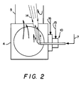
- Figure 2 is a more detailed view of the embodiment illustrated in Figure 1 showing in greater detail the injection of high velocity oxidant and the aspiration thereinto of exhaust gases.
- combustible material is provided into a first combustion zone.
- the combustible material or fuel may be in solid, liquid, gaseous or mixed phase form and may be provided into the first combustion zone separately from or with the oxidant for combustion.
- the invention will have particular utility with combustible material which has a highly variable heating value per unit volume and/or which is supplied into the first combustion zone at a highly variable rate.
- Examples of combustible material or fuel which may be employed with the combustion method of this invention include coal, wood, lignite, heavy oil, trash, solid and/or liquid waste, aqueous plant effluent and hazardous waste.
- gaseous fuel will volatize from the solid or liquid.
- the oxidant employed in the first combustion zone may be air, oxygen-enriched air and/or technically pure oxygen and may be supplied with the combustible material such as through a burner or as a separate oxidant stream such as through a lance. Air may also pass into the first combustion zone by infiltration.
- the combustible material is combusted to produce gaseous exhaust which comprises products of complete combustion, such as carbon dioxide and water vapor, and also products of incomplete combustion.
- a product of incomplete combustion or PIC may be defined as a species which can undergo oxidation or further oxidation under combustion zone conditions of temperature and pressure. Examples of well known PICs include carbon monoxide, hydrocarbons, soot and chlorinated hydrocarbons such as dioxins and furans.
- the gaseous exhaust is then passed from the first combustion zone into a second combustion zone which may be integral with the first combustion zone or may be separate from the first combustion zone and connected therewith by a conduit or other passageway.
- the first combustion zone may be the primary combustion chamber of an incineration system and the second combustion zone may be the secondary combustion chamber of such a system.
- the primary combustion chamber of an incineration system comprises a rotary kiln.
- the primary combustion chamber is often used for handling solid or sludge waste while the secondary combustion chamber is used to treat the gaseous exhaust from the primary combustion chamber to ensure good destruction of the waste by operating at a higher temperature and providing sufficient gas residence time to ensure the destruction of the waste.
- the high velocity oxidant is technically pure oxygen having an oxygen concentration of 99.5 percent or more.
- the high velocity oxidant will have a velocity of at least 300 feet per second and generally the velocity will be within the range of from 400 to 1500 feet per second. The velocity is sufficiently high to cause exhaust gases to aspirate into the oxidant. The aspiration may occur within the second combustion zone and/or may occur upstream of the second combustion zone.
- the aspiration enables the exhaust gas and in particular the PICs within the exhaust gas to intimately mix with the oxidant resulting in the subsequent combustion being stable with the avoidance of hot spots which would favor NO x formation and would cause refractory damage.
- the products of complete combustion from the combustion reaction e.g. carbon dioxide and water vapor, within the exhaust gas which are also aspirated into the high velocity oxidant serve as ballast for the combustion reaction whereby the combustion reaction is spread out and heat from the combustion reaction is absorbed by this heat sink. This further inhibits NO x formation.
- the high velocity oxidant is injected into the second combustion zone in a manner such that there is no impingement of the oxidant jet on the walls of the second combustion zone within about 300 oxidant jet diameters from the high velocity oxidant injection point.
- the high velocity oxidant is injected into the second combustion zone with an orientation substantially parallel to the axial direction of the second combustion zone. In this way local overheating which may cause refractory damage as well as excessive NO x generation is avoided.
- the high velocity oxidant is injected into the second combustion zone in a plurality of streams.
- the number of high velocity oxidant streams will be within the range of from 30 to 50.
- the plurality of high velocity oxidant streams may be injected parallel to each other. However, since neighboring parallel streams would generally immediately merge into a single jet, it is preferred that at least two, and preferably most of the plurality of high velocity oxidant streams be injected as outwardly diverging streams. In a particularly preferred embodiment, the outwardly diverging streams in close proximity converge after aspiration of PICs-containing exhaust gas into the oxidant.
- the use of a plurality of streams improves the overall aspiration of exhaust gas into the oxidant and the use of outwardly diverging oxidant streams further improves the completeness of the aspiration, thus serving to ensure that PICs do not bypass the flame zone in the second combustion zone while further retarding NO x formation.
- the downstream convergence of the outwardly divergent streams bring the PICs together with the oxidant in a manner which improves the complete combustion of these species within the second combustion zone. It also prevents flame impingement on the furnace or combustion zone walls so as to avoid overheating of refractory or slagging.
- a preferred embodiment of this invention involves the injection of the oxidant through a plurality of orifices as a cluster, such as on a nozzle, such that the farther away from the center of the cluster, the greater is the divergent angle of the orifice.
- This embodiment has the advantage of promoting staged combustion thus further reducing flame temperature and NO x formation.
- atomized water or another coolant may be provided into the second combustion zone.
- auxiliary coolant it is preferred that it be provided in such manner that it also is aspirated into the high velocity oxidant either prior to combustion or during the combustion.
- the first combustion zone be operated under pyrolytic or fuel-rich conditions.
- Fuel-rich conditions within the first combustion reduce the gas volumetric flow within the first combustion zone, thus reducing the particulate carryover to the second combustion zone.
- fuel-rich conditions within the first combustion zone could lead to a more stable temperature and thus to a more stable generation of combustible vapors which reduces the fluctuation of oxygen demand while significantly reducing the fuel requirement in the second combustion zone. As a result a higher throughput can be achieved.
- the initial jet velocity is too high for combustion to take place.
- the gas residence time at conditions suitable for NO x generation i.e. high temperature, excess oxygen
- the aspiration effect of the high velocity jet creates intense mixing and strong recirculation of the furnace gas. This minimizes the probability of local excess oxygen.
- the intensive mixing of the furnace gas in a fuel-rich combustion zone promotes the gasification of the organic materials to form gaseous fuels, such as carbon monoxide, hydrogen and methane, while it minimizes the formation of soot particles.
- Soot particles are a source of PICs and may be difficult to burn out in the secondary combustion zone once they are formed.
- volatiles would undergo chemical reactions including pyrolysis (thermal cracking), partial oxidation (also known as oxidative pyrolysis) or complete oxidation. If the local oxygen/carbon ratio is low and/or the free radical concentrations are low, heavy hydrocarbons (soot) are formed through polymerization (recombination) reactions. With the use of high velocity jets to enhance the mixing and recirculation of the gas stream, a more uniform profile of local oxygen/carbon ratios is obtained.
- Oxygen can be supplied not only by oxygen molecules but also by steam and carbon dioxide.
- Internal recirculation within the combustion zone caused by the high velocity oxidant enables stream and/or carbon dioxide generated by the drying or combustion of material within the combustion zone, such as solid waste, to be beneficially used for soot reduction.
- the vigorous mixing and recirculation within the combustion zone distributes free radicals uniformly throughout the combustion zone thus helping to further reduce the formation of soot.
- the preferred method of the invention is to use multiple streams of jets so that smaller diameter jets can be used.
- the diameter of each jet is less than 1/100 of the diameter or width of the combustion chamber or zone. The smaller the diameter, the quicker the aspiration takes place and the smaller is the turbulence scale.
- a particularly preferred embodiment of the invention is the use of the multiple-stream, divergent-converging configuration described earlier.
- the luminous flame size is increased due to this divergent-converging configuration compared to a single stream flame, leading to greater radiative heat transfer to the heat load.
- the velocity of the high velocity jet or jets will generally be within the range of from 400 to 1500 feet per second.
- the second combustion zone be operated under oxidative or oxygen-rich conditions. This ensures that all combustibles are completely combusted so that undesired emissions to the atmosphere are eliminated.
- the injection rate and duration of the high velocity oxidant injected into the second combustion zone may be increased or decreased in order to maintain the desired level of excess oxygen within the second combustions zone.
- the primary way of maintaining the desired level of excess oxygen within the second combustion zone is to monitor the oxygen concentration within the second combustion zone or within the effluent from the second combustion zone and adjust the high velocity oxidant flow accordingly.
- a preferred supplemental method of maintaining a sufficient level of excess oxygen within the second combustion zone is to monitor the carbon monoxide concentration within the second combustion zone or within the effluent and to increase the oxygen concentration set point or increase the oxidant flow accordingly.
- Other parameters of the effluent which may be monitored to maintain the desired oxidative conditions within the second combustion zone include opacity and luminosity.
- Example is provided to further illustrate the invention and the benefits attainable thereby.
- the Example is not intended to be limiting.
- hazardous waste comprising oily sludge and contaminated soil was provided at a rate of 4.1 tons per hour through input means 1 into rotary kiln 2 which was the first combustion zone of the invention.
- Natural gas 17 and air 18 were provided into kiln 2 through burner 3 and oxygen 19 was provided into kiln 2 through lance 20.
- the hazardous waste was combusted under pyrolytic conditions to produce exhaust gas which included products of incomplete combustion.
- the PICs comprised carbon monoxide, methane and other unknown organic components.
- the oxygen flow into the rotary kiln was adjusted to maintain the kiln 2 exit temperature near the desired level which ensured the removal of hazardous waste from the ash without overheating the ash.
- the gaseous exhaust was passed from kiln 2 into transition chamber 4 and from there into secondary combustion chamber 5.
- Chambers 4 and 5 are the second combustion zone of this invention.
- a small amount of natural gas 15 and air 16 were also supplied through a burner 10 to assist the combustion within chamber 4.
- Atomized water spray 9 was also supplied into chamber 4.
- the gaseous exhaust and the atomized water were aspirated into the high velocity oxidant streams and combustion was carried out in transition chamber 4 and in secondary combustion chamber 5.
- Oxidative conditions were maintained throughout the combustion in chamber 5 by monitoring the oxygen concentration of the flue gas at the exit of chamber 5 as a process variable.
- the process variable was compared with a desired set point to determine the desired flowrate of oxygen using a proportional-integral-derivative (PID) controller as indicated by line 21 and the oxygen flow rate was increased whenever the oxygen level in the effluent fell below a predetermined level.
- PID proportional-integral-derivative
- Exhaust or effluent from chamber 5 was passed through spray tower 11 and baghouse 12 and then exhausted to the atmosphere through stack 13. There were no appreciable levels of carbon monoxide in the exhaust gases passing up stack 13 thus indicating that all PICs were completely combusted. Minimal soot formation was observed in the combustion process. Moreover the NO x level was well within acceptable levels.
Claims (11)
- Procédé de combustion de produits avec génération contrôlée à la fois d'oxydes d'azote et de produits à combustion incomplète comprenant :(A) une combustion des produits dans une première zone de combustion (2) destinée à produire un échappement gazeux contenant des produits à combustion incomplète et des produits à combustion complète ;(B) un passage de l'échappement gazeux depuis la première zone de combustion (2) dans une seconde zone de combustion (4,5) ayant une largeur et une direction axiale ;(C) une injection à travers une lance (6) avec une orientation sensiblement parallèle à ladite direction axiale d'au moins un jet (8) d'oxydant (7), sans combustible, ayant un diamètre inférieur à 1/100 de la largeur de la seconde zone de combustion (4, 5) et ayant une concentration en oxygène d'au moins 30 pour cent, à l'intérieur de la seconde zone de combustion à une vitesse élevée d'au moins 91,4 m/s (300 pieds par seconde) ;(D) une aspiration des produits à combustion incomplète contenus dans ledit échappement gazeux dans l'oxydant à vitesse élevée (7) ;(E) une combustion des produits à combustion incomplète aspirés dans l'oxydant à vitesse élevée (7) avec ledit oxydant à vitesse élevée à l'intérieur de la seconde zone de combustion (4,5) pour réaliser une combustion stable grâce au mélange des produits à combustion incomplète aspirés avec l'oxydant à vitesse élevée ; et(F) une propagation de la réaction de combustion par aspiration des produits à combustion complète contenus dans ledit échappement gazeux dans l'oxydant (7), lesdits produits à combustion complète servant également de dissipateur de chaleur, pour inhiber la formation de NOx.
- Procédé selon la revendication 1, dans lequel l'oxydant à vitesse élevée (7) est injecté dans plusieurs jets (8).
- Procédé selon la revendication 1, dans lequel l'oxydant à vitesse élevée (7) est de l'oxygène pur techniquement.
- Procédé selon la revendication 1 comprenant en plus l'aspiration du réfrigérant (9) dans l'oxydant à vitesse élevée (7).
- Procédé selon la revendication 4, dans lequel le réfrigérant (9) est de l'eau atomisée.
- Procédé selon la revendication 1, dans lequel l'aspiration des produits à combustion incomplète et des produits à combustion complète dans l'oxydant à vitesse élevée (7) s'effectue à l'intérieur de la seconde zone de combustion (4,5).
- Procédé selon la revendication 1, dans lequel la combustion à l'intérieur de la première zone de combustion (2) est réalisée dans des conditions de pyrolyse.
- Procédé selon la revendication 1, dans lequel la combustion à l'intérieur de la seconde zone de combustion (4,5) est réalisée dans des conditions d'oxydation.
- Procédé selon la revendication 1, dans lequel la combustion à l'intérieur de la première zone de combustion (2) est réalisée dans des conditions de pyrolyse et la combustion à l'intérieur de la seconde zone de combustion (4,5) est réalisée dans des conditions d'oxydation.
- Procédé selon la revendication 1, dans lequel le niveau d'oxygène à l'intérieur de la seconde zone de combustion (4,5) est maintenu à un niveau souhaité en surveillant le niveau d'oxygène à l'intérieur de la seconde zone de combustion ou contenu dans l'effluent provenant de la seconde zone de combustion et en augmentant le débit d'oxydant à vitesse élevée (7) à l'intérieur de la seconde zone de combustion quand le niveau d'oxygène contenu dans l'effluent descend au-dessous d'un niveau prédéterminé.
- Procédé selon la revendication 1, dans lequel le niveau d'oxygène à l'intérieur de la seconde zone de combustion (4,5) est maintenu à un niveau souhaité en surveillant le niveau de monoxyde de carbone à l'intérieur de la seconde zone de combustion ou contenu dans l'effluent provenant de la seconde zone de combustion et en augmentant le débit d'oxydant à vitesse élevée (7) à l'intérieur de la seconde zone de combustion quand le niveau de monoxyde de carbone à l'intérieur de la seconde zone de combustion ou contenu dans l'effluent excède un niveau prédéterminé.
Priority Applications (1)
| Application Number | Priority Date | Filing Date | Title |
|---|---|---|---|
| EP95104382A EP0663564B1 (fr) | 1991-02-11 | 1992-02-10 | Procédé de commande simultanée de la combustion d'acides d'azote et de produits à combustion incomplête |
Applications Claiming Priority (2)
| Application Number | Priority Date | Filing Date | Title |
|---|---|---|---|
| US65337091A | 1991-02-11 | 1991-02-11 | |
| US653370 | 1991-02-11 |
Related Child Applications (2)
| Application Number | Title | Priority Date | Filing Date |
|---|---|---|---|
| EP95104382.7 Division-Into | 1992-02-10 | ||
| EP95104382A Division EP0663564B1 (fr) | 1991-02-11 | 1992-02-10 | Procédé de commande simultanée de la combustion d'acides d'azote et de produits à combustion incomplête |
Publications (4)
| Publication Number | Publication Date |
|---|---|
| EP0499184A2 EP0499184A2 (fr) | 1992-08-19 |
| EP0499184A3 EP0499184A3 (en) | 1993-03-03 |
| EP0499184B1 true EP0499184B1 (fr) | 1996-03-27 |
| EP0499184B2 EP0499184B2 (fr) | 1999-03-17 |
Family
ID=24620584
Family Applications (2)
| Application Number | Title | Priority Date | Filing Date |
|---|---|---|---|
| EP92102208A Expired - Lifetime EP0499184B2 (fr) | 1991-02-11 | 1992-02-10 | Procédé de combustion de commande simultanée d'acides d'azote et de produits à combustion incomplète |
| EP95104382A Expired - Lifetime EP0663564B1 (fr) | 1991-02-11 | 1992-02-10 | Procédé de commande simultanée de la combustion d'acides d'azote et de produits à combustion incomplête |
Family Applications After (1)
| Application Number | Title | Priority Date | Filing Date |
|---|---|---|---|
| EP95104382A Expired - Lifetime EP0663564B1 (fr) | 1991-02-11 | 1992-02-10 | Procédé de commande simultanée de la combustion d'acides d'azote et de produits à combustion incomplête |
Country Status (9)
| Country | Link |
|---|---|
| EP (2) | EP0499184B2 (fr) |
| JP (1) | JP2870675B2 (fr) |
| KR (1) | KR0177830B1 (fr) |
| BR (1) | BR9200444A (fr) |
| CA (1) | CA2060953C (fr) |
| DE (2) | DE69209340T3 (fr) |
| DK (2) | DK0663564T3 (fr) |
| ES (2) | ES2085501T5 (fr) |
| MX (1) | MX9200562A (fr) |
Families Citing this family (6)
| Publication number | Priority date | Publication date | Assignee | Title |
|---|---|---|---|---|
| GB2272752A (en) * | 1992-11-18 | 1994-05-25 | Boc Group Plc | Incinerator |
| CH691404A5 (de) * | 1995-10-06 | 2001-07-13 | Von Roll Umwelttechnik Ag | Verfahren zur thermischen Entsorgung von losem Müll. |
| JP3489977B2 (ja) * | 1997-09-10 | 2004-01-26 | 株式会社クボタ | キルン炉の燃焼空気制御方法 |
| DE102015013455A1 (de) | 2015-10-16 | 2017-04-20 | Eisenmann Se | Lanze für eine Anlage zum thermischen Behandeln eines Gutes und Anlage zum thermischen Behandeln eines Gutes |
| CN113654079B (zh) * | 2021-08-27 | 2023-07-28 | 西安热工研究院有限公司 | 一种有效降低锅炉炉膛结渣及高温腐蚀的燃烧方法 |
| CN114214090B (zh) * | 2021-12-07 | 2022-11-25 | 浙江大学 | 氮氧化物超低排放及碳负排放系统及控制方法 |
Family Cites Families (14)
| Publication number | Priority date | Publication date | Assignee | Title |
|---|---|---|---|---|
| US3547056A (en) * | 1969-05-14 | 1970-12-15 | Little Inc A | Incinerator system |
| US3601069A (en) * | 1969-09-25 | 1971-08-24 | Thomas P Mancuso | Incinerator |
| US3792671A (en) * | 1972-05-17 | 1974-02-19 | Clean Air Ator Corp | Incinerator with afterburner |
| US4167909A (en) * | 1976-12-09 | 1979-09-18 | Dauvergne Hector A | Solid fuel burner |
| GB2064735A (en) * | 1979-12-01 | 1981-06-17 | Bruun & Soerensen | Incineration process and plant |
| US4378205A (en) * | 1980-04-10 | 1983-03-29 | Union Carbide Corporation | Oxygen aspirator burner and process for firing a furnace |
| JPS57145128U (fr) * | 1981-03-06 | 1982-09-11 | ||
| US4474121A (en) * | 1981-12-21 | 1984-10-02 | Sterling Drug Inc. | Furnace control method |
| JPS6214048A (ja) * | 1985-07-11 | 1987-01-22 | Figaro Eng Inc | 排ガスセンサ |
| JPS63172806A (ja) * | 1987-01-09 | 1988-07-16 | Agency Of Ind Science & Technol | 二段燃焼炉 |
| US4863371A (en) * | 1988-06-03 | 1989-09-05 | Union Carbide Corporation | Low NOx high efficiency combustion process |
| US4957050A (en) * | 1989-09-05 | 1990-09-18 | Union Carbide Corporation | Combustion process having improved temperature distribution |
| US4941415A (en) * | 1989-11-02 | 1990-07-17 | Entech Corporation | Municipal waste thermal oxidation system |
| US5000102A (en) * | 1989-12-21 | 1991-03-19 | Union Carbide Industrial Gases Technology Corporation | Method for combusting wet waste |
-
1992
- 1992-02-10 KR KR1019920001862A patent/KR0177830B1/ko not_active IP Right Cessation
- 1992-02-10 BR BR929200444A patent/BR9200444A/pt not_active IP Right Cessation
- 1992-02-10 ES ES92102208T patent/ES2085501T5/es not_active Expired - Lifetime
- 1992-02-10 CA CA002060953A patent/CA2060953C/fr not_active Expired - Fee Related
- 1992-02-10 DK DK95104382T patent/DK0663564T3/da active
- 1992-02-10 ES ES95104382T patent/ES2121245T3/es not_active Expired - Lifetime
- 1992-02-10 DK DK92102208.3T patent/DK0499184T3/da active
- 1992-02-10 DE DE69209340T patent/DE69209340T3/de not_active Expired - Lifetime
- 1992-02-10 EP EP92102208A patent/EP0499184B2/fr not_active Expired - Lifetime
- 1992-02-10 EP EP95104382A patent/EP0663564B1/fr not_active Expired - Lifetime
- 1992-02-10 MX MX9200562A patent/MX9200562A/es not_active IP Right Cessation
- 1992-02-10 DE DE69227046T patent/DE69227046T2/de not_active Expired - Lifetime
- 1992-02-10 JP JP4056534A patent/JP2870675B2/ja not_active Expired - Fee Related
Also Published As
| Publication number | Publication date |
|---|---|
| EP0663564B1 (fr) | 1998-09-16 |
| EP0499184A2 (fr) | 1992-08-19 |
| JPH0571706A (ja) | 1993-03-23 |
| MX9200562A (es) | 1992-08-01 |
| DK0499184T3 (da) | 1996-04-22 |
| JP2870675B2 (ja) | 1999-03-17 |
| EP0663564A2 (fr) | 1995-07-19 |
| KR920016766A (ko) | 1992-09-25 |
| DE69209340D1 (de) | 1996-05-02 |
| CA2060953C (fr) | 1996-03-12 |
| ES2085501T3 (es) | 1996-06-01 |
| ES2121245T3 (es) | 1998-11-16 |
| BR9200444A (pt) | 1992-10-20 |
| EP0499184A3 (en) | 1993-03-03 |
| DE69209340T3 (de) | 1999-08-26 |
| ES2085501T5 (es) | 1999-07-01 |
| EP0663564A3 (fr) | 1995-11-15 |
| DE69227046D1 (de) | 1998-10-22 |
| EP0499184B2 (fr) | 1999-03-17 |
| DK0663564T3 (da) | 1999-02-22 |
| KR0177830B1 (ko) | 1999-03-20 |
| CA2060953A1 (fr) | 1992-08-12 |
| DE69209340T2 (de) | 1996-10-31 |
| DE69227046T2 (de) | 1999-03-25 |
Similar Documents
| Publication | Publication Date | Title |
|---|---|---|
| EP0344784B1 (fr) | Procédé de combustion à faible taux de NOx et à rendement élevé | |
| EP0541105B1 (fr) | Procédé de combustion avec recirculation et écoulement en bouchon | |
| EP0416533B1 (fr) | Procédé de combustion avec une amélioration de distribution de la température | |
| US4861262A (en) | Method and apparatus for waste disposal | |
| US5123364A (en) | Method and apparatus for co-processing hazardous wastes | |
| US5213492A (en) | Combustion method for simultaneous control of nitrogen oxides and products of incomplete combustion | |
| EP0509193B1 (fr) | Installation de combustion pour déchets fluides | |
| USRE34298E (en) | Method for waste disposal | |
| US6244200B1 (en) | Low NOx pulverized solid fuel combustion process and apparatus | |
| EP0451648B1 (fr) | Four rotatif chauffé par des flammes opposées | |
| KR20100098632A (ko) | 비화염 열 산화 장치 및 방법 | |
| US5242295A (en) | Combustion method for simultaneous control of nitrogen oxides and products of incomplete combustion | |
| US5102330A (en) | Opposed fired rotary kiln | |
| EP0499184B1 (fr) | Procédé de combustion de commande simultanée d'acides d'azote et de produits à combustion incomplète | |
| WO2013133290A1 (fr) | Incinérateur de déchets de type grille et procédé d'incinération de déchets | |
| JP3956862B2 (ja) | 廃棄物焼却炉の燃焼制御方法及び廃棄物焼却炉 | |
| JP6090578B2 (ja) | 廃棄物焼却炉及び廃棄物焼却方法 | |
| EP1500875A1 (fr) | Procede d'exploitation d'un incinerateur de dechets et incinerateur de dechets correspondant | |
| JP2004077013A (ja) | 廃棄物焼却炉の操業方法及び廃棄物焼却炉 | |
| JP3998302B2 (ja) | ごみ焼却炉の二次燃焼方法 | |
| AU621059B2 (en) | A method and apparatus for waste disposal | |
| JP3014953B2 (ja) | 焼却炉 | |
| JPH0650507A (ja) | ボイラ装置 | |
| JPH04214109A (ja) | ごみ焼却炉における燃焼ガス混合構造 | |
| JP2002005422A (ja) | 燃焼溶融炉の燃焼方法および燃焼溶融炉 |
Legal Events
| Date | Code | Title | Description |
|---|---|---|---|
| PUAI | Public reference made under article 153(3) epc to a published international application that has entered the european phase |
Free format text: ORIGINAL CODE: 0009012 |
|
| AK | Designated contracting states |
Kind code of ref document: A2 Designated state(s): BE DE DK ES FR IT LU NL |
|
| PUAL | Search report despatched |
Free format text: ORIGINAL CODE: 0009013 |
|
| AK | Designated contracting states |
Kind code of ref document: A3 Designated state(s): BE DE DK ES FR IT LU NL |
|
| RAP1 | Party data changed (applicant data changed or rights of an application transferred) |
Owner name: PRAXAIR TECHNOLOGY, INC. |
|
| 17P | Request for examination filed |
Effective date: 19930309 |
|
| 17Q | First examination report despatched |
Effective date: 19941202 |
|
| GRAA | (expected) grant |
Free format text: ORIGINAL CODE: 0009210 |
|
| ITF | It: translation for a ep patent filed |
Owner name: BARZANO' E ZANARDO ROMA S.P.A. |
|
| AK | Designated contracting states |
Kind code of ref document: B1 Designated state(s): BE DE DK ES FR IT LU NL |
|
| XX | Miscellaneous (additional remarks) |
Free format text: TEILANMELDUNG 95104382.7 EINGEREICHT AM 10/02/92. |
|
| REG | Reference to a national code |
Ref country code: DK Ref legal event code: T3 |
|
| REF | Corresponds to: |
Ref document number: 69209340 Country of ref document: DE Date of ref document: 19960502 |
|
| ET | Fr: translation filed | ||
| REG | Reference to a national code |
Ref country code: ES Ref legal event code: FG2A Ref document number: 2085501 Country of ref document: ES Kind code of ref document: T3 |
|
| PLBI | Opposition filed |
Free format text: ORIGINAL CODE: 0009260 |
|
| PLBF | Reply of patent proprietor to notice(s) of opposition |
Free format text: ORIGINAL CODE: EPIDOS OBSO |
|
| PG25 | Lapsed in a contracting state [announced via postgrant information from national office to epo] |
Ref country code: DK Effective date: 19970210 |
|
| REG | Reference to a national code |
Ref country code: DK Ref legal event code: EBP |
|
| 26 | Opposition filed |
Opponent name: MESSER GRIESHEIM GMBH Effective date: 19961218 |
|
| PG25 | Lapsed in a contracting state [announced via postgrant information from national office to epo] |
Ref country code: LU Free format text: LAPSE BECAUSE OF NON-PAYMENT OF DUE FEES Effective date: 19970228 |
|
| PLAB | Opposition data, opponent's data or that of the opponent's representative modified |
Free format text: ORIGINAL CODE: 0009299OPPO |
|
| NLR1 | Nl: opposition has been filed with the epo |
Opponent name: MESSER GRIESHEIM GMBH |
|
| R26 | Opposition filed (corrected) |
Opponent name: MESSER GRIESHEIM GMBH Effective date: 19961218 |
|
| PLBF | Reply of patent proprietor to notice(s) of opposition |
Free format text: ORIGINAL CODE: EPIDOS OBSO |
|
| NLR1 | Nl: opposition has been filed with the epo |
Opponent name: MESSER GRIESHEIM GMBH |
|
| PLAW | Interlocutory decision in opposition |
Free format text: ORIGINAL CODE: EPIDOS IDOP |
|
| PLAW | Interlocutory decision in opposition |
Free format text: ORIGINAL CODE: EPIDOS IDOP |
|
| PUAH | Patent maintained in amended form |
Free format text: ORIGINAL CODE: 0009272 |
|
| STAA | Information on the status of an ep patent application or granted ep patent |
Free format text: STATUS: PATENT MAINTAINED AS AMENDED |
|
| ITF | It: translation for a ep patent filed |
Owner name: BARZANO' E ZANARDO ROMA S.P.A. |
|
| 27A | Patent maintained in amended form |
Effective date: 19990317 |
|
| AK | Designated contracting states |
Kind code of ref document: B2 Designated state(s): BE DE DK ES FR IT LU NL |
|
| NLR2 | Nl: decision of opposition | ||
| ET3 | Fr: translation filed ** decision concerning opposition | ||
| REG | Reference to a national code |
Ref country code: ES Ref legal event code: DC2A Kind code of ref document: T5 Effective date: 19990429 |
|
| NLR3 | Nl: receipt of modified translations in the netherlands language after an opposition procedure | ||
| PGFP | Annual fee paid to national office [announced via postgrant information from national office to epo] |
Ref country code: NL Payment date: 20040116 Year of fee payment: 13 |
|
| PG25 | Lapsed in a contracting state [announced via postgrant information from national office to epo] |
Ref country code: NL Free format text: LAPSE BECAUSE OF NON-PAYMENT OF DUE FEES Effective date: 20050901 |
|
| NLV4 | Nl: lapsed or anulled due to non-payment of the annual fee |
Effective date: 20050901 |
|
| PGFP | Annual fee paid to national office [announced via postgrant information from national office to epo] |
Ref country code: ES Payment date: 20080226 Year of fee payment: 17 |
|
| PGFP | Annual fee paid to national office [announced via postgrant information from national office to epo] |
Ref country code: FR Payment date: 20080218 Year of fee payment: 17 |
|
| PGFP | Annual fee paid to national office [announced via postgrant information from national office to epo] |
Ref country code: BE Payment date: 20080306 Year of fee payment: 17 |
|
| BERE | Be: lapsed |
Owner name: *PRAXAIR TECHNOLOGY INC. Effective date: 20090228 |
|
| REG | Reference to a national code |
Ref country code: FR Ref legal event code: ST Effective date: 20091030 |
|
| PG25 | Lapsed in a contracting state [announced via postgrant information from national office to epo] |
Ref country code: BE Free format text: LAPSE BECAUSE OF NON-PAYMENT OF DUE FEES Effective date: 20090228 |
|
| REG | Reference to a national code |
Ref country code: ES Ref legal event code: FD2A Effective date: 20090211 |
|
| PG25 | Lapsed in a contracting state [announced via postgrant information from national office to epo] |
Ref country code: FR Free format text: LAPSE BECAUSE OF NON-PAYMENT OF DUE FEES Effective date: 20090302 |
|
| PG25 | Lapsed in a contracting state [announced via postgrant information from national office to epo] |
Ref country code: ES Free format text: LAPSE BECAUSE OF NON-PAYMENT OF DUE FEES Effective date: 20090211 |
|
| PGFP | Annual fee paid to national office [announced via postgrant information from national office to epo] |
Ref country code: IT Payment date: 20110225 Year of fee payment: 20 Ref country code: DE Payment date: 20110225 Year of fee payment: 20 |
|
| REG | Reference to a national code |
Ref country code: DE Ref legal event code: R071 Ref document number: 69209340 Country of ref document: DE |
|
| REG | Reference to a national code |
Ref country code: DE Ref legal event code: R071 Ref document number: 69209340 Country of ref document: DE |
|
| PG25 | Lapsed in a contracting state [announced via postgrant information from national office to epo] |
Ref country code: DE Free format text: LAPSE BECAUSE OF EXPIRATION OF PROTECTION Effective date: 20120211 |