EP0496802B1 - Kühlvorrichtung für lautsprecher - Google Patents
Kühlvorrichtung für lautsprecher Download PDFInfo
- Publication number
- EP0496802B1 EP0496802B1 EP90916085A EP90916085A EP0496802B1 EP 0496802 B1 EP0496802 B1 EP 0496802B1 EP 90916085 A EP90916085 A EP 90916085A EP 90916085 A EP90916085 A EP 90916085A EP 0496802 B1 EP0496802 B1 EP 0496802B1
- Authority
- EP
- European Patent Office
- Prior art keywords
- chassis
- loudspeaker assembly
- diaphragm
- magnet
- central member
- Prior art date
- Legal status (The legal status is an assumption and is not a legal conclusion. Google has not performed a legal analysis and makes no representation as to the accuracy of the status listed.)
- Expired - Lifetime
Links
- 230000006872 improvement Effects 0.000 title description 3
- 239000000725 suspension Substances 0.000 claims description 21
- 238000004026 adhesive bonding Methods 0.000 claims description 7
- 230000013011 mating Effects 0.000 claims description 2
- 239000000853 adhesive Substances 0.000 description 3
- 230000001070 adhesive effect Effects 0.000 description 3
- 239000000919 ceramic Substances 0.000 description 3
- 239000004020 conductor Substances 0.000 description 2
- 239000002966 varnish Substances 0.000 description 2
- 230000008901 benefit Effects 0.000 description 1
- 230000015556 catabolic process Effects 0.000 description 1
- 230000008859 change Effects 0.000 description 1
- 230000006835 compression Effects 0.000 description 1
- 238000007906 compression Methods 0.000 description 1
- 238000001816 cooling Methods 0.000 description 1
- 230000000694 effects Effects 0.000 description 1
- 239000000463 material Substances 0.000 description 1
- 239000002184 metal Substances 0.000 description 1
- 238000005058 metal casting Methods 0.000 description 1
- 238000000034 method Methods 0.000 description 1
- 238000010137 moulding (plastic) Methods 0.000 description 1
- 238000003825 pressing Methods 0.000 description 1
- 230000008569 process Effects 0.000 description 1
- 230000005855 radiation Effects 0.000 description 1
- 230000004044 response Effects 0.000 description 1
- 230000035945 sensitivity Effects 0.000 description 1
Images

Classifications
-
- H—ELECTRICITY
- H04—ELECTRIC COMMUNICATION TECHNIQUE
- H04R—LOUDSPEAKERS, MICROPHONES, GRAMOPHONE PICK-UPS OR LIKE ACOUSTIC ELECTROMECHANICAL TRANSDUCERS; DEAF-AID SETS; PUBLIC ADDRESS SYSTEMS
- H04R9/00—Transducers of moving-coil, moving-strip, or moving-wire type
- H04R9/02—Details
-
- H—ELECTRICITY
- H04—ELECTRIC COMMUNICATION TECHNIQUE
- H04R—LOUDSPEAKERS, MICROPHONES, GRAMOPHONE PICK-UPS OR LIKE ACOUSTIC ELECTROMECHANICAL TRANSDUCERS; DEAF-AID SETS; PUBLIC ADDRESS SYSTEMS
- H04R9/00—Transducers of moving-coil, moving-strip, or moving-wire type
- H04R9/06—Loudspeakers
Definitions
- the present invention relates to improvements in or relating to loudspeakers and more particularly, though not exclusively, to an improved chassis for a loudspeaker.
- a loudspeaker is a device for converting variations in electrical energy into corresponding variations of acoustic energy or sound.
- a loudspeaker comprises a permanent magnet whose field acts on a current carrying conductor causing it to move at right angles to the lines of magnetic force.
- the conductor is coupled to a resiliently mounted diaphragm which causes it to move such that the diaphragm vibrates in relation to the current variations and transmits these vibrations to the air as sound waves.
- the armature which vibrates in the magnetic field comprises a coil attached to a conical diaphragm.
- the moving coil oscillates inside an electromagnet which is energised to a direct current.
- a permanent magnet moving coil speaker the coil oscillates in the annular cavity of a specially shaped permanent magnet and it is for this type of speaker which the invention has particular application, although it is to be understood that the invention is in no way limited to such a speaker type.
- a typical moving coil loudspeaker employs a magnet and a chassis (the hardware) along with the coil, diaphragm and suspension system (the software).
- the magnet is heavy and needs to be supported by the chassis which also ensures alignment of the software relative to the voice coil gap. This alignment is essential to allow free movement of the coil within the voice coil gap.
- chassis are either metal pressing, metal castings of plastic mouldings, and these are place behind the cone or dome of a speaker.
- US 1808297 discloses a loudspeaker in which the diaphragm is enclosed and protected by a magnetic field producing structure. To this end and to save space, the magnetic disposed in front of the diaphragm and a two piece chassis comprising a frame member and a plate like member, both of which are magnetic and form a tight magnetic fit, with one another are disposed around the front and back of the diaphragm.
- a problem with moving coil speakers is that when they are used at high powers, the voice coil heats up rapidly, resulting in an increased resistance, and a subsequent drop in power. Therefore, in order to allow for continued application at high power, without risk of damage to the components of the speaker, the heat produced must be displaced. Due to the structure of speakers, the heat produced by the coil is currently dissipated by heat transfer to the magnet structure and chassis. Since the magnet structure and chassis are at the back of the speaker, and since speaker cabinets are usually lagged, the air inside the speaker is ultimately warmer resulting in a reduced efficiency of heat loss and a worsening of the situation.
- a voice coil with a dc resistance of 5 ohms at room temperature can, when driven at high power from an amplifier, have an effective d.c. resistance of 10 ohms.
- How much power the coil will accept before physical damage, i.e. breakdown of the insulating varnish on the wire or bonding adhesives, depends on the type of varnish and adhesive used. Since adhesives can run at much higher temperatures than those available thirty years ago, coils can withstand a greater power input and can be run at temperatures of around 200-250°C. This increase in operating temperatures allowed by modern materials exacerbates the problem of increased voice coil resistance at high powers.
- power (voltage)2 resistance
- a doubling of resistance means that half power is drawn.
- this translates into a power compression of three decibels and is equivalent to a loss of speaker sensitivity of three decibels when the speaker in this example is run at high power levels.
- the change in voice coil resistance also modifies other speaker parameters affecting the performance in the bass frequencies.
- the heat produced in the voice coil is lost to the magnet assembly and chassis by a process of radiation and conduction. Since the magnet and chassis are behind the cone assembly, the heat is transferred rapidly to the cabinet. The result is that the cabinet air becomes warmer resulting in a reduced efficiency of heat loss and as a result of acoustic wadding a lagging effect worsens the situation.
- the power handling capacity of the speaker is thus set by the maximum allowable temperature of the voice coil in conjunction with the ability of the software to withstand the mechanical and thermal forces imposed on it.
- the usual solution to this problem is to increase a loudspeaker's thermal power handling capacity by the use of larger coils which increase the area from which heat can be lost to the surrounding metalwork.
- One object of the present invention has been to design a speaker which can dissipate the heat produced from the coil more efficiently so that speaker power can be increased and speaker performance improved.
- a benefit of lowering the coil temperature is that it is possible to use a smaller diameter voice coil and correspondingly smaller magnets to achieve the same power and performance as speakers with conventionally larger voice coils and magnets.
- a loudspeaker assembly comprising a magnet, a diaphragm and a chassis, characterised in that the chassis is situated in front of said diaphragm, the behind of which is substantially chassis free, from where it supports the magnet which is situated substantially behind said diaphragm.
- the diaphragm is in the form of a cone or ring radiator and the chassis comprises a central member adapted to be attached to the centre pole of a magnet, an outer flange and means connecting the central member to the outer flange.
- this connecting means comprises at least three spokes, each spoke extending from the central member to the outer flange. More preferably still the flange is dimensioned to allow minimal protrusion of the spokes beyond the panel into which the loudspeaker is mounted.
- the chassis might be produced in a perforated sheet, in which case the sheet itself will provide the means connecting the central member and the outer flange.
- chassis are optimised for a particular application requiring specific software dimensions, there is no such thing as a standard chassis. For example, a bass unit requiring a long coil, deep cone and possibly two rear suspensions, in having a large coil excursion, will require a deep chassis. A mid-range unit requiring a shallower cone short coil and single rear suspension with a small excursion will not need such a deep chassis.
- a further object of the present invention is to provide a chassis which can be used over a wide range of applications. This has, in part, been achieved by designing a chassis which can be fitted in front of the cone or ring radiator of a speaker.
- central member and outer flange are connected by a plurality of spokes.
- the means for attachment of the front suspension is in the form of a first face or glueing land on the underside of the flange.
- chassis will be provided with a second face for the attachment thereto of a further suspension.
- Fig.1 shows a loudspeaker assembly 10. It comprises a magnet 12 having a centre pole 14 and a ceramic ring 16. The ceramic ring is mounted on a back plate 18 and there is a gap, the voice coil gap, 20, between the centre pole 14 of the magnet 12 and a front plate 22 via a suspension support 16.
- the front plate 22 is seated on the ceramic ring 16 of the magnet 12 and has a rear suspension 24 fitted thereto.
- a speaker chassis is fitted to the front plate, which chassis supports the software comprising the suspension, coil and diaphragm.
- a diaphragm is usually in the form of a cone or dome and traditionally the chassis is situated external to the cone or dome.
- the chassis 26 of the present invention is fitted to the centre pole 14 of the magnet 12, which chassis 26 then supports the software.
- a chassis is internal to the cone.
- the chassis 26 has a recess 28 thereon, which recess locates with a boss 30 extending from the centre pole of the magnet 12.
- the chassis is attached to the magnet by means of a bolt 32 which passes through a bore 34 in the centre pole of the magnet and into a bolt-receiving aperture 36 in the chassis. Alternatively the bolt may pass through the chassis and into the centre pole. In fact, screwing the chassis into the magnet is preferred.
- the longitudinal axis of the chassis recess 28 lies at right angles to the plane of the front glueing land 38 of the chassis.
- the boss 30 has an axis which coincides with that of the chassis so that a high degree of precision can be attained when the magnet and chassis are fitted together.
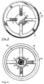
- the chassis 26 is multi-spoked. It comprises an outer flange 40 which is annular in shape and has a bevelled outermost edge 42. The outer flange is dimensioned to allow minimal protrusion of the spokes beyond the panel into which the loudspeaker is mounted. Extending inwards from the outer flange 40 are a plurality of spokes 44, which spokes terminate at a central core 46, which core 46 is generally conical in shape.
- Central core 46 has a recess 28 formed therein for accommodating a boss 30 of a magnet 12. It also has formed therein an aperture 36 for receiving a bolt 32.
- the underside 48 of the chassis has a plurality of steps and grooves therein for the attachment of various software components thereto.
- a glueing land or first face 38 accommodates a front suspension 50 and a second face 52 may accommodate a second rear suspension 54.
- the bottom face 56 of the chassis is designed to abut the centre pole of a magnet 12.
- the chassis 26 is attached to the centre pole 14 by a bolt 32.
- the chassis 26 supports the software from inside of the cone 58.
- This is in turn attached to the cone 58 which extends down to and is attached to the rear suspension 24, which is in turn fitted to the front plate 22 via a suspension support 60.
- Attached where the rear suspension 24 and cone 58 meet is a coil 62 which extends downwards into the gap 20.
- the chassis is able to provide protection to the cone. Furthermore, since the magnet is supported by its centre pole with the chassis structure in front of the cone assembly, the heat produced by the voice coil is dissipated to the outside of the loudspeaker. Furthermore, by locating the magnet from its centre pole it is easy and cost effective to vary its position relative to the front glueing land, allowing a wide variation of cone heights and voice coil lengths to be achieved.
- the centre core of the chassis reduces the volume (and hence the mass) of air directly in front of the cone, an improvement at the upper end of the loudspeaker frequency response results. Additionally, the acoustic loading of the speaker can be altered by reducing the inner diameter of the outer flange.
- the single bolt attachment of the chassis to the magnet allows easy assembly of the speaker and allows easy access for altering the rear suspension sub-assembly to optimise it for given applications.
Landscapes
- Physics & Mathematics (AREA)
- Engineering & Computer Science (AREA)
- Acoustics & Sound (AREA)
- Signal Processing (AREA)
- Audible-Bandwidth Dynamoelectric Transducers Other Than Pickups (AREA)
- Diaphragms For Electromechanical Transducers (AREA)
- Organic Low-Molecular-Weight Compounds And Preparation Thereof (AREA)
Claims (13)
- Lautsprecherbaugruppe (10), umfassend einen Magnet (12), eine Membran (58) und ein Gehäuse (26), dadurch gekennzeichnet, daß sich das Gehäuse (26) vor der genannten Membran (58) befindet und daß der Raum dahinter gehäusefrei ist, von wo es den Magneten trägt, der sich hinter der genannten Membran befindet.
- Lautsprecherbaugruppe (10) nach Anspruch 1, wobei das Gehäuse (26) einen Außenflansch (40) mit Mitteln (38) zum Befestigen einer vorderen Aufhängung (50) daran und Mittel (44) aufweist, die ein Mittelelement (46) mit dem genannten Außenflansch (40) verbinden.
- Lautsprecherbaugruppe (10) nach Anspruch 2, wobei das genannte Mittel (38) zum Befestigen einer vorderen Aufhängung (50) an dem Außenflansch (40) eine erste Fläche oder Klebleiste (38) an einer Unterseite des Flansches (40) ist.
- Lautsprecherbaugruppe (10) nach Anspruch 3, wobei das Gehäuse (26) außerdem mit einem Mittel (52) zum Befestigen einer hinteren Aufhängung (54) daran versehen ist.
- Lautsprecherbaugruppe (10) nach Anspruch 4, wobei das genannte Mittel (52) zum Befestigen einer hinteren Aufhängung eine zweite Fläche oder Klebleiste an der Schnittfläche zwischen dem Verbindungsmittel (44) und dem Mittelelement (46) ist.
- Lautsprecherbaugruppe (10) nach einem der Ansprüche 2 bis 5, wobei das Verbindungsmittel (44) des Gehäuses (26) von dem Mittelelement (46) zu dem Außenflansch (40) im wesentlichen konisch verläuft.
- Lautsprecherbaugruppe (10) nach einem der Ansprüche 1 bis 6, wobei die genannte Membran (58) eine konische Form aufweist.
- Lautsprecherbaugruppe (10) nach einem der Ansprüche 1 bis 6, wobei die genannte Membran (58) die Form eines Radialringkühlers aufweist.
- Lautsprecherbaugruppe (10) nach einem der Ansprüche 2 bis 7, wobei das genannte Mittelelement (46) an einem Mittelpol (14) des genannten Magneten (12) befestigt werden kann.
- Lautsprecherbaugruppe (10) nach einem der Ansprüche 2 bis 9, wobei das genannte Mittelelement (46) mit einem Element (28) eines ineinanderpassenden Steck-/Aufnahmeteils versehen ist.
- Lautsprecherbaugruppe (10) nach einem der Ansprüche 2 bis 10, wobei das genannte Mittel (44), das das genannte Mittelelement (46) des Gehäuses (26) mit dem Außenflansch (40) verbindet, als eine Mehrzahl von Speichen (44) ausgestaltet ist.
- Lautsprecherbaugruppe (10) nach einem der Ansprüche 2 bis 10, wobei das genannte Mittel (44), das das genannte Mittelelement (46) des Gehäuses (26) mit dem genannten Außenflansch (40) verbindet, ein gelochtes Blech ist.
- Lautsprecherbaugruppe (10) nach einem der Ansprüche 1 bis 12, wobei die Lautsprecherbaugruppe (10) ein Dauermagnetspulen-Lautsprecher ist.
Applications Claiming Priority (3)
| Application Number | Priority Date | Filing Date | Title |
|---|---|---|---|
| GB898923681A GB8923681D0 (en) | 1989-10-20 | 1989-10-20 | Improvements in or relating to loudspeakers |
| GB8923681 | 1989-10-20 | ||
| PCT/GB1990/001614 WO1991006191A1 (en) | 1989-10-20 | 1990-10-19 | Improvements in or relating to loudspeakers |
Publications (2)
| Publication Number | Publication Date |
|---|---|
| EP0496802A1 EP0496802A1 (de) | 1992-08-05 |
| EP0496802B1 true EP0496802B1 (de) | 1995-08-02 |
Family
ID=10664904
Family Applications (1)
| Application Number | Title | Priority Date | Filing Date |
|---|---|---|---|
| EP90916085A Expired - Lifetime EP0496802B1 (de) | 1989-10-20 | 1990-10-19 | Kühlvorrichtung für lautsprecher |
Country Status (10)
| Country | Link |
|---|---|
| US (1) | US5475765A (de) |
| EP (1) | EP0496802B1 (de) |
| AT (1) | ATE125999T1 (de) |
| AU (1) | AU6630390A (de) |
| DE (1) | DE69021390T2 (de) |
| DK (1) | DK0496802T3 (de) |
| ES (1) | ES2077691T3 (de) |
| GB (1) | GB8923681D0 (de) |
| GR (1) | GR3017862T3 (de) |
| WO (1) | WO1991006191A1 (de) |
Families Citing this family (13)
| Publication number | Priority date | Publication date | Assignee | Title |
|---|---|---|---|---|
| KR19980032013A (ko) * | 1995-12-15 | 1998-07-25 | 모리시타요오이찌 | 진동 발생장치 |
| GB0102780D0 (en) * | 2001-02-03 | 2001-03-21 | K H Technology Corp | Loudspeaker assemblies |
| JP4604415B2 (ja) * | 2001-07-19 | 2011-01-05 | パナソニック株式会社 | スピーカ |
| US20040030676A1 (en) * | 2002-08-07 | 2004-02-12 | International Business Machines Corporation | System and method for representation independent comparison of numerical data according to user-specified criteria |
| GB2392795B (en) * | 2002-09-04 | 2006-04-19 | B & W Loudspeakers | Suspension for the voice coil of a loudspeaker drive unit |
| US7120270B2 (en) * | 2002-09-18 | 2006-10-10 | Bose Corporation | Audio device heat transferring |
| FR2955447B1 (fr) * | 2010-01-15 | 2012-08-03 | Phl Audio | Transducteur electrodynamique comprenant un guide d'ondes acoustiques assurant une dissipation thermique |
| FR2955444B1 (fr) | 2010-01-15 | 2012-08-03 | Phl Audio | Systeme de haut-parleur coaxial a chambre de compression |
| FR2955445B1 (fr) | 2010-01-15 | 2013-06-07 | Phl Audio | Transducteur electrodynamique a dome et suspension interne |
| FR2955446B1 (fr) | 2010-01-15 | 2015-06-05 | Phl Audio | Transducteur electrodynamique a dome et suspension flottante |
| EP2373056B1 (de) * | 2010-03-12 | 2013-05-15 | Harman International Industries Ltd. | Lautsprecher mit umgekehrtem Motordesign und entsprechendes Montageverfahren |
| JP6270651B2 (ja) | 2014-07-24 | 2018-01-31 | アルパイン株式会社 | スピーカ装置 |
| US10812910B2 (en) * | 2018-09-14 | 2020-10-20 | Harman International Industries, Incorporated | Inverted motor transducer with front spider |
Family Cites Families (10)
| Publication number | Priority date | Publication date | Assignee | Title |
|---|---|---|---|---|
| BE379042A (de) * | 1930-05-06 | |||
| US1820585A (en) * | 1931-02-20 | 1931-08-25 | Magnavox Co | Loud speaker |
| GB400119A (en) * | 1933-05-03 | 1933-10-19 | Royden Albert Rothermel | Improvements in and relating to moving coil loud speakers |
| US2593031A (en) * | 1948-05-01 | 1952-04-15 | Gulton Mfg Corp | Loud-speaker |
| FR1041547A (fr) * | 1951-09-05 | 1953-10-23 | Audax | Perfectionnements aux haut-parleurs |
| US3250862A (en) * | 1963-04-22 | 1966-05-10 | William L Rollins | High energy compact permanent magnet assembly for loud speakers |
| DE2607390C2 (de) * | 1976-02-24 | 1982-09-23 | Braun Ag, 6000 Frankfurt | Dynamischer Lautsprecher mit hoher Nennbelastbarkeit |
| DE2842999A1 (de) * | 1978-10-03 | 1980-04-24 | Braun Ag | Vorrichtung zur waermeableitung bei dynamischen lautsprechern |
| JPS5677197A (en) * | 1979-11-30 | 1981-06-25 | Yooka Research Kk | Note provided with world time displaying mechanism |
| GB2108355A (en) * | 1981-10-22 | 1983-05-11 | Ard Tech Ass Eng | Electro-acoustic transducer |
-
1989
- 1989-10-20 GB GB898923681A patent/GB8923681D0/en active Pending
-
1990
- 1990-10-19 WO PCT/GB1990/001614 patent/WO1991006191A1/en active IP Right Grant
- 1990-10-19 DK DK90916085.5T patent/DK0496802T3/da active
- 1990-10-19 US US08/334,844 patent/US5475765A/en not_active Expired - Lifetime
- 1990-10-19 EP EP90916085A patent/EP0496802B1/de not_active Expired - Lifetime
- 1990-10-19 AU AU66303/90A patent/AU6630390A/en not_active Abandoned
- 1990-10-19 DE DE69021390T patent/DE69021390T2/de not_active Expired - Fee Related
- 1990-10-19 ES ES90916085T patent/ES2077691T3/es not_active Expired - Lifetime
- 1990-10-19 AT AT90916085T patent/ATE125999T1/de not_active IP Right Cessation
-
1995
- 1995-10-25 GR GR950402966T patent/GR3017862T3/el unknown
Also Published As
| Publication number | Publication date |
|---|---|
| DE69021390T2 (de) | 1996-01-25 |
| DE69021390D1 (de) | 1995-09-07 |
| DK0496802T3 (da) | 1995-09-18 |
| EP0496802A1 (de) | 1992-08-05 |
| US5475765A (en) | 1995-12-12 |
| ES2077691T3 (es) | 1995-12-01 |
| GB8923681D0 (en) | 1989-12-06 |
| GR3017862T3 (en) | 1996-01-31 |
| ATE125999T1 (de) | 1995-08-15 |
| AU6630390A (en) | 1991-05-16 |
| WO1991006191A1 (en) | 1991-05-02 |
Similar Documents
| Publication | Publication Date | Title |
|---|---|---|
| EP0821861B1 (de) | Spulenpaarantrieb mit mehrzweckgehäuse | |
| US7006653B2 (en) | Compact high performance speaker | |
| EP0496802B1 (de) | Kühlvorrichtung für lautsprecher | |
| KR101958388B1 (ko) | 채널을 갖는 라우드스피커 자석 | |
| KR101880250B1 (ko) | 저 프로화일 라우드스피커 트랜스듀서용 보강 다이어프램 | |
| KR101900005B1 (ko) | 라우드스피커 자석 조립체 | |
| WO2006064725A1 (ja) | スピーカ | |
| KR101980163B1 (ko) | 저 프로화일 라우드스피커 서스펜션 시스템 | |
| JP2001103598A (ja) | スピーカ装置およびスピーカ装置用冷却装置 | |
| WO2024022489A1 (zh) | 发声装置和终端设备 | |
| CN219960840U (zh) | 一种用于多单元耳机的水平对置双动圈低音模组 | |
| JPH06233367A (ja) | バスレフ型スピーカーシステム | |
| US5987148A (en) | Driver for a horn radiator | |
| EP1329130B1 (de) | Kompakter lautsprecher mit hoher leistungsfähigkeit | |
| JPH11187484A (ja) | スピーカ | |
| CN213602816U (zh) | 一种紧凑型可组合式高音系统及组合音响 | |
| CN217037451U (zh) | 盆架组件、扬声器以及发声设备 | |
| JP3203876B2 (ja) | スピーカ | |
| JPH0832097B2 (ja) | 同軸スピ−カ | |
| WO2024000665A1 (zh) | 扬声器 | |
| JP2660306B2 (ja) | 多重チャンバ型ラウドスピーカ・システム | |
| GB2404520A (en) | Phase plug equalizer used as heat sink for loudspeaker | |
| JPS5926714Y2 (ja) | スピ−カ | |
| JPH1127772A (ja) | スピーカ | |
| JPH0733517Y2 (ja) | 電気音響変換器 |
Legal Events
| Date | Code | Title | Description |
|---|---|---|---|
| PUAI | Public reference made under article 153(3) epc to a published international application that has entered the european phase |
Free format text: ORIGINAL CODE: 0009012 |
|
| 17P | Request for examination filed |
Effective date: 19920515 |
|
| AK | Designated contracting states |
Kind code of ref document: A1 Designated state(s): AT BE CH DE DK ES FR GB GR IT LI LU NL SE |
|
| 17Q | First examination report despatched |
Effective date: 19931103 |
|
| GRAA | (expected) grant |
Free format text: ORIGINAL CODE: 0009210 |
|
| AK | Designated contracting states |
Kind code of ref document: B1 Designated state(s): AT BE CH DE DK ES FR GB GR IT LI LU NL SE |
|
| REF | Corresponds to: |
Ref document number: 125999 Country of ref document: AT Date of ref document: 19950815 Kind code of ref document: T |
|
| ITF | It: translation for a ep patent filed | ||
| REF | Corresponds to: |
Ref document number: 69021390 Country of ref document: DE Date of ref document: 19950907 |
|
| REG | Reference to a national code |
Ref country code: DK Ref legal event code: T3 |
|
| ET | Fr: translation filed | ||
| REG | Reference to a national code |
Ref country code: ES Ref legal event code: FG2A Ref document number: 2077691 Country of ref document: ES Kind code of ref document: T3 |
|
| REG | Reference to a national code |
Ref country code: GR Ref legal event code: FG4A Free format text: 3017862 |
|
| PLBE | No opposition filed within time limit |
Free format text: ORIGINAL CODE: 0009261 |
|
| STAA | Information on the status of an ep patent application or granted ep patent |
Free format text: STATUS: NO OPPOSITION FILED WITHIN TIME LIMIT |
|
| 26N | No opposition filed | ||
| REG | Reference to a national code |
Ref country code: GB Ref legal event code: IF02 |
|
| PGFP | Annual fee paid to national office [announced via postgrant information from national office to epo] |
Ref country code: FR Payment date: 20041008 Year of fee payment: 15 |
|
| PGFP | Annual fee paid to national office [announced via postgrant information from national office to epo] |
Ref country code: AT Payment date: 20041013 Year of fee payment: 15 Ref country code: GB Payment date: 20041013 Year of fee payment: 15 |
|
| PGFP | Annual fee paid to national office [announced via postgrant information from national office to epo] |
Ref country code: DK Payment date: 20041014 Year of fee payment: 15 Ref country code: DE Payment date: 20041014 Year of fee payment: 15 |
|
| PGFP | Annual fee paid to national office [announced via postgrant information from national office to epo] |
Ref country code: CH Payment date: 20041015 Year of fee payment: 15 |
|
| PGFP | Annual fee paid to national office [announced via postgrant information from national office to epo] |
Ref country code: NL Payment date: 20041024 Year of fee payment: 15 |
|
| PGFP | Annual fee paid to national office [announced via postgrant information from national office to epo] |
Ref country code: GR Payment date: 20041027 Year of fee payment: 15 Ref country code: SE Payment date: 20041027 Year of fee payment: 15 Ref country code: LU Payment date: 20041027 Year of fee payment: 15 |
|
| PGFP | Annual fee paid to national office [announced via postgrant information from national office to epo] |
Ref country code: ES Payment date: 20041116 Year of fee payment: 15 |
|
| PGFP | Annual fee paid to national office [announced via postgrant information from national office to epo] |
Ref country code: BE Payment date: 20041217 Year of fee payment: 15 |
|
| PG25 | Lapsed in a contracting state [announced via postgrant information from national office to epo] |
Ref country code: IT Free format text: LAPSE BECAUSE OF NON-PAYMENT OF DUE FEES;WARNING: LAPSES OF ITALIAN PATENTS WITH EFFECTIVE DATE BEFORE 2007 MAY HAVE OCCURRED AT ANY TIME BEFORE 2007. THE CORRECT EFFECTIVE DATE MAY BE DIFFERENT FROM THE ONE RECORDED. Effective date: 20051019 Ref country code: AT Free format text: LAPSE BECAUSE OF NON-PAYMENT OF DUE FEES Effective date: 20051019 Ref country code: GB Free format text: LAPSE BECAUSE OF NON-PAYMENT OF DUE FEES Effective date: 20051019 |
|
| PG25 | Lapsed in a contracting state [announced via postgrant information from national office to epo] |
Ref country code: ES Free format text: LAPSE BECAUSE OF NON-PAYMENT OF DUE FEES Effective date: 20051020 Ref country code: SE Free format text: LAPSE BECAUSE OF NON-PAYMENT OF DUE FEES Effective date: 20051020 |
|
| PG25 | Lapsed in a contracting state [announced via postgrant information from national office to epo] |
Ref country code: DK Free format text: LAPSE BECAUSE OF NON-PAYMENT OF DUE FEES Effective date: 20051031 Ref country code: LI Free format text: LAPSE BECAUSE OF NON-PAYMENT OF DUE FEES Effective date: 20051031 Ref country code: LU Free format text: LAPSE BECAUSE OF NON-PAYMENT OF DUE FEES Effective date: 20051031 Ref country code: CH Free format text: LAPSE BECAUSE OF NON-PAYMENT OF DUE FEES Effective date: 20051031 Ref country code: BE Free format text: LAPSE BECAUSE OF NON-PAYMENT OF DUE FEES Effective date: 20051031 |
|
| PG25 | Lapsed in a contracting state [announced via postgrant information from national office to epo] |
Ref country code: NL Free format text: LAPSE BECAUSE OF NON-PAYMENT OF DUE FEES Effective date: 20060501 |
|
| PG25 | Lapsed in a contracting state [announced via postgrant information from national office to epo] |
Ref country code: DE Free format text: LAPSE BECAUSE OF NON-PAYMENT OF DUE FEES Effective date: 20060503 |
|
| REG | Reference to a national code |
Ref country code: DK Ref legal event code: EBP |
|
| REG | Reference to a national code |
Ref country code: CH Ref legal event code: PL |
|
| EUG | Se: european patent has lapsed | ||
| GBPC | Gb: european patent ceased through non-payment of renewal fee |
Effective date: 20051019 |
|
| PG25 | Lapsed in a contracting state [announced via postgrant information from national office to epo] |
Ref country code: FR Free format text: LAPSE BECAUSE OF NON-PAYMENT OF DUE FEES Effective date: 20060630 |
|
| NLV4 | Nl: lapsed or anulled due to non-payment of the annual fee |
Effective date: 20060501 |
|
| REG | Reference to a national code |
Ref country code: FR Ref legal event code: ST Effective date: 20060630 |
|
| REG | Reference to a national code |
Ref country code: ES Ref legal event code: FD2A Effective date: 20051020 |
|
| BERE | Be: lapsed |
Owner name: *LYTH CHARLES DAVID Effective date: 20051031 |
|
| PG25 | Lapsed in a contracting state [announced via postgrant information from national office to epo] |
Ref country code: GR Free format text: LAPSE BECAUSE OF NON-PAYMENT OF DUE FEES Effective date: 19950802 |