EP0496103A2 - Sanitärarmatur mit Schwenkauslauf - Google Patents
Sanitärarmatur mit Schwenkauslauf Download PDFInfo
- Publication number
- EP0496103A2 EP0496103A2 EP91122087A EP91122087A EP0496103A2 EP 0496103 A2 EP0496103 A2 EP 0496103A2 EP 91122087 A EP91122087 A EP 91122087A EP 91122087 A EP91122087 A EP 91122087A EP 0496103 A2 EP0496103 A2 EP 0496103A2
- Authority
- EP
- European Patent Office
- Prior art keywords
- spout
- swivel spout
- swivel
- guide ring
- sanitary fitting
- Prior art date
- Legal status (The legal status is an assumption and is not a legal conclusion. Google has not performed a legal analysis and makes no representation as to the accuracy of the status listed.)
- Granted
Links
Images

Classifications
-
- E—FIXED CONSTRUCTIONS
- E03—WATER SUPPLY; SEWERAGE
- E03C—DOMESTIC PLUMBING INSTALLATIONS FOR FRESH WATER OR WASTE WATER; SINKS
- E03C1/00—Domestic plumbing installations for fresh water or waste water; Sinks
- E03C1/02—Plumbing installations for fresh water
- E03C1/04—Water-basin installations specially adapted to wash-basins or baths
- E03C1/0404—Constructional or functional features of the spout
-
- F—MECHANICAL ENGINEERING; LIGHTING; HEATING; WEAPONS; BLASTING
- F16—ENGINEERING ELEMENTS AND UNITS; GENERAL MEASURES FOR PRODUCING AND MAINTAINING EFFECTIVE FUNCTIONING OF MACHINES OR INSTALLATIONS; THERMAL INSULATION IN GENERAL
- F16L—PIPES; JOINTS OR FITTINGS FOR PIPES; SUPPORTS FOR PIPES, CABLES OR PROTECTIVE TUBING; MEANS FOR THERMAL INSULATION IN GENERAL
- F16L27/00—Adjustable joints, Joints allowing movement
- F16L27/08—Adjustable joints, Joints allowing movement allowing adjustment or movement only about the axis of one pipe
- F16L27/0804—Adjustable joints, Joints allowing movement allowing adjustment or movement only about the axis of one pipe the fluid passing axially from one joint element to another
- F16L27/0808—Adjustable joints, Joints allowing movement allowing adjustment or movement only about the axis of one pipe the fluid passing axially from one joint element to another the joint elements extending coaxially for some distance from their point of separation
- F16L27/0812—Adjustable joints, Joints allowing movement allowing adjustment or movement only about the axis of one pipe the fluid passing axially from one joint element to another the joint elements extending coaxially for some distance from their point of separation with slide bearings
- F16L27/0816—Adjustable joints, Joints allowing movement allowing adjustment or movement only about the axis of one pipe the fluid passing axially from one joint element to another the joint elements extending coaxially for some distance from their point of separation with slide bearings having radial sealing
-
- E—FIXED CONSTRUCTIONS
- E03—WATER SUPPLY; SEWERAGE
- E03C—DOMESTIC PLUMBING INSTALLATIONS FOR FRESH WATER OR WASTE WATER; SINKS
- E03C1/00—Domestic plumbing installations for fresh water or waste water; Sinks
- E03C1/02—Plumbing installations for fresh water
- E03C1/04—Water-basin installations specially adapted to wash-basins or baths
- E03C2001/0414—Water-basin installations specially adapted to wash-basins or baths allowing different orientations of the spout or the outlet nozzle
Definitions
- the material elevations can be axially extending ribs; alternatively, these can also be discrete knobs.
- An embodiment of the invention is particularly advantageous in which a guide ring carrying material elevations is simultaneously designed as a stop ring for limiting the pivoting angle of the pivoting outlet. Because the guide ring now also takes on a second task, namely that of limiting the swivel angle, the number of components required on the sanitary fitting is kept small. The play-free mounting of the swivel spout on the guide ring, which is achieved with the present invention, also benefits the swivel angle limitation in this way.
- the upper end of the fitting housing of a sanitary fitting is identified by the reference number 1.
- the precise structure of this sanitary fitting is of no importance in the present context. In particular, it does not matter whether the outflowing water is mixed water or pure cold or hot water; it is also irrelevant whether the sanitary fitting contains the controlling shut-off elements themselves or whether it is a pure one Faucet outlet acts.
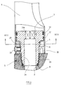
- the valve housing 1 is penetrated by an axial water channel 2 which widens in the upper area to a threaded opening 2a. From above, a receptacle 3 is screwed into the threaded opening 2a, to which a swivel spout 4 is pivotally attached in the manner described below.
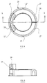
- the receptacle 3 is shown in isolation in FIGS. 2 and 3. This is referred to first.
- the receptacle 3 can be roughly divided into an upper region of larger diameter 3a and a lower region of smaller diameter 3b, at the transition of which an annular shoulder 5 pointing downward is formed.
- the lower area 3b of smaller diameter carries the screw-in thread 6, which cooperates with the threaded opening 2a of the valve body 1.
- a step 7 At the lowest end of the receptacle 3 there is a step 7, in which (see FIG. 1) an O-ring 8 is inserted, which serves to seal between the receptacle 3 and the fitting housing 1.
- the upper area 3a of larger diameter of the receptacle 3 is provided with two grooves 10, 11.
- the lower groove 10 receives a guide ring 12 (cf. FIG. 1), while an O-ring 13 (also shown in FIG. 1) lies in the upper groove 11.
- the entire receptacle 3 is traversed by a channel 14, which continues the water channel 2 in the fitting housing 1 and is designed in the upper region as a polygonal region 14a.
- a correspondingly shaped tool can be attached to the polygonal region 14a of the channel 14 when the receptacle 3 is screwed into the fitting housing 1.
- the swivel spout 4 is pushed over the receptacle 3 screwed into the fitting housing 1 in such a way that the inner circumferential surface of its wall lies against both the O-ring 13 and the guide ring 12.
- a stop ring 15 is used, which serves several functions in a manner to be described.
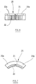
- the stop ring 15 is shown in more detail in FIGS. 4 and 5, to which reference is now made.
- the stop ring 15 as can be seen in particular in FIG. 4, is slotted at 16, so that it can resiliently bear against the region 3b of the receptacle 3. At regular intervals, it carries radially protruding, axially parallel ribs 17 on the outer lateral surface. These are areas of material which are plastically deformed, namely compressed, when the inner lateral surface of the swivel spout 4 is pushed over them. The ribs 17 thus serve to compensate for tolerances between the inside dimension of the swivel spout 4 and the stop ring 15.
- the stop ring 15 is formed in a certain angular range with an arc-shaped, axially projecting stop projection 18, which with its upper end face on the ring shoulder 5 and with the upper end of its inner Shell surface abuts an outer cylindrical shell surface of the receptacle 3. In this way, the stop ring 15 ensures play-free radial mounting and axial securing of the swivel spout 4 on the receptacle 3. He is supported by the guide ring 12, on the outer lateral surface of which similar plastically deformable ribs are provided, as have already been described above with the reference number 17 on the stop ring 15.
- FIG. 1 shows, the swivel spout 4 placed over the receptacle 3 is fastened to the stop ring 15 by means of a screw 19.
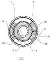
- the stop ring 15 takes on the function of limiting the angle of rotation of the swivel spout 4 in addition to the mounting and mounting of the swivel spout 4 , the receptacle 3 and the inner circumferential surface of the swivel spout 4 limited annular space is plugged onto the toothing 9.
- the spatial relationships are particularly clear when considering FIGS. 1 and 8.
- Figures 6 and 7 show the stop piece 20 for itself. It can be seen particularly clearly from these figures that the stop piece 20 is composed of two parts 20a and 20b which are connected to one another via a predetermined breaking point 21.
- the stop piece 20 has on its inner circumferential surface a toothing 22 which is complementary to the external toothing 9 on the receptacle 3.
- the swivel spout 4 can be rotated by the maximum swivel angle; the pivoting movement comes to an end when the stop projection 18 of the stop ring 15 abuts against one of the two parts 20a or 20b of the stop piece 20.
- the maximum swivel angle of the swivel spout 4 is calculated as the difference between 360 ° and the sum of the two angles which are enclosed by the stop piece 20 and the stop projection 18.
- the swivel spout 4 can also be fixed non-rotatably in any angular position.
- the two parts 20a and 20b of the stop piece 20 are detached from one another at the predetermined breaking point 21. They are then placed separately on the toothing 9 of the receptacle 3 so that they enclose the stop projection 18 in the correct angular position and in direct contact between them. The angular movement of the stop projection 18 and thus of the swivel spout 4 is then prevented in both directions by a part 20a, 20b of the stop piece 20.
- any conceivable intermediate state between a complete fixation of the swivel spout 4 and its maximum rotatability can be selected by a suitable choice of the angular position in which the parts 20a or 20b are fitted onto the toothing 9.
- swivel spouts of the type of interest here for example due to the overall fitting on which they are located, a middle position.
Abstract
Description
- Die Erfindung betrifft eine Sanitärarmatur mit Schwenkauslauf mit
- a) einem Armaturengehäuse, auf welches der Schwenkauslauf verschwenkbar aufsteckbar ist;
- b) mindestens einem als Radiallager dienenden Führungsring zwischen dem Schwenkauslauf und dem Armaturengehäuse bzw. einem mit diesem verbundenen Teil;
- c) einer Einrichtung an dem Führungsring, welche zur spielfreien Radiallagerung des Schwenkauslaufes unterschiedliche Toleranzen auszugleichen vermag.
Eine derartige Sanitärarmatur ist aus der DE-PS 29 48 474 bekannt. Die Radiallagerung des in das Armaturengehäuse einsteckbaren Schwenkauslaufes wird hier von zwei Führungsringen besorgt, die in axialem Abstand voneinander angeordnet sind. Damit diese Lagerung spielfrei ist, ist jeder Führungsring mit aufspreizbaren, elastischen Federsegmenten gestaltet, die beim Einschieben des Schwenkauslaufes in die Aufnahme des Armaturengehäuses elastisch komprimiert werden. Diese elastischen Federsegmente entspannen sich beim Herausziehen des Schwenkauslaufes wieder. Derartige elastische Federsegmente aufweisende Führungsringe sind jedoch verhältnismäßig komplizierte Bauteile.
Aufgabe der vorliegenden Erfindung ist es, eine Sanitärarmatur der eingangs genannten Art so auszugestalten, daß die spielfreie Lagerung mit einfacheren Mitteln erzielt wird.
Diese Aufgabe wird erfindungsgemäß dadurch gelöst, daß - d) die Einrichtung am Führungsring Materialerhebungen an einer Mantelfläche umfaßt, die beim Aufstecken des Schwenkauslaufes plastisch deformierbar sind.
- Erfindungsgemäß werden also zum Toleranzausgleich keine elastischen Federelemente sondern plastisch deformierbare Materialbereiche eingesetzt, die praktisch kostenfrei bei der Herstellung der Führungsringe mit angeformt werden können. Erfindungsgemäße Führungsringe sind also nicht teurer als konventionelle Radiallagerringe mit glatten, konzentrischen Mantelflächen.
- Die Materialerhebungen können axial verlaufende Rippen sein; es kann sich alternativ hierbei auch um diskrete Noppen handeln.
- Besonders vorteilhaft ist eine Ausgestaltung der Erfindung, bei welcher ein Materialerhebungen tragender Führungsring gleichzeitig als Anschlagring zur Begrenzung des Schwenkwinkels des Schwenkauslaufes ausgebildet ist. Dadurch, daß der Führungsring nunmehr auch eine zweite Aufgabe, nämlich diejenige der Begrenzung des Schwenkwinkels, übernimmt, wird die Anzahl der insgesamt erforderlichen Bauelemente an der Sanitärarmatur kleingehalten. Die spielfreie Lagerung des Schwenkauslaufes an dem Führungsring, die mit der vorliegenden Erfindung erzielt wird, kommt auf diese Weise auch der Schwenkwinkelbegrenzung zugute.
- Die Vorteile der erfindungsgemäßen Ausgestaltung einer Sanitärarmatur kommen besonders dann zur Geltung, wenn in axialem Abstand voneinander zwei oder mehr Führungsringe mit Materialerhebungen an einer Mantelfläche vorgesehen sind.
- Ein Ausführungsbeispiel der Erfindung wird nachfolgend anhand der Zeichnung näher erläutert; es zeigen
- Figur 1:
- einen axialen Teilschnitt durch eine Sanitärarmatur mit Schwenkauslauf;
- Figur 2:
- die Seitenansicht der Auslauf-Aufnahme der in Figur 1 dargestellten Sanitärarmatur, in der rechten Hälfte geschnitten;
- Figur 3:
- einen Schnitt gemäß Linie III-III von Figur 2;
- Figur 4:
- die Draufsicht auf einen Anschlagring der in Figur 1 dargestellten Sanitärarmatur;
- Figur 5:
- einen Schnitt gemäß Linie V-V von Figur 4;
- Figur 6:
- die Seitenansicht eines Anschlagstückes aus der Sanitärarmatur von Figur 1;
- Figur 7:
- die Draufsicht auf das Anschlagstück von Figur 6;
- Figur 8:
- einen Schnitt gemäß Linie VIII-VIII von Figur 1.
- In Figur 1 ist das obere Ende des Armaturengehäuses einer Sanitärarmatur mit dem Bezugszeichen 1 gekennzeichnet. Der genauere Aufbau dieser Sanitärarmatur ist im vorliegenden Zusammenhang ohne Bedeutung. Insbesondere kommt es also nicht darauf an, ob das ausfließende Wasser Mischwasser oder reines Kalt- bzw. Warmwasser ist; ebenso ist es irrelevant, ob die Sanitärarmatur die steuernden Absperrelemente selbst enthält oder ob es sich um einen reinen Armaturenauslauf handelt.
- Das Armaturengehäuse 1 wird von einem axialen Wasserkanal 2 durchsetzt, der sich im oberen Bereich zu einer Gewindeöffnung 2a erweitert. In die Gewindeöffnung 2a ist von oben eine Aufnahme 3 eingeschraubt, an welcher in weiter unten beschriebener Weise ein Schwenkauslauf 4 verschwenkbar befestigt ist.
- Die Aufnahme 3 ist in den Figuren 2 und 3 isoliert dargestellt. Hierauf wird zunächst Bezug genommen.
- Die Aufnahme 3 läßt sich grob in einen oberen Bereich größeren Durchmessers 3a und einen unteren Bereich kleineren Durchmessers 3b unterteilen, an deren Übergang eine nach unten zeigende Ringschulter 5 gebildet ist. Der untere Bereich 3b kleineren Durchmessers trägt das Einschraubgewinde 6, welches mit der Gewindeöffnung 2a des Armaturengehäuses 1 zusammenwirkt. An untersten Ende der Aufnahme 3 befindet sich eine Stufe 7, in welche (vergl. Figur 1) ein O-Ring 8 eingelegt ist, welcher der Abdichtung zwischen der Aufnahme 3 und den Armaturengehäuse 1 dient.
- Oberhalb des Einschraubgewindes 6, in der Nähe der Ringschulter 5, trägt der untere Bereich 3b der Aufnahme 3 eine Verzahnung 9, auf deren Sinn weiter unten eingegangen wird.
- Der obere Bereich 3a größeren Durchmessers der Aufnahme 3 ist mit zwei Nuten 10, 11 versehen. Die untere Nut 10 nimmt einen Führungsring 12 (vergl. Figur 1) auf, während in der oberen Nut 11 ein O-Ring 13 (ebenfalls in Figur 1 zu erkennen) einliegt.
- Die gesamte Aufnahme 3 wird von einem Kanal 14 durchzogen, welcher den Wasserkanal 2 im Armaturengehäuse 1 fortsetzt und im oberen Bereich als Mehrkantbereich 14a ausgebildet ist. An dem Mehrkantbereich 14a des Kanals 14 kann beim Eindrehen der Aufnahme 3 in das Armaturengehäuse 1 ein entsprechend geformtes Werkzeug ansetzen.
- Der Schwenkauslauf 4 wird, wie in Figur 1 gezeigt, über die in das Armaturengehäuse 1 eingedrehte Aufnahme 3 so geschoben, daß die innere Mantelfläche seiner Wand sowohl an dem O-Ring 13 als auch an dem Führungsring 12 anliegt.
- In dem Ringraum, der sich zwischen dem unteren Bereich des Schwenkauslaufes 4 und dem Bereich 3b engeren Durchmessers der Aufnahme 3 unterhalb der Ringschulter 5 ergibt, ist ein Anschlagring 15 eingesetzt, welcher in noch zu beschreibender Weise mehreren Funktionen dient. Der Anschlagring 15 ist in den Figuren 4 und 5 näher dargestellt, auf welche nunmehr Bezug genommen wird.
- Der Anschlagring 15 ist, wie insbesondere der Figur 4 zu entnehmen ist, bei 16 geschlitzt, so daß er sich elastisch federnd gegen den Bereich 3b der Aufnahme 3 anlegen kann. Auf der äußeren Mantelfläche trägt er in regelmäßigen Abständen radial vorstehende, achsparallele Rippen 17. Dabei handelt es sich um Materialbereiche, die plastisch verformt, nämlich zusammengedrückt werden, wenn die Innenmantelfläche des Schwenkauslaufes 4 über sie geschoben wird. Die Rippen 17 dienen so zum Toleranzausgleich zwischen dem Innenmaß des Schwenkauslaufes 4 und dem Anschlagring 15.
- Der Anschlagring 15 ist in einem bestimmten Winkelbereich mit einem bogenförmigen, axial überstehenden Anschlagvorsprung 18 ausgebildet, der mit seiner oberen Stirnfläche an der Ringschulter 5 und mit dem oberen Ende seiner inneren Mantelfläche an einer äußeren zylindrischen Mantelfläche der Aufnahme 3 anliegt. Auf diese Weise stellt der Anschlagring 15 eine spielfreie Radiallagerung und Axialsicherung des Schwenkauslaufes 4 an der Aufnahme 3 sicher. Er wird dabei von dem Führungsring 12 unterstützt, an dessen äußerer Mantelfläche ähnliche plastisch verformbare Rippen vorgesehen sind, wie sie oben mit dem Bezugszeichen 17 an dem Anschlagring 15 bereits beschrieben wurden.
- Wie Figur 1 zeigt, ist der über die Aufnahme 3 gestülpte Schwenkauslauf 4 mittels einer Schraube 19 an dem Anschlagring 15 befestigt.
- Der Anschlagring 15 übernimmt, wie sein Name sagt, neben der Lagerung und Halterung des Schwenkauslaufes 4 die Funktion einer Begrenzung des Drehwinkels des Schwenkauslaufes 4. Sein Anschlagvorsprung 18 wirkt hierbei als erstes Anschlagstück mit einem zweiten Anschlagstück 20 zusammen, welches in dem von den Anschlagring 15, der Aufnahme 3 und der Innenmantelfläche des Schwenkauslaufes 4 begrenzten Ringraum auf der Verzahnung 9 aufgesteckt ist. Die räumlichen Verhältnisse werden insbesondere bei der Betrachtung der Figuren 1 und 8 deutlich.
- Die Figuren 6 und 7 zeigen das Anschlagstück 20 für sich. Diesen Figuren ist besonders deutlich zu entnehmen, daß das Anschlagstück 20 aus zwei Teilen 20a und 20b zusammengesetzt ist, die über eine Sollbruchstelle 21 miteinander verbunden sind. Das Anschlagstück 20 trägt an seiner Innenmantelfläche eine Verzahnung 22, welche zu der Außenverzahnung 9 an der Aufnahme 3 komplementär ist.
- Die Art des Zusammenwirkens zwischen dem Anschlagvorsprung 18 des Anschlagringes 15 (der gemeinsam mit den Schwenkauslauf 4 verdreht wird) und den Anschlagstück 20 (welches unverdrehbar auf die Verzahnung 9 der Aufnahme 3 aufgesteckt ist) ist wie folgt:
- Befinden sich die beiden Teile 20a und 20b des Anschlagstückes 20, wie in Figur 8 dargestellt, in unmittelbarer Nachbarschaft, ist insbesondere also die Sollbruchstelle 21 noch nicht gelöst, dann läßt sich der Schwenkauslauf 4 um den maximalen Schwenkwinkel verdrehen; die Schwenkbewegung findet ja dann ihr Ende, wenn der Anschlagvorsprung 18 des Anschlagringes 15 gegen eines der beiden Teile 20a oder 20b des Anschlagstückes 20 anstößt. Der maximale Schwenkwinkel des Schwenkauslaufes 4 errechnet sich dabei als Differenz zwischen 360° und der Summe der beiden Winkel, die von dem Anschlagstück 20 und dem Anschlagvorsprung 18 eingeschlossen werden.
- Mit Hilfe des Anschlagstückes 20 kann aber der Schwenkauslauf 4 auch in jeder beliebigen Winkelposition unverdrehbar fixiert werden. Hierzu werden die beiden Teile 20a und 20b des Anschlagstückes 20 an der Sollbruchstelle 21 voneinander gelöst. Sie werden dann getrennt so auf die Verzahnung 9 der Aufnahme 3 aufgesteckt, daß sie den Anschlagvorsprung 18 in der richtigen Winkelposition und in unmittelbarer Anlage zwischen sich einschließen. Die Winkelbewegung des Anschlagvorsprunges 18 und damit des Schwenkauslaufes 4 ist dann in beiden Richtungen jeweils durch ein Teil 20a, 20b des Anschlagstückes 20 unterbunden.
- Selbstverständlich läßt sich durch geeignete Wahl der Winkelposition, in welcher die Teile 20a oder 20b auf die Verzahnung 9 aufgesteckt werden, jeder denkbare Zwischenzustand zwischen einer vollständigen Fixierung des Schwenkauslaufes 4 und dessen maximaler Verdrehbarkeit wählen. Schwenkausläufe der hier interessierenden Art haben aus äußeren geometrischen Gründen, beispielsweise aufgrund der Gesamtarmatur, an der sie sich befinden, eine Mittelstellung. Durch die Zweiteilung des Anschlagstückes 20 ist es offensichtlich möglich, Drehwinkelbeschränkungen des Schwenkauslaufes 4 nicht nur symmetrisch zu dieser Mittelstellung sondern ganz nach Wunsch auch asymmetrisch vorzunehmen.
Claims (5)
- Sanitärarmatur mit Schwenkauslauf mita) einem Armaturengehäuse, auf welches der Schwenkauslauf verschwenkbar aufsteckbar ist;b) mindestens einem als Radiallager dienenden Führungsring zwischen dem Schwenkauslauf und dem Armaturengehäuse bzw. einem mit diesem verbundenen Teil;c) einer Einrichtung an dem Führungsring, welche zur spielfreien Radiallagerung des Schwenkauslaufes unterschiedliche Toleranzen auszugleichen vermag,
dadurch gekennzeichnet, daß
d) die Einrichtung am Führungsring (15, 12) Materialerhebungen (17) an einer Mantelfläche umfasst, die beim Aufstecken des Schwenkauslaufes (4) plastisch deformierbar sind. - Sanitärarmatur nach Anspruch 1, dadurch gekennzeichnet, daß die Materialerhebungen axial verlaufende Rippen (17) sind.
- Sanitärarmatur nach Anspruch 1, dadurch gekennzeichnet, daß die Materialerhebungen diskrete Noppen sind.
- Sanitärarmatur nach einem der vorhergehenden Ansprüche, dadurch gekennzeichnet, daß ein Materialerhebungen (17) tragender Führungsring (15) gleichzeitig als Anschlagring zur Begrenzung des Schwenkwinkels des Schwenkauslaufes (4) ausgebildet ist.
- Sanitärarmatur nach einem der vorhergehenden Ansprüche, dadurch gekennzeichnet, daß in axialen Abstand voneinander zwei oder mehr Führungsringe (15, 12) mit Materialerhebungen (17) an einer Mantelfläche vorgesehen sind.
Applications Claiming Priority (2)
| Application Number | Priority Date | Filing Date | Title |
|---|---|---|---|
| DE4102133 | 1991-01-25 | ||
| DE4102133A DE4102133C2 (de) | 1991-01-25 | 1991-01-25 | Sanitärarmatur mit Schwenkauslauf |
Publications (3)
| Publication Number | Publication Date |
|---|---|
| EP0496103A2 true EP0496103A2 (de) | 1992-07-29 |
| EP0496103A3 EP0496103A3 (en) | 1992-11-25 |
| EP0496103B1 EP0496103B1 (de) | 1997-03-26 |
Family
ID=6423660
Family Applications (1)
| Application Number | Title | Priority Date | Filing Date |
|---|---|---|---|
| EP91122087A Expired - Lifetime EP0496103B1 (de) | 1991-01-25 | 1991-12-22 | Sanitärarmatur mit Schwenkauslauf |
Country Status (4)
| Country | Link |
|---|---|
| EP (1) | EP0496103B1 (de) |
| AT (1) | ATE150856T1 (de) |
| DE (1) | DE4102133C2 (de) |
| ES (1) | ES2100201T3 (de) |
Cited By (3)
| Publication number | Priority date | Publication date | Assignee | Title |
|---|---|---|---|---|
| EP0730911A1 (de) * | 1995-03-10 | 1996-09-11 | Hansa Metallwerke Ag | Handbrause |
| EP1507044A3 (de) * | 2003-08-13 | 2008-04-09 | Hansa Metallwerke Ag | Sanitärarmatur mit Schwenkauslauf |
| CN107830217A (zh) * | 2017-10-16 | 2018-03-23 | 宁波欧琳厨具有限公司 | 水龙头 |
Families Citing this family (2)
| Publication number | Priority date | Publication date | Assignee | Title |
|---|---|---|---|---|
| DE19941820C1 (de) * | 1999-09-02 | 2001-02-08 | Hansa Metallwerke Ag | Sanitärarmatur |
| DE102013011708A1 (de) * | 2013-07-15 | 2015-01-15 | Hansa Metallwerke Ag | Radiallager-Ringelement und Sanitärarmatur mit einem solchen |
Citations (3)
| Publication number | Priority date | Publication date | Assignee | Title |
|---|---|---|---|---|
| DE2629795A1 (de) * | 1976-07-02 | 1978-01-05 | Hansa Metallwerke Ag | In einem ventilauslaufstutzen schwenkbar gelagertes auslaufrohr |
| DE2948474C2 (de) * | 1979-12-01 | 1983-11-17 | Friedrich Grohe Armaturenfabrik Gmbh & Co, 5870 Hemer | Sanitärarmatur mit schwenkbarem Auslaufarm |
| DE3815492A1 (de) * | 1988-05-06 | 1989-11-16 | Hackforth Gmbh & Co Kg | Verbindungssystem fuer ein zylindrisches metallisches rohr |
Family Cites Families (2)
| Publication number | Priority date | Publication date | Assignee | Title |
|---|---|---|---|---|
| DE2853052C2 (de) * | 1978-12-08 | 1982-10-07 | Hansa Metallwerke Ag, 7000 Stuttgart | Steuerkartusche für ein Ventil |
| DE3509310A1 (de) * | 1985-03-15 | 1986-09-18 | Hans Grohe Gmbh & Co Kg, 7622 Schiltach | Schwenkrohrauslauf fuer armaturen |
-
1991
- 1991-01-25 DE DE4102133A patent/DE4102133C2/de not_active Expired - Fee Related
- 1991-12-22 AT AT91122087T patent/ATE150856T1/de not_active IP Right Cessation
- 1991-12-22 ES ES91122087T patent/ES2100201T3/es not_active Expired - Lifetime
- 1991-12-22 EP EP91122087A patent/EP0496103B1/de not_active Expired - Lifetime
Patent Citations (3)
| Publication number | Priority date | Publication date | Assignee | Title |
|---|---|---|---|---|
| DE2629795A1 (de) * | 1976-07-02 | 1978-01-05 | Hansa Metallwerke Ag | In einem ventilauslaufstutzen schwenkbar gelagertes auslaufrohr |
| DE2948474C2 (de) * | 1979-12-01 | 1983-11-17 | Friedrich Grohe Armaturenfabrik Gmbh & Co, 5870 Hemer | Sanitärarmatur mit schwenkbarem Auslaufarm |
| DE3815492A1 (de) * | 1988-05-06 | 1989-11-16 | Hackforth Gmbh & Co Kg | Verbindungssystem fuer ein zylindrisches metallisches rohr |
Cited By (3)
| Publication number | Priority date | Publication date | Assignee | Title |
|---|---|---|---|---|
| EP0730911A1 (de) * | 1995-03-10 | 1996-09-11 | Hansa Metallwerke Ag | Handbrause |
| EP1507044A3 (de) * | 2003-08-13 | 2008-04-09 | Hansa Metallwerke Ag | Sanitärarmatur mit Schwenkauslauf |
| CN107830217A (zh) * | 2017-10-16 | 2018-03-23 | 宁波欧琳厨具有限公司 | 水龙头 |
Also Published As
| Publication number | Publication date |
|---|---|
| EP0496103B1 (de) | 1997-03-26 |
| DE4102133C2 (de) | 1997-08-21 |
| EP0496103A3 (en) | 1992-11-25 |
| DE4102133A1 (de) | 1992-07-30 |
| ES2100201T3 (es) | 1997-06-16 |
| ATE150856T1 (de) | 1997-04-15 |
Similar Documents
| Publication | Publication Date | Title |
|---|---|---|
| EP1501453B2 (de) | Höhenverstellbares implantat zum einsetzen zwischen wirbelkörpern und handhabungswerkzeug | |
| DE2038767C3 (de) | Schraubkupplung zum Befestigen eines Objektivs an einer Kamera | |
| DE19637074A1 (de) | Kupplungseinrichtung zur Verbindung zweier Rohrelemente | |
| DE3843095C2 (de) | Befestigungseinrichtung für Verkleidungen | |
| DE4222759A1 (de) | Kosmetikstift mit Austauschteil | |
| EP0414002B1 (de) | Lötwerkzeug | |
| EP3428353A1 (de) | Wandhalterung für einen sanitärartikel | |
| EP0530471A1 (de) | Stellvorrichtung für ein Mischventil | |
| EP0044904A2 (de) | Thermostat zur Regelung eines Heizkörperventils | |
| DE3906959C1 (en) | Assembly device for automotive gear clutches | |
| EP0496103B1 (de) | Sanitärarmatur mit Schwenkauslauf | |
| EP0683931B1 (de) | Befehls- und/oder meldegerät | |
| DE3300623A1 (de) | Ventil, insbesondere thermostatventil fuer warmwasserheizkoerper | |
| DE2823561A1 (de) | Messinstrument | |
| EP0683341A2 (de) | Sanitärarmatur | |
| DE3625287A1 (de) | Teleskopstiel | |
| EP0955479B1 (de) | Vorrichtung zum Verbinden von Bauteilen | |
| DE4338495C1 (de) | Vorrichtung zum Verbinden eines Rades mit einer Radachse | |
| EP0303127A1 (de) | Einrichtung mit einem Schraubelement und einem Mutterelement, und Verwendung der Einrichtung | |
| DE4102132C1 (en) | Dewatering device partic for sludge of paper fibres - has system of horizontally dewatering rotating drum with screen form conveyor belt and pressure belt passing around drum at specific angle AB DE4101856C Sludge, partic. of paper fibres, is dewatered in an arrangement of a horizontally rotating dewatering drum (2) with a conveyor belt (3) in the form of a screen and a pressure belt (4), which pass round the drum with an arc of contact of 180 deg. max. Inlet (5) and outlet (6) drums are connected to the dewatering drum, the belts passing under these drums and over the dewatering drum, which is enclosed by a jacket with drainage channels. ADVANTAGE - Continuous dewatering with high efficiency is obtd.. AN 92235346 TI Sanitary fitting with swivelable outlet - has two stops, one with rated break point for separation into two independent parts | |
| DE3506121C2 (de) | ||
| DE4035707C2 (de) | Einstellmechanismus für ein Fernglas | |
| DE2344621A1 (de) | Vorrichtung zum aufschrauben einer mutter mit innengewinde auf ein mit einem aussengewinde versehenes glied | |
| EP4012200B1 (de) | Federbelasteter rastbolzen | |
| EP0730911A1 (de) | Handbrause |
Legal Events
| Date | Code | Title | Description |
|---|---|---|---|
| PUAI | Public reference made under article 153(3) epc to a published international application that has entered the european phase |
Free format text: ORIGINAL CODE: 0009012 |
|
| AK | Designated contracting states |
Kind code of ref document: A2 Designated state(s): AT CH ES FR GB IT LI |
|
| PUAL | Search report despatched |
Free format text: ORIGINAL CODE: 0009013 |
|
| AK | Designated contracting states |
Kind code of ref document: A3 Designated state(s): AT CH ES FR GB IT LI |
|
| 17P | Request for examination filed |
Effective date: 19930511 |
|
| 17Q | First examination report despatched |
Effective date: 19950111 |
|
| GRAG | Despatch of communication of intention to grant |
Free format text: ORIGINAL CODE: EPIDOS AGRA |
|
| GRAH | Despatch of communication of intention to grant a patent |
Free format text: ORIGINAL CODE: EPIDOS IGRA |
|
| GRAH | Despatch of communication of intention to grant a patent |
Free format text: ORIGINAL CODE: EPIDOS IGRA |
|
| GRAA | (expected) grant |
Free format text: ORIGINAL CODE: 0009210 |
|
| AK | Designated contracting states |
Kind code of ref document: B1 Designated state(s): AT CH ES FR GB IT LI |
|
| REF | Corresponds to: |
Ref document number: 150856 Country of ref document: AT Date of ref document: 19970415 Kind code of ref document: T |
|
| REG | Reference to a national code |
Ref country code: CH Ref legal event code: EP |
|
| REG | Reference to a national code |
Ref country code: CH Ref legal event code: NV Representative=s name: FREI PATENTANWALTSBUERO |
|
| ET | Fr: translation filed | ||
| ITF | It: translation for a ep patent filed |
Owner name: STUDIO JAUMANN |
|
| REG | Reference to a national code |
Ref country code: CH Ref legal event code: NV Representative=s name: FREI PATENTANWALTSBUERO |
|
| REG | Reference to a national code |
Ref country code: ES Ref legal event code: FG2A Ref document number: 2100201 Country of ref document: ES Kind code of ref document: T3 |
|
| GBT | Gb: translation of ep patent filed (gb section 77(6)(a)/1977) |
Effective date: 19970609 |
|
| PLBI | Opposition filed |
Free format text: ORIGINAL CODE: 0009260 |
|
| PLBF | Reply of patent proprietor to notice(s) of opposition |
Free format text: ORIGINAL CODE: EPIDOS OBSO |
|
| 26 | Opposition filed |
Opponent name: FRIEDRICH GROHE AKTIENGESELLSCHAFT Effective date: 19971212 |
|
| PLBF | Reply of patent proprietor to notice(s) of opposition |
Free format text: ORIGINAL CODE: EPIDOS OBSO |
|
| PLBO | Opposition rejected |
Free format text: ORIGINAL CODE: EPIDOS REJO |
|
| PLBN | Opposition rejected |
Free format text: ORIGINAL CODE: 0009273 |
|
| STAA | Information on the status of an ep patent application or granted ep patent |
Free format text: STATUS: OPPOSITION REJECTED |
|
| 27O | Opposition rejected |
Effective date: 19990516 |
|
| PGFP | Annual fee paid to national office [announced via postgrant information from national office to epo] |
Ref country code: GB Payment date: 19991222 Year of fee payment: 9 |
|
| PG25 | Lapsed in a contracting state [announced via postgrant information from national office to epo] |
Ref country code: GB Free format text: LAPSE BECAUSE OF NON-PAYMENT OF DUE FEES Effective date: 20001222 |
|
| GBPC | Gb: european patent ceased through non-payment of renewal fee |
Effective date: 20001222 |
|
| PGFP | Annual fee paid to national office [announced via postgrant information from national office to epo] |
Ref country code: ES Payment date: 20041214 Year of fee payment: 14 |
|
| PGFP | Annual fee paid to national office [announced via postgrant information from national office to epo] |
Ref country code: FR Payment date: 20041217 Year of fee payment: 14 Ref country code: CH Payment date: 20041217 Year of fee payment: 14 Ref country code: AT Payment date: 20041217 Year of fee payment: 14 |
|
| PG25 | Lapsed in a contracting state [announced via postgrant information from national office to epo] |
Ref country code: IT Free format text: LAPSE BECAUSE OF NON-PAYMENT OF DUE FEES;WARNING: LAPSES OF ITALIAN PATENTS WITH EFFECTIVE DATE BEFORE 2007 MAY HAVE OCCURRED AT ANY TIME BEFORE 2007. THE CORRECT EFFECTIVE DATE MAY BE DIFFERENT FROM THE ONE RECORDED. Effective date: 20051222 Ref country code: AT Free format text: LAPSE BECAUSE OF NON-PAYMENT OF DUE FEES Effective date: 20051222 |
|
| PG25 | Lapsed in a contracting state [announced via postgrant information from national office to epo] |
Ref country code: ES Free format text: LAPSE BECAUSE OF NON-PAYMENT OF DUE FEES Effective date: 20051223 |
|
| PG25 | Lapsed in a contracting state [announced via postgrant information from national office to epo] |
Ref country code: LI Free format text: LAPSE BECAUSE OF NON-PAYMENT OF DUE FEES Effective date: 20051231 Ref country code: CH Free format text: LAPSE BECAUSE OF NON-PAYMENT OF DUE FEES Effective date: 20051231 |
|
| REG | Reference to a national code |
Ref country code: CH Ref legal event code: PL |
|
| PG25 | Lapsed in a contracting state [announced via postgrant information from national office to epo] |
Ref country code: FR Free format text: LAPSE BECAUSE OF NON-PAYMENT OF DUE FEES Effective date: 20060831 |
|
| REG | Reference to a national code |
Ref country code: FR Ref legal event code: ST Effective date: 20060831 |
|
| REG | Reference to a national code |
Ref country code: ES Ref legal event code: FD2A Effective date: 20051223 |