EP0495377B1 - Kabelstecker für Zündkerzen - Google Patents
Kabelstecker für Zündkerzen Download PDFInfo
- Publication number
- EP0495377B1 EP0495377B1 EP92100187A EP92100187A EP0495377B1 EP 0495377 B1 EP0495377 B1 EP 0495377B1 EP 92100187 A EP92100187 A EP 92100187A EP 92100187 A EP92100187 A EP 92100187A EP 0495377 B1 EP0495377 B1 EP 0495377B1
- Authority
- EP
- European Patent Office
- Prior art keywords
- cable
- casing
- roller ring
- cable connector
- ignition cable
- Prior art date
- Legal status (The legal status is an assumption and is not a legal conclusion. Google has not performed a legal analysis and makes no representation as to the accuracy of the status listed.)
- Expired - Lifetime
Links
- 229920002457 flexible plastic Polymers 0.000 claims description 2
- 239000000463 material Substances 0.000 claims 1
- 238000007789 sealing Methods 0.000 claims 1
- 229910052710 silicon Inorganic materials 0.000 claims 1
- 239000010703 silicon Substances 0.000 claims 1
- 230000035515 penetration Effects 0.000 abstract 1
- 238000005096 rolling process Methods 0.000 description 10
- 230000015572 biosynthetic process Effects 0.000 description 1
- 238000001746 injection moulding Methods 0.000 description 1
- 230000002093 peripheral effect Effects 0.000 description 1
- 229920001296 polysiloxane Polymers 0.000 description 1
Images
Classifications
-
- H—ELECTRICITY
- H01—ELECTRIC ELEMENTS
- H01T—SPARK GAPS; OVERVOLTAGE ARRESTERS USING SPARK GAPS; SPARKING PLUGS; CORONA DEVICES; GENERATING IONS TO BE INTRODUCED INTO NON-ENCLOSED GASES
- H01T13/00—Sparking plugs
- H01T13/02—Details
- H01T13/04—Means providing electrical connection to sparking plugs
Definitions
- the invention relates to a cable connector for spark plugs, consisting of a jacket made of non-conductive, flexible plastic, in particular silicone, with a central channel for receiving an ignition cable.
- the cable connector sheath usually has an elastic approach, which is to seal the ignition cable on the input side.
- moisture often penetrates through to the spark plug through this gap.
- the object is to improve the cable connector of the type mentioned in such a way that there is a reliable seal against moisture on the input side between the jacket and the ignition cable and that such a cable connector can be produced in a simple manner by injection molding.
- the cable connector is preferably divided into a shaft part and a head part by a concentric ring groove, the rolling ring being arranged on the head part and the ring shoulder in the head part.
- This ring groove can be arranged either outside or inside. Due to the intended smaller thickness in the area of the ring groove, the head part is given a certain elasticity and resilience in order to prevent gap formation due to vibration of the unit.
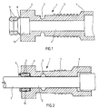
- the cable connector consists of the jacket 1 with an axial channel 2 for an ignition cable 3 (Fig. 2).
- This jacket 1 is subdivided into a plug-in sleeve 4, a shaft part 5 and a head part 6.
- the shaft part 5 and head part 6 are delimited from one another by an annular groove 7 (outside in FIG. 1; alternatively arranged inside in FIG. 2).
- a pair of rolling rings 9 merging into one another adjoins the head part 6 via a film 8.
- a ring shoulder 10 is arranged, which (FIG. 2) is intended for receiving the rolling rings 9.
- the inside diameter of the pair of rolling rings 9 is slightly smaller than the outside diameter of the ignition cable 3, so that when the ignition cable 3 is inserted into the channel 2, the pair of rolling rings 9 is inserted and pushed into the ring shoulder 10. The rolling rings 9 are pressed together and seal the adjoining channel 2 or the gap between the ignition cable 3 and the jacket 1 against moisture.
Landscapes
- Connector Housings Or Holding Contact Members (AREA)
- Spark Plugs (AREA)
- Ignition Installations For Internal Combustion Engines (AREA)
- Communication Cables (AREA)
- Details Of Connecting Devices For Male And Female Coupling (AREA)
Description
- Die Erfindung betrifft einen Kabelstecker für Zündkerzen, bestehend aus einem Mantel aus nichtleitfähigem, flexiblem Kunststoff, insbesondere Silikon, mit einem zentrischen Kanal für die Aufnahme eines Zündkabels.
- Bei derartigen Kabelsteckern besteht die Gefahr, daß zwischen Zündkabel und dem Mantel des Kabelsteckers Feuchtigkeit eindringen kann. Um dies zu vermeiden, besitzt der Kabelsteckermantel meist einen elastischen Ansatz, der das Zündkabel eingangsseitig abdichtend umschließen soll. Es hat sich jedoch gezeigt, daß durch diesen Spalt trotzdem häufig Feuchtigkeit bis an die Zündkerze vordringt.
- Aus der US-A- 1 898 064 ist ein Kabelstecker für Zündkerzen bekannt gemäß dem Oberbegriff des Anspruchs 1.
- Es besteht die Aufgabe, den Kabelstecker der eingangs genannten Art so zu verbessern, daß zwischen Mantel und Zündkabel eingangsseitig eine sichere Abdichtung gegen Feuchtigkeit besteht und daß ein solcher Kabelstecker im Spritzgießverfahren in einfacher weise herstellbar ist.
- Gelöst wird diese Aufgabe mit den im kennzeichnenden Teil des Anspruchs 1 angegebenen Merkmalen.
- Durch diese Ausgestaltung wird erreicht, daß beim Einschieben des Zündkabels in den Kanal des Kabelsteckers bzw. des Mantels der Rollring dank des verbindenden Films bzw. der Stege nach innen eingestülpt und mit in den Ringabsatz hineingezogen wird. Dabei erfährt er infolge der gegebenen Geometrie eine so starke Quetschung, daß der Kanal nach innen zu völlig abgedichtet ist. Beim Spritzen des neuartigen Kabelsteckers bildet sich der Rollring oder deren mehrere, je nach Konstruktion bzw. Formwerkzeug, gleichzeitig mit. Der verbindende Film bzw. die Stege haben an sich keine weitere Funktion, als aus dem Mantel und dem Rollring eine Einheit zu bilden, so daß zusätzliches Hantieren bzw. zusätzliche Lagerhaltung entfallen. Beim Einstülpen des Rollringes ist es ohne Belang, ob der Film bzw. die Stege reißen. Bleibt der Film jedoch unverletzt, so bildet er eine zusätzliche Dichtung zu der Abdichtung zwischen Umfangswand des Ringabsatzes und dem Rollring.
- Vorzugsweise ist der Kabelstecker durch eine konzentrische Ringnut in einen Schaftteil und einen Kopfteil unterteilt, wobei am Kopfteil der Rollring und im Kopfteil der Ringabsatz angeordnet sind.
- Diese Ringnut kann entweder außen oder innen angeordnet sein. Durch die damit bezweckte geringere Dicke im Bereich der Ringnut wird dem Kopfteil eine gewisse Elastizität und Nachgiebigkeit verliehen, um eine Spaltbildung durch Vibration der Einheit auszuschließen.
- In der Zeichnung ist der neuartige Kabelstecker in einem Ausführungsbeispiel rein schematisch im Schnitt dargestellt und nachstehend näher erläutert. Es zeigen:
- Fig. 1
- den Kabelstecker ohne Zündkabel und
- Fig. 2
- den Kabelstecker mit eingeschobenem Zündkabel
- Der Kabelstecker besteht aus dem Mantel 1 mit einem axialen Kanal 2 für ein Zündkabel 3 (Fig. 2). Dieser Mantel 1 ist unterteilt in eine Steckhülse 4, einen Schaftteil 5 sowie einen Kopfteil 6. Schaftteil 5 und Kopfteil 6 sind durch eine Ringnut 7 (in Fig. 1 außen; in Fig. 2 alternativ innen angeordnet) gegeneinander abgegrenzt. Am Kopfteil 6 schließt sich über einen Film 8 ein Paar ineinander übergehender Rollringe 9 an. Im Kopfteil 6 selbst ist ein Ringabsatz 10 angeordnet, welcher (Fig. 2) für die Aufnahme der Rollringe 9 bestimmt ist.
- Der Innendurchmesser des Rollringpaares 9 ist etwas geringer als der Außendurchmesser des Zündkabels 3, so daß beim Einschieben des Zündkabels 3 in den Kanal 2 das Rollringpaar 9 eingestülpt und in den Ringabsatz 10 hineingeschoben wird. Dabei werden die Rollringe 9 zusammengepreßt und dichten den sich anschließenden Kanal 2 bzw. den Spalt zwischen Zündkabel 3 und Mantel 1 gegen Feuchtigkeit ab.
Claims (2)
- Kabelstecker für Zündkerzen, bestehend aus einem Mantel (1) aus nichtleitfähigem, flexiblem Kunststoff, insbesondere Silikon, mit einem zentrischen Kanal (2) für die Aufnahme eines Zündkabels (3), wobei der Mantel (1) an der Eingangsseite für das Zündkabel (3) mindestens einen Rollring (9) aufweist und wobei der Innendurchmesser des Rollringes (9) kleiner ist als die Dicke des Zündkabels (3), dadurch gekennzeichnet, daß der Rollring (9) so an den Mantel (1) angespritzt ist, daß er über einen Film (8) oder Stege mit diesem zumindest ursprünglich verbunden ist, daß der Mantel (1) innenseitig einen koaxialen Ringabsatz (10) zur Aufnahme des Rollringes (9) aufweist und daß die Dicke des Rollringes (9) so bemessen ist, daß er beim Einschieben in den Ringabsatz (10) eine abdichtende Verformung erfährt.
- Kabelstecker nach Anspruch 1, dadurch gekennzeichnet, daß er durch eine konzentrische Ringnut (7) in einen Schaftteil (5) und einen Kopfteil (6) unterteilt ist, wobei am Kopfteil (6) der Rollring (9) und im Kopfteil (6) der Ringabsatz (10) angeordnet sind.
Applications Claiming Priority (2)
| Application Number | Priority Date | Filing Date | Title |
|---|---|---|---|
| DE4101375A DE4101375C1 (de) | 1991-01-18 | 1991-01-18 | |
| DE4101375 | 1991-01-18 |
Publications (2)
| Publication Number | Publication Date |
|---|---|
| EP0495377A1 EP0495377A1 (de) | 1992-07-22 |
| EP0495377B1 true EP0495377B1 (de) | 1995-04-12 |
Family
ID=6423262
Family Applications (1)
| Application Number | Title | Priority Date | Filing Date |
|---|---|---|---|
| EP92100187A Expired - Lifetime EP0495377B1 (de) | 1991-01-18 | 1992-01-08 | Kabelstecker für Zündkerzen |
Country Status (6)
| Country | Link |
|---|---|
| US (1) | US5181856A (de) |
| EP (1) | EP0495377B1 (de) |
| JP (1) | JPH04324275A (de) |
| AT (1) | ATE121228T1 (de) |
| DE (2) | DE4101375C1 (de) |
| ES (1) | ES2072022T3 (de) |
Families Citing this family (9)
| Publication number | Priority date | Publication date | Assignee | Title |
|---|---|---|---|---|
| DE4223818C1 (de) * | 1992-07-20 | 1993-11-25 | Pfisterer Elektrotech Karl | Elastisch verformbarer Isolier- und Dichtungskörper für Kabelstecker u. dgl. |
| JPH07153547A (ja) * | 1993-11-30 | 1995-06-16 | Yazaki Corp | プラグキャップ装置 |
| DE19611283C1 (de) * | 1996-03-22 | 1997-10-23 | Florian Virchow | Zündkerzenstecker für einen Verbrennungsmotor |
| JP3361704B2 (ja) * | 1996-10-25 | 2003-01-07 | 矢崎総業株式会社 | 点火プラグ用プラグキャップ |
| KR20030071212A (ko) * | 2002-02-28 | 2003-09-03 | (주)포스텍 | 일체형 점화케이블 어셈블리 와 그 제조방법 |
| DE102005056328B4 (de) * | 2005-11-25 | 2008-01-31 | Woco Industrietechnik Gmbh | Dichtung, insbesondere Dichtungsmatte, für mindestens einen elektrischen Steckverbinder |
| JP2011181247A (ja) * | 2010-02-26 | 2011-09-15 | Honda Motor Co Ltd | 防水コネクタ及びその組み付け方法 |
| WO2012062855A1 (de) * | 2010-11-12 | 2012-05-18 | Hirschmann Automotive Gmbh | Abdichtung der kontaktkammern gegen spritzmaterial (kunststoff) während dem umspritzprozess |
| DE102018108292B4 (de) | 2017-11-17 | 2023-05-11 | Borgwarner Ludwigsburg Gmbh | Verbindungsstecker zum Anschließen einer Zündspule an eine Zündkerze sowie Schutzrohr für einen Verbindungsstecker |
Family Cites Families (8)
| Publication number | Priority date | Publication date | Assignee | Title |
|---|---|---|---|---|
| US1898064A (en) * | 1927-12-28 | 1933-02-21 | William F Ridge | Insulator for spark plugs |
| US2904769A (en) * | 1953-07-10 | 1959-09-15 | Gen Motors Corp | Spark plug nipple |
| US2707723A (en) * | 1954-06-21 | 1955-05-03 | Walter H Moorhead | Self-locking flexible grommet |
| US2934668A (en) * | 1959-01-16 | 1960-04-26 | Gerald J Dall | Spark plug |
| GB8404107D0 (en) * | 1984-02-16 | 1984-03-21 | Allied Corp | Grommet for connectors |
| WO1988002940A1 (en) * | 1986-10-17 | 1988-04-21 | Gold Securities Australia Limited | Ignition boot |
| US4875875A (en) * | 1987-09-28 | 1989-10-24 | Brintec Corporation | Field terminable modular connector |
| FR2643194B1 (fr) * | 1989-02-14 | 1993-12-17 | Musorb Application Ferrites | Dispositif de connexion electrique d'un cable, notamment d'allumage, sur un plot |
-
1991
- 1991-01-18 DE DE4101375A patent/DE4101375C1/de not_active Expired - Lifetime
- 1991-12-13 US US07/807,301 patent/US5181856A/en not_active Expired - Fee Related
-
1992
- 1992-01-08 EP EP92100187A patent/EP0495377B1/de not_active Expired - Lifetime
- 1992-01-08 AT AT92100187T patent/ATE121228T1/de not_active IP Right Cessation
- 1992-01-08 ES ES92100187T patent/ES2072022T3/es not_active Expired - Lifetime
- 1992-01-08 DE DE59201854T patent/DE59201854D1/de not_active Expired - Fee Related
- 1992-01-14 JP JP4023337A patent/JPH04324275A/ja active Pending
Also Published As
| Publication number | Publication date |
|---|---|
| US5181856A (en) | 1993-01-26 |
| ATE121228T1 (de) | 1995-04-15 |
| EP0495377A1 (de) | 1992-07-22 |
| DE59201854D1 (de) | 1995-05-18 |
| ES2072022T3 (es) | 1995-07-01 |
| JPH04324275A (ja) | 1992-11-13 |
| DE4101375C1 (de) | 1992-04-30 |
Similar Documents
| Publication | Publication Date | Title |
|---|---|---|
| DE69206880T2 (de) | Dichtung für eine elektrische Leitungsschutzrohrkupplung und Kupplung mit dieser Dichtung | |
| DE69903152T2 (de) | Formschlauchkupplungsanordnung | |
| DE2554137A1 (de) | Wellendichtung, und verfahren zu ihrer herstellung | |
| DE10246354B4 (de) | Gleichlaufgelenkmanschette | |
| DE4101375C1 (de) | ||
| DE2927670A1 (de) | Dichtring | |
| EP1308218B1 (de) | Kartuschenkolben mit Entlüftung | |
| WO1986004768A1 (fr) | Boitier forme d'au moins deux parties | |
| DE69208145T2 (de) | Kabelverschraubung | |
| EP0073748B1 (de) | Längsgeteilte druckfeste Kabelmuffe | |
| DE3942701C2 (de) | Verfahren zum Herstellen eines Staubverschlusses | |
| EP3749886B1 (de) | Anschlussteil mit einer dichtung | |
| EP0402653A2 (de) | Kabeleinführungsdichtung | |
| EP0731541B1 (de) | Verschraubung, insb. für Kabel | |
| DE3730427A1 (de) | Anordnung zur befestigung von schlaeuchen an schlauchstutzen | |
| DE4404865C2 (de) | Spritzgieß-Verfahren sowie danach hergestellter Kükenhahn | |
| DE4134260C2 (de) | Hutmutter mit Knickschutz | |
| DE9308181U1 (de) | Anschlußarmatur für Rohre | |
| EP0347608B1 (de) | Dichtring | |
| DE1525461B1 (de) | Wellen- oder Stangendichtung | |
| DE3546435C2 (de) | Quetschverbinder | |
| DE102010018043A1 (de) | Stützring für einen Dichtring | |
| EP0844716B1 (de) | Kabelmuffe | |
| DE3042908A1 (de) | Dichtung zwischen gegeneinander drehbaren bauteilen | |
| EP1422429B1 (de) | Kugelgelenk |
Legal Events
| Date | Code | Title | Description |
|---|---|---|---|
| PUAI | Public reference made under article 153(3) epc to a published international application that has entered the european phase |
Free format text: ORIGINAL CODE: 0009012 |
|
| AK | Designated contracting states |
Kind code of ref document: A1 Designated state(s): AT DE ES FR GB IT SE |
|
| 17P | Request for examination filed |
Effective date: 19920808 |
|
| 17Q | First examination report despatched |
Effective date: 19921222 |
|
| GRAA | (expected) grant |
Free format text: ORIGINAL CODE: 0009210 |
|
| AK | Designated contracting states |
Kind code of ref document: B1 Designated state(s): AT DE ES FR GB IT SE |
|
| REF | Corresponds to: |
Ref document number: 121228 Country of ref document: AT Date of ref document: 19950415 Kind code of ref document: T |
|
| REF | Corresponds to: |
Ref document number: 59201854 Country of ref document: DE Date of ref document: 19950518 |
|
| ITF | It: translation for a ep patent filed | ||
| REG | Reference to a national code |
Ref country code: ES Ref legal event code: FG2A Ref document number: 2072022 Country of ref document: ES Kind code of ref document: T3 |
|
| GBT | Gb: translation of ep patent filed (gb section 77(6)(a)/1977) |
Effective date: 19950605 |
|
| ET | Fr: translation filed | ||
| PLBE | No opposition filed within time limit |
Free format text: ORIGINAL CODE: 0009261 |
|
| STAA | Information on the status of an ep patent application or granted ep patent |
Free format text: STATUS: NO OPPOSITION FILED WITHIN TIME LIMIT |
|
| 26N | No opposition filed | ||
| PGFP | Annual fee paid to national office [announced via postgrant information from national office to epo] |
Ref country code: DE Payment date: 19961212 Year of fee payment: 6 |
|
| PGFP | Annual fee paid to national office [announced via postgrant information from national office to epo] |
Ref country code: SE Payment date: 19961217 Year of fee payment: 6 |
|
| PGFP | Annual fee paid to national office [announced via postgrant information from national office to epo] |
Ref country code: GB Payment date: 19961230 Year of fee payment: 6 |
|
| PGFP | Annual fee paid to national office [announced via postgrant information from national office to epo] |
Ref country code: FR Payment date: 19970122 Year of fee payment: 6 Ref country code: AT Payment date: 19970122 Year of fee payment: 6 |
|
| PGFP | Annual fee paid to national office [announced via postgrant information from national office to epo] |
Ref country code: ES Payment date: 19970127 Year of fee payment: 6 |
|
| PG25 | Lapsed in a contracting state [announced via postgrant information from national office to epo] |
Ref country code: GB Free format text: LAPSE BECAUSE OF NON-PAYMENT OF DUE FEES Effective date: 19980108 Ref country code: AT Free format text: LAPSE BECAUSE OF NON-PAYMENT OF DUE FEES Effective date: 19980108 |
|
| PG25 | Lapsed in a contracting state [announced via postgrant information from national office to epo] |
Ref country code: SE Free format text: LAPSE BECAUSE OF NON-PAYMENT OF DUE FEES Effective date: 19980109 Ref country code: ES Free format text: LAPSE BECAUSE OF EXPIRATION OF PROTECTION Effective date: 19980109 |
|
| PG25 | Lapsed in a contracting state [announced via postgrant information from national office to epo] |
Ref country code: FR Free format text: THE PATENT HAS BEEN ANNULLED BY A DECISION OF A NATIONAL AUTHORITY Effective date: 19980131 |
|
| GBPC | Gb: european patent ceased through non-payment of renewal fee |
Effective date: 19980108 |
|
| PG25 | Lapsed in a contracting state [announced via postgrant information from national office to epo] |
Ref country code: DE Free format text: LAPSE BECAUSE OF NON-PAYMENT OF DUE FEES Effective date: 19981001 |
|
| EUG | Se: european patent has lapsed |
Ref document number: 92100187.1 |
|
| REG | Reference to a national code |
Ref country code: FR Ref legal event code: ST |
|
| REG | Reference to a national code |
Ref country code: ES Ref legal event code: FD2A Effective date: 20000601 |
|
| PG25 | Lapsed in a contracting state [announced via postgrant information from national office to epo] |
Ref country code: IT Free format text: LAPSE BECAUSE OF NON-PAYMENT OF DUE FEES;WARNING: LAPSES OF ITALIAN PATENTS WITH EFFECTIVE DATE BEFORE 2007 MAY HAVE OCCURRED AT ANY TIME BEFORE 2007. THE CORRECT EFFECTIVE DATE MAY BE DIFFERENT FROM THE ONE RECORDED. Effective date: 20050108 |