EP0492352B1 - Sonnensensor für Innenraumtemperaturregeleinrichtungen in Kraftfahrzeugen - Google Patents
Sonnensensor für Innenraumtemperaturregeleinrichtungen in Kraftfahrzeugen Download PDFInfo
- Publication number
- EP0492352B1 EP0492352B1 EP91121561A EP91121561A EP0492352B1 EP 0492352 B1 EP0492352 B1 EP 0492352B1 EP 91121561 A EP91121561 A EP 91121561A EP 91121561 A EP91121561 A EP 91121561A EP 0492352 B1 EP0492352 B1 EP 0492352B1
- Authority
- EP
- European Patent Office
- Prior art keywords
- sun sensor
- housing
- lens
- sensor according
- temperature control
- Prior art date
- Legal status (The legal status is an assumption and is not a legal conclusion. Google has not performed a legal analysis and makes no representation as to the accuracy of the status listed.)
- Expired - Lifetime
Links
Images
Classifications
-
- G—PHYSICS
- G02—OPTICS
- G02B—OPTICAL ELEMENTS, SYSTEMS OR APPARATUS
- G02B7/00—Mountings, adjusting means, or light-tight connections, for optical elements
- G02B7/02—Mountings, adjusting means, or light-tight connections, for optical elements for lenses
-
- B—PERFORMING OPERATIONS; TRANSPORTING
- B60—VEHICLES IN GENERAL
- B60H—ARRANGEMENTS OF HEATING, COOLING, VENTILATING OR OTHER AIR-TREATING DEVICES SPECIALLY ADAPTED FOR PASSENGER OR GOODS SPACES OF VEHICLES
- B60H1/00—Heating, cooling or ventilating [HVAC] devices
- B60H1/00642—Control systems or circuits; Control members or indication devices for heating, cooling or ventilating devices
- B60H1/00735—Control systems or circuits characterised by their input, i.e. by the detection, measurement or calculation of particular conditions, e.g. signal treatment, dynamic models
- B60H1/0075—Control systems or circuits characterised by their input, i.e. by the detection, measurement or calculation of particular conditions, e.g. signal treatment, dynamic models the input being solar radiation
-
- G—PHYSICS
- G01—MEASURING; TESTING
- G01S—RADIO DIRECTION-FINDING; RADIO NAVIGATION; DETERMINING DISTANCE OR VELOCITY BY USE OF RADIO WAVES; LOCATING OR PRESENCE-DETECTING BY USE OF THE REFLECTION OR RERADIATION OF RADIO WAVES; ANALOGOUS ARRANGEMENTS USING OTHER WAVES
- G01S3/00—Direction-finders for determining the direction from which infrasonic, sonic, ultrasonic, or electromagnetic waves, or particle emission, not having a directional significance, are being received
- G01S3/78—Direction-finders for determining the direction from which infrasonic, sonic, ultrasonic, or electromagnetic waves, or particle emission, not having a directional significance, are being received using electromagnetic waves other than radio waves
- G01S3/781—Details
-
- G—PHYSICS
- G02—OPTICS
- G02B—OPTICAL ELEMENTS, SYSTEMS OR APPARATUS
- G02B3/00—Simple or compound lenses
- G02B3/02—Simple or compound lenses with non-spherical faces
Definitions
- the invention relates to a sun sensor for interior temperature control devices in motor vehicles, with an electro-optical converter which has a light-sensitive surface.
- a sun sensor for interior temperature control devices in motor vehicles which has at least one electro-optical converter with at least one light-sensitive surface.
- the sensor has fastening elements for mounting with the motor vehicle.
- the assembly and connection of the sun sensor to an interior temperature control device proves to be particularly difficult.
- the invention is therefore based on the object of providing a sun sensor which has a simple structure and which can be produced and assembled simply and inexpensively.
- the lens is part of a housing and that the housing consists of a translucent material, because in addition to a particularly simple construction of the sun sensor, this results in a particularly simple and inexpensive manufacture of the sun sensor, since the housing and lens are simple and inexpensive a part of plastic or glass, the translucent is, whereby the number of parts to be manufactured and assembled is reduced.
- the housing has first fastening elements and that an electrical circuit board on which the electro-optical converter is mounted and which has an electrical and / or electronic circuit is connected to the housing via the first fastening elements , because this ensures on the one hand that the electro-optical converter is arranged in the correct position and immovable to the lens in its extension and on the other hand an electrical signal is present at the output of the sun sensor, which can be evaluated directly by an interior temperature control device in motor vehicles.
- the housing and / or the cover have second fastening elements, and that a cover is connected to the sun sensor via the second fastening elements, because the sun sensor as a unit is thus simply and inexpensively fixed in position with a cover of the motor vehicle, e.g. B. in the area of the dashboard.
- the part of the housing forming the lens protrudes from the cover by a predetermined amount, because thus depending on the arrangement of the housing, the arrangement and the thickness of the cover and the location of the Installation of the sun sensor ensures that the desired angular range for the sunlight to be detected is not restricted.
- the electro-optical converter is a photodiode and that the circuit is a current-voltage converter, because a voltage signal is thus formed simply and inexpensively from the photocurrent of the photodiode, the z. B. can be processed directly by a microcomputer of an interior temperature control device in motor vehicles.
- the circuit contains an analog / digital converter, because the signal of the sun sensor can be supplied in digital form to a microcomputer of an interior temperature control device for direct processing via a connecting cable.
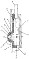
- the only drawing shows a section through a sun sensor according to the invention.
- the sun sensor has a housing (G), which is integrally connected to a lens (L) and is made of translucent plastic or glass.
- the lens (L) protrudes from the housing (G) in a dome shape and has, for example, a lens geometry, the outside of which is determined by the shape of an ellipse and the inside of which is determined by an ellipsoidal cavity.
- a light incidence angle ( ⁇ ) is shown as an example in the drawing.
- the lens (L) of the housing (G) is assigned an electro-optical converter (W) which has a light-sensitive surface (F).
- the assignment and positional arrangement of the electro-optical converter (W) takes place here, in that the electro-optical converter (W) is firmly mounted on a printed circuit board (P), which is correctly and securely attached to the housing via first fastening elements (B1) G) is connected.
- the electro-optical converter (W) projects into an extension of the lens (L) of the housing (G).
- the circuit board (P) in the embodiment shown here has an electrical and / or electronic circuit (S), of which only a part is shown here and which, for. B. may contain a current / voltage converter, which from the current of z. B. a photodiode used, which is used as an electro-optical converter (W), generates a voltage that can be processed by an interior temperature control device in the motor vehicle as a control variable.
- the circuit can also have an analog / digital converter, so that the interior temperature control device, which is not shown here, and is connected to the circuit (S) via a connecting cable (A) which is connected to the circuit board, a digital one Signal is supplied that corresponds to the solar radiation.
- the sun sensor cries off a lid (D) which closes the housing (G) for simple and inexpensive manufacture and assembly.
- the sun sensor thus forms a unit, which consists of the housing (G) of the circuit board (P) and the cover (D) and which is simply over here second fastening elements (B2) shown as examples can be connected to a cover (E) which is part of the motor vehicle.
- the second fastening elements (B2) can be part of the cover and / or the housing (G), depending on how the sun sensor, the cover (E) or the installation location for the sun sensor is designed.
- the shape of the housing, the lens and in particular the lens geometry can differ from the exemplary embodiment shown here, the inside of which is determined by an ellipsoidal cavity.
Landscapes
- Physics & Mathematics (AREA)
- General Physics & Mathematics (AREA)
- Engineering & Computer Science (AREA)
- Optics & Photonics (AREA)
- Thermal Sciences (AREA)
- Mechanical Engineering (AREA)
- Life Sciences & Earth Sciences (AREA)
- Sustainable Development (AREA)
- Electromagnetism (AREA)
- Radar, Positioning & Navigation (AREA)
- Remote Sensing (AREA)
- Photometry And Measurement Of Optical Pulse Characteristics (AREA)
- Studio Devices (AREA)
- Air-Conditioning For Vehicles (AREA)
- Measuring Temperature Or Quantity Of Heat (AREA)
Description
- Die Erfindung betrifft einen Sonnensensor für Innenraumtemperaturregeleinrichtungen in Kraftfahrzeugen, mit einem elektro-optischen Wandler, der eine lichtempfindliche Fläche aufweist.
- Aus der internationalen Patentanmeldung WO-A-90/07102 ist ein Sonnensensor für Innenraumtemperaturregeleinrichtungen in Kraftfahrzeugen bekannt, der mindestens einen elektro-optischen Wandler mit mindestens einer lichtempfindlichen Fläche aufweist. Der Sensor verfügt über Befestigungselemente zur Montage mit dem Kraftfahrzeug.
- Die Montage und der Anschluß des Sonnensensors an eine Innenraumtemperaturregeleinrichtung erweist sich dabei als besonders schwierig.
- Der Erfindung liegt daher die Aufgabe zugrunde, einen Sonnensensor zu schaffen, der einen einfachen Aufbau aufweist und der einfach und kostengünstig herstellbar und montierbar ist.
- Die Aufgabe wird erfindungsgemäß durch die Merkmale des Anspruchs 1 gelöst.
- Es ist von Vorteil, daß die Linse Teil eines Gehäuses ist und daß das Gehäuse aus einem lichtdurchlässigen Material besteht, weil sich somit neben einem besonders einfachen Aufbau des Sonnensensors eine besonders einfache und kostengünstige Herstellbarkeit des Sonnensensors ergibt, da Gehäuse und Linse einfach und kostengünstig aus einem Teil Kunststoff oder Glas bestehen können, das Lichtdurchlässig ist, wodurch die Anzahl der herzustellenden und zu montierenden Teile herabgesetzt wird.
- In diesem Zusammenhang ist es besonders vorteilhaft, daß das Gehäuse erste Befestigungselemente aufweist und daß eine elektrische Leiterplatte, auf der der elektro-optische Wandler montiert ist, und die einen elektrischen und/oder elektronischen Schaltkreis aufweist, über die ersten Befestigungselemente mit dem Gehäuse verbunden ist, weil somit zum einen gewährleistet wird, daß der elektro-optische Wandler lagerichtig und unverrückbar zu der Linse in deren Fortsatz angeordnet ist und zum anderen an dem Ausgang des Sonnensensors ein elektrisches Signal anliegt, das direkt von einer Innenraumtemperaturregeleinrichtung in Kraftfahrzeugen auswertbar ist.
- Dadurch, daß ein Deckel das Gehäuse abschließt, ergibt sich der Vorteil, eines besonders einfachen und kostengünstigen Aufbaus des Sonnensensors, da dieser, bestehend aus dem Gehäuse mit der Linse, der Leiterplatte und dem Deckel eine einfach und kostengünstig herstellbare und zu montierende Einheit bildet.
- Es ist von Vorteil, daß das Gehäuse und/oder der Deckel zweite Befestigungselemente aufweisen, und daß eine Abdeckung über die zweiten Befestigungselemente mit dem Sonnensensor verbunden ist, weil der Sonnensensor somit als Einheit einfach und kostengünstig lagefest mit einer Abdeckung des Kraftfahrzeuges, z. B. im Bereich des Armaturenbrettes, verbindbar ist.
- In diesem Zusammenhang erweist sich als besonders vorteilhaft, daß der die Linse bildende Teil des Gehäuses aus der Abdeckung um einen vorgegebenen Betrag herausragt, weil somit je nach der Anordnung des Gehäuses, der Anordnung und der Dicke der Abdeckung und des Ortes des Einbaus des Sonnensensors sichergestellt ist, daß der gewünschte Winkelbereich für das zu detektierende Sonnenlicht nicht eingeschränkt wird.
- Es ist vorteilhaft, daß der elektro-optische Wandler eine Fotodiode ist und daß der Schaltkreis ein Strom-Spannungswandler ist, weil somit einfach und kostengünstig aus dem Fotostrom der Fotodiode ein Spannungssignal gebildet wird, das z. B. von einem Microrechner einer Innenraumtemperaturregeleinrichtung in Kraftfahrzeugen direkt verarbeitbar ist.
- In diesem Zusammenhang ist es vorteilhaft, wenn der Schaltkreis einen Analog/Digital-Wandler enthält, weil somit einem Microrechner einer Innenraumtemperaturregeleinrichtung das Signal des Sonnensensors in digitaler Form zur direkten Verarbeitung über ein Anschlußkabel zugeführt werden kann.
- Ein Ausführungsbeispiel der Erfindung ist in der einzigen Zeichnung dargestellt und wird im folgenden anhand der Zeichnungen näher erläutert.
- Die einzige Zeichnung zeigt einen Schnitt durch einen erfindungsgemäßen Sonnensensor.
- Der Sonnensensor weist ein Gehäuse (G) auf, das hier einstückig mit einer Linse (L) verbunden ist und aus lichtdurchlässigem Kunststoff oder Glas besteht. Die Linse (L) ragt hier kuppelförmig aus dem Gehäuse (G) hervor und weist beispielhaft eine Linsengeometrie auf, deren Außenseite durch die Form einer Ellipse bestimmt ist und deren Innenseite durch einen ellipsoidförmigen Hohlraum bestimmt ist. In der Zeichnung ist ein Lichteinfallswinkel (α) beispielhaft eingezeichnet.
- Der Linse (L) des Gehäuses (G) ist ein elektro-optischer Wandler (W) zugeordnet, der eine Lichtempfindliche Fläche (F) aufweist. Beispielhaft erfolgt die Zuordnung und lagesichere Anordnung des elektro-optischen Wandlers (W) hier, indem der elektro-optischen Wandler (W) auf einer Leiterplatte (P) fest montiert ist, die über erste Befestigungselemente (B1) lagerichtig und sicher mit dem Gehäuse (G) verbunden ist. Der elektro-optische Wandler (W) ragt dabei in einen Fortsatz der Linse (L) des Gehäuses (G).
- Die Leiterplatte (P) weist bei dem hier gezeigten Ausführungsbeispiel einen elektrischen und/oder elektronischen Schaltkreis (S) auf, von dem hier nur ein Teil gezeigt ist und der z. B. einen Strom/Spannungswandler enthalten kann, der aus dem Strom von z. B. einer verwendeten Fotodiode, die als elektro-optischer Wandler (W) verwendet wird, eine Spannung erzeugt, die von einer Innenraumtemperaturregeleinrichtung in dem Kraftfahrzeug als Regelgröße verarbeitet werden kann. Der Schaltkreis kann zudem auch einen Analog/Digital-Wandler aufweisen, so daß der Innenraumtemperaturregeleinrichtung, die hier nicht gezeigt ist, und über ein Anschlußkabel (A), das mit der Leiterplatte verbunden ist, an den Schaltkreis (S) angeschlossen ist, ein digitales Signal zugeführt wird, das der Sonneneinstrahlung entspricht.
- Für eine einfache und kostengünstige Herstellbarkeit und Montierbarkeit weint der Sonnensensor bei dem hier gezeigten Ausführungsbeispiel einen Deckel (D) auf, der das Gehäuse (G) abschließt. Der Sonnensensor bildet somit eine Einheit, die aus dem Gehäuse (G) der Leiterplatte (P) und dem Deckel (D) besteht und die einfach über hier beispielhaft gezeigte zweite Befestigungselemente (B2) mit einer Abdeckung (E) verbindbar ist, die ein Teil des Kraftfahrzeuges ist. Die zweiten Befestigungselemente (B2) können dabei Teil des Deckels und/oder des Gehäuses (G) sein, je nachdem wie der Sonnensensor, die Abdeckung (E) oder der Einbauort für den Sonnensensor gestaltet ist.
- Je nach dem Einbauort des Sonnensensors, der Dicke und Art der Abdeckung (E), der Anordnung der Lichtempfindlichen Fläche (F) des elektro-optischen Wandlers (W), der möglicherweise vorhandenen Symmetrieachse (Y), der Linse (L) und deren Lage und dem gewünschten zu detektierenden Bereich für den Lichteinfallswinkel (α) ragt die Linse (L) des Gehäuses (G) aus diesem um einen vorbestimmten Betrag heraus, wobei der Betrag dadurch bestimmt ist, daß der Lichteinfall auf die Linse (L) in Abhängigkeit von den vorgenannten Bedingungen nicht eingeschränkt wird.
- Je nach Einbauort des Sonnensensors kann sich die Form des Gehäuses, der Linse und insbesondere der Linsengeometrie von dem hier gezeigten Ausführungsbeispiel unterscheiden, deren Innenseite durch einen ellipsoidförmigen Hohlraum bestimmt ist.
-
- A
- Anschlußkabel
- B1
- erste Befestigungselemente
- B2
- zweite Befestigungselemente
- D
- Deckel
- E
- Abdeckung
- F
- lichtempfindliche Fläche
- G
- Gehäuse
- L
- Linse
- P
- Leiterplatte
- S
- Schaltkreis
- W
- elektro-optischer Wandler
- Y
- Symmetrieachse
- α
- Lichteinfallswinkel
Claims (7)
- Sonnensensor für Innenraumtemperaturregeleinrichtungen in Kraftfahrzeugen, mit einem elektro-optischen Wandler (W), der eine lichtempfindliche Fläche (F) aufweist, dadurch gekennzeichnet, daß der Sonnensensor eine Linse (L) aufweist, daß die Linse (L) Teil eines Gehäuses (G) ist und daß das Gehäuse (G) aus einem lichtdurchlässigen Material besteht.
- Sonnensensor nach Anspruch 1, dadurch gekennzeichnet, daß das Gehäuse (G) erste Befestigungselemente (B1) aufweist und daß eine elektrische Leiterplatte (P), auf der der elektro-optische Wandler montiert ist und die einen elektrischen und/oder elektronischen Schaltkreis (S) aufweist, über die ersten Befestigungselemente (B1) mit dem Gehäuse (G) verbunden ist.
- Sonnensensor nach Anspruch 2, dadurch gekennzeichnet, daß ein Deckel (D) das Gehäuse (G) abschließt.
- Sonnensensor nach Anspruch 3, dadurch gekennzeichnet, daß das Gehäuse (G) und/oder der Deckel (D) zweite Befestigungselemente (B2) aufweisen und daß eine Abdeckung (E) über die zweiten Befestigungselemente (B2) mit dem Sonnensensor verbunden ist.
- Sonnensensor nach Anspruch 4, dadurch gekennzeichnet, daß der die Linse (L) bildende Teil des Gehäuses (G) aus der Abdeckung (E) um einen vorgegebenen Betrag herausragt.
- Sonnensensor nach mindestens einem der vorstehenden Ansprüche, dadurch gekennzeichnet, daß der elektro-optische Wandler (W) eine Fotodiode ist, und daß der Schaltkreis (S) ein Strom/Spannungswandler ist.
- Sonnensensor nach Anspruch 6, dadurch gekennzeichnet, daß der Schaltkreis (S) einen Analog/Digital-Wandler enthält.
Applications Claiming Priority (2)
| Application Number | Priority Date | Filing Date | Title |
|---|---|---|---|
| DE4041770 | 1990-12-24 | ||
| DE4041770A DE4041770C1 (de) | 1990-12-24 | 1990-12-24 |
Publications (3)
| Publication Number | Publication Date |
|---|---|
| EP0492352A2 EP0492352A2 (de) | 1992-07-01 |
| EP0492352A3 EP0492352A3 (en) | 1993-03-31 |
| EP0492352B1 true EP0492352B1 (de) | 1996-07-24 |
Family
ID=6421434
Family Applications (1)
| Application Number | Title | Priority Date | Filing Date |
|---|---|---|---|
| EP91121561A Expired - Lifetime EP0492352B1 (de) | 1990-12-24 | 1991-12-17 | Sonnensensor für Innenraumtemperaturregeleinrichtungen in Kraftfahrzeugen |
Country Status (3)
| Country | Link |
|---|---|
| EP (1) | EP0492352B1 (de) |
| DE (2) | DE4041770C1 (de) |
| ES (1) | ES2089102T3 (de) |
Cited By (1)
| Publication number | Priority date | Publication date | Assignee | Title |
|---|---|---|---|---|
| DE102005043955B4 (de) * | 2005-07-06 | 2007-05-03 | Preh Gmbh | Solarsensor |
Families Citing this family (12)
| Publication number | Priority date | Publication date | Assignee | Title |
|---|---|---|---|---|
| DE4230999A1 (de) * | 1992-09-16 | 1994-03-17 | Bayerische Motoren Werke Ag | Sensor für Kraftfahrzeuge zum Erkennen einer nicht ausreichenden Umgebungshelligkeit |
| FR2702045B1 (fr) * | 1993-02-23 | 1995-05-19 | Fahrzeugklimaregelung Gmbh | Circuit avec un capteur de lumière commandant dans un véhicule automobile un dispositif électronique de commande régulé par la lumière. |
| FR2758627B1 (fr) * | 1997-01-21 | 1999-04-09 | Peugeot | Sonde d'ensoleillement pour une installation de climatisation de vehicule automobile |
| DE19748826C1 (de) * | 1997-11-05 | 1999-02-11 | Kostal Leopold Gmbh & Co Kg | Sonnenstandsdetektor |
| DE19753884A1 (de) * | 1997-12-05 | 1999-06-10 | Behr Gmbh & Co | Sensor zur Erfassung der Sonneneinstrahlung |
| DE19813093C1 (de) * | 1998-03-25 | 1999-04-22 | Opel Adam Ag | Kraftfahrzeug mit einer Heizungs- und Belüftungs- bzw. Klimaanlage |
| DE10062932C2 (de) * | 2000-12-16 | 2003-08-21 | Siemens Ag | Sonnensensor für Kraftfahrzeugklimaanlagen |
| DE10155410C1 (de) | 2001-11-10 | 2003-09-25 | Preh Elektro Feinmechanik | Verfahren zur Steuerung einer Klimaanlage für ein Fahrzeug |
| US7723658B2 (en) | 2003-05-22 | 2010-05-25 | Preh Gmbh | Solar sensor having microspheres on the inside face of the protective cap |
| DE10340346A1 (de) * | 2003-08-29 | 2005-04-28 | Hella Kgaa Hueck & Co | Sensorvorrichtung, insbesondere für Kraftfahrzeuge |
| WO2009027459A2 (de) * | 2007-08-29 | 2009-03-05 | Behr-Hella Thermocontrol Gmbh | Sonnensensor zur erfassung der einfallsrichtung und der intensität von sonnenstrahlung |
| JP5473745B2 (ja) | 2010-04-21 | 2014-04-16 | オムロンオートモーティブエレクトロニクス株式会社 | 光検出装置 |
Family Cites Families (4)
| Publication number | Priority date | Publication date | Assignee | Title |
|---|---|---|---|---|
| JPS54141690A (en) * | 1978-04-26 | 1979-11-05 | Murata Manufacturing Co | Infrared ray detector and making method thereof |
| SE462665B (sv) * | 1988-12-22 | 1990-08-06 | Saab Scania Ab | Givare till en klimatanlaeggning foer fordon |
| JPH1136812A (ja) * | 1997-07-14 | 1999-02-09 | Mitsubishi Heavy Ind Ltd | 軸受台の空気抜き構造 |
| JP3519574B2 (ja) * | 1997-07-24 | 2004-04-19 | 三菱重工業株式会社 | 冷却蒸気配分機構 |
-
1990
- 1990-12-24 DE DE4041770A patent/DE4041770C1/de not_active Expired - Lifetime
-
1991
- 1991-12-17 EP EP91121561A patent/EP0492352B1/de not_active Expired - Lifetime
- 1991-12-17 ES ES91121561T patent/ES2089102T3/es not_active Expired - Lifetime
- 1991-12-17 DE DE59108028T patent/DE59108028D1/de not_active Expired - Lifetime
Cited By (1)
| Publication number | Priority date | Publication date | Assignee | Title |
|---|---|---|---|---|
| DE102005043955B4 (de) * | 2005-07-06 | 2007-05-03 | Preh Gmbh | Solarsensor |
Also Published As
| Publication number | Publication date |
|---|---|
| EP0492352A3 (en) | 1993-03-31 |
| EP0492352A2 (de) | 1992-07-01 |
| DE59108028D1 (de) | 1996-08-29 |
| DE4041770C1 (de) | 1992-07-16 |
| ES2089102T3 (es) | 1996-10-01 |
Similar Documents
| Publication | Publication Date | Title |
|---|---|---|
| EP0492352B1 (de) | Sonnensensor für Innenraumtemperaturregeleinrichtungen in Kraftfahrzeugen | |
| DE10344768B3 (de) | Optisches Modul mit federndem Element zwischen Linsenhalter und Schaltungsträger und optisches System | |
| DE3720406C2 (de) | Lichtsensor | |
| EP0400176B1 (de) | Verfahren zum Montieren eines oberflächenmontierbaren Opto-Bauelements | |
| EP0617260B1 (de) | Fahrzeugniveaugeber | |
| EP0400175B1 (de) | Oberflächenmontierbares Opto-Bauelement | |
| DE102005001712A1 (de) | Fotodetektor | |
| EP0344569B1 (de) | Elektronisches Schaltgerät, insbesondere Näherungsschalter | |
| DE4320939A1 (de) | Dichtung | |
| DE69923472T2 (de) | Solarsensor mit zwei zonen | |
| DE10344767B4 (de) | Optisches Modul und optisches System | |
| DE10022676A1 (de) | Optische Verschiebungsdetektoreinrichtung | |
| EP3111176B1 (de) | Infrarot-bewegungsmelder | |
| DE4300663C1 (de) | Optischer Lenkwinkelsensor | |
| EP0492324A2 (de) | Einrichtung zur Regelung der Innenraumtemperatur von Kraftfahrzeugen | |
| EP0893003B1 (de) | Elektromotor | |
| DE10335906A1 (de) | Kameraanordnung | |
| EP2530351B1 (de) | Optikträger | |
| EP0732230B1 (de) | Klimaanlage für Kraftfahrzeuge | |
| EP2560038B1 (de) | Optikträger und Montageverfahren | |
| DE19543372C5 (de) | Winkelmeßeinrichtung | |
| DE102005008885B4 (de) | Lichtgitter | |
| DE4142108C2 (de) | Montagestruktur für ein optisches Bauteil einer Optikeinrichtung | |
| EP0922627A1 (de) | Modulare Anordnung eines Lenkwinkelsensors | |
| EP1282092A2 (de) | Raumsensor mit Montageadapter |
Legal Events
| Date | Code | Title | Description |
|---|---|---|---|
| PUAI | Public reference made under article 153(3) epc to a published international application that has entered the european phase |
Free format text: ORIGINAL CODE: 0009012 |
|
| AK | Designated contracting states |
Kind code of ref document: A2 Designated state(s): DE ES FR GB IT |
|
| PUAL | Search report despatched |
Free format text: ORIGINAL CODE: 0009013 |
|
| AK | Designated contracting states |
Kind code of ref document: A3 Designated state(s): DE ES FR GB IT |
|
| 17P | Request for examination filed |
Effective date: 19930819 |
|
| 17Q | First examination report despatched |
Effective date: 19950222 |
|
| GRAG | Despatch of communication of intention to grant |
Free format text: ORIGINAL CODE: EPIDOS AGRA |
|
| GRAH | Despatch of communication of intention to grant a patent |
Free format text: ORIGINAL CODE: EPIDOS IGRA |
|
| GRAH | Despatch of communication of intention to grant a patent |
Free format text: ORIGINAL CODE: EPIDOS IGRA |
|
| GRAA | (expected) grant |
Free format text: ORIGINAL CODE: 0009210 |
|
| ITF | It: translation for a ep patent filed |
Owner name: INTERPATENT ST.TECN. BREV. |
|
| AK | Designated contracting states |
Kind code of ref document: B1 Designated state(s): DE ES FR GB IT |
|
| REF | Corresponds to: |
Ref document number: 59108028 Country of ref document: DE Date of ref document: 19960829 |
|
| GBT | Gb: translation of ep patent filed (gb section 77(6)(a)/1977) |
Effective date: 19960823 |
|
| REG | Reference to a national code |
Ref country code: ES Ref legal event code: FG2A Ref document number: 2089102 Country of ref document: ES Kind code of ref document: T3 |
|
| ET | Fr: translation filed | ||
| REG | Reference to a national code |
Ref country code: ES Ref legal event code: FG2A Ref document number: 2089102 Country of ref document: ES Kind code of ref document: T3 |
|
| PLBE | No opposition filed within time limit |
Free format text: ORIGINAL CODE: 0009261 |
|
| STAA | Information on the status of an ep patent application or granted ep patent |
Free format text: STATUS: NO OPPOSITION FILED WITHIN TIME LIMIT |
|
| 26N | No opposition filed | ||
| PGFP | Annual fee paid to national office [announced via postgrant information from national office to epo] |
Ref country code: GB Payment date: 19981120 Year of fee payment: 8 |
|
| PGFP | Annual fee paid to national office [announced via postgrant information from national office to epo] |
Ref country code: ES Payment date: 19981211 Year of fee payment: 8 |
|
| PGFP | Annual fee paid to national office [announced via postgrant information from national office to epo] |
Ref country code: FR Payment date: 19981216 Year of fee payment: 8 |
|
| PG25 | Lapsed in a contracting state [announced via postgrant information from national office to epo] |
Ref country code: GB Free format text: LAPSE BECAUSE OF NON-PAYMENT OF DUE FEES Effective date: 19991217 |
|
| GBPC | Gb: european patent ceased through non-payment of renewal fee |
Effective date: 19991217 |
|
| PG25 | Lapsed in a contracting state [announced via postgrant information from national office to epo] |
Ref country code: FR Free format text: LAPSE BECAUSE OF NON-PAYMENT OF DUE FEES Effective date: 20000831 |
|
| REG | Reference to a national code |
Ref country code: FR Ref legal event code: ST |
|
| PG25 | Lapsed in a contracting state [announced via postgrant information from national office to epo] |
Ref country code: ES Free format text: LAPSE BECAUSE OF NON-PAYMENT OF DUE FEES Effective date: 20001218 |
|
| REG | Reference to a national code |
Ref country code: ES Ref legal event code: FD2A Effective date: 20010113 |
|
| PG25 | Lapsed in a contracting state [announced via postgrant information from national office to epo] |
Ref country code: IT Free format text: LAPSE BECAUSE OF NON-PAYMENT OF DUE FEES;WARNING: LAPSES OF ITALIAN PATENTS WITH EFFECTIVE DATE BEFORE 2007 MAY HAVE OCCURRED AT ANY TIME BEFORE 2007. THE CORRECT EFFECTIVE DATE MAY BE DIFFERENT FROM THE ONE RECORDED. Effective date: 20051217 |
|
| PGFP | Annual fee paid to national office [announced via postgrant information from national office to epo] |
Ref country code: DE Payment date: 20101229 Year of fee payment: 20 |
|
| REG | Reference to a national code |
Ref country code: DE Ref legal event code: R071 Ref document number: 59108028 Country of ref document: DE |
|
| REG | Reference to a national code |
Ref country code: DE Ref legal event code: R071 Ref document number: 59108028 Country of ref document: DE |
|
| PG25 | Lapsed in a contracting state [announced via postgrant information from national office to epo] |
Ref country code: DE Free format text: LAPSE BECAUSE OF EXPIRATION OF PROTECTION Effective date: 20111218 |