EP0491445B1 - Verfahren zur adaptiven Regelung positionierbarer Antriebe - Google Patents
Verfahren zur adaptiven Regelung positionierbarer Antriebe Download PDFInfo
- Publication number
- EP0491445B1 EP0491445B1 EP91250299A EP91250299A EP0491445B1 EP 0491445 B1 EP0491445 B1 EP 0491445B1 EP 91250299 A EP91250299 A EP 91250299A EP 91250299 A EP91250299 A EP 91250299A EP 0491445 B1 EP0491445 B1 EP 0491445B1
- Authority
- EP
- European Patent Office
- Prior art keywords
- zone
- control
- drive
- positions
- parameters
- Prior art date
- Legal status (The legal status is an assumption and is not a legal conclusion. Google has not performed a legal analysis and makes no representation as to the accuracy of the status listed.)
- Expired - Lifetime
Links
- 238000000034 method Methods 0.000 title claims description 20
- 230000003044 adaptive effect Effects 0.000 title claims description 15
- 230000001133 acceleration Effects 0.000 claims description 6
- 230000001419 dependent effect Effects 0.000 description 9
- 230000006978 adaptation Effects 0.000 description 5
- 238000010586 diagram Methods 0.000 description 2
- 238000010079 rubber tapping Methods 0.000 description 2
- 125000002015 acyclic group Chemical group 0.000 description 1
- 230000006399 behavior Effects 0.000 description 1
- 238000013016 damping Methods 0.000 description 1
- 238000005516 engineering process Methods 0.000 description 1
- 238000011156 evaluation Methods 0.000 description 1
- 239000012530 fluid Substances 0.000 description 1
- 238000009434 installation Methods 0.000 description 1
- 230000010354 integration Effects 0.000 description 1
- 238000005457 optimization Methods 0.000 description 1
- 230000004044 response Effects 0.000 description 1
- 238000013316 zoning Methods 0.000 description 1
Images


Classifications
-
- G—PHYSICS
- G05—CONTROLLING; REGULATING
- G05B—CONTROL OR REGULATING SYSTEMS IN GENERAL; FUNCTIONAL ELEMENTS OF SUCH SYSTEMS; MONITORING OR TESTING ARRANGEMENTS FOR SUCH SYSTEMS OR ELEMENTS
- G05B19/00—Programme-control systems
- G05B19/02—Programme-control systems electric
- G05B19/18—Numerical control [NC], i.e. automatically operating machines, in particular machine tools, e.g. in a manufacturing environment, so as to execute positioning, movement or co-ordinated operations by means of programme data in numerical form
- G05B19/19—Numerical control [NC], i.e. automatically operating machines, in particular machine tools, e.g. in a manufacturing environment, so as to execute positioning, movement or co-ordinated operations by means of programme data in numerical form characterised by positioning or contouring control systems, e.g. to control position from one programmed point to another or to control movement along a programmed continuous path
-
- G—PHYSICS
- G05—CONTROLLING; REGULATING
- G05B—CONTROL OR REGULATING SYSTEMS IN GENERAL; FUNCTIONAL ELEMENTS OF SUCH SYSTEMS; MONITORING OR TESTING ARRANGEMENTS FOR SUCH SYSTEMS OR ELEMENTS
- G05B19/00—Programme-control systems
- G05B19/02—Programme-control systems electric
- G05B19/18—Numerical control [NC], i.e. automatically operating machines, in particular machine tools, e.g. in a manufacturing environment, so as to execute positioning, movement or co-ordinated operations by means of programme data in numerical form
- G05B19/414—Structure of the control system, e.g. common controller or multiprocessor systems, interface to servo, programmable interface controller
- G05B19/4142—Structure of the control system, e.g. common controller or multiprocessor systems, interface to servo, programmable interface controller characterised by the use of a microprocessor
-
- G—PHYSICS
- G05—CONTROLLING; REGULATING
- G05B—CONTROL OR REGULATING SYSTEMS IN GENERAL; FUNCTIONAL ELEMENTS OF SUCH SYSTEMS; MONITORING OR TESTING ARRANGEMENTS FOR SUCH SYSTEMS OR ELEMENTS
- G05B2219/00—Program-control systems
- G05B2219/30—Nc systems
- G05B2219/33—Director till display
- G05B2219/33119—Servo parameters in memory, configuration of control parameters
-
- G—PHYSICS
- G05—CONTROLLING; REGULATING
- G05B—CONTROL OR REGULATING SYSTEMS IN GENERAL; FUNCTIONAL ELEMENTS OF SUCH SYSTEMS; MONITORING OR TESTING ARRANGEMENTS FOR SUCH SYSTEMS OR ELEMENTS
- G05B2219/00—Program-control systems
- G05B2219/30—Nc systems
- G05B2219/34—Director, elements to supervisory
- G05B2219/34448—Integrated servo control circuit fixed to housing, remote from cpu
-
- G—PHYSICS
- G05—CONTROLLING; REGULATING
- G05B—CONTROL OR REGULATING SYSTEMS IN GENERAL; FUNCTIONAL ELEMENTS OF SUCH SYSTEMS; MONITORING OR TESTING ARRANGEMENTS FOR SUCH SYSTEMS OR ELEMENTS
- G05B2219/00—Program-control systems
- G05B2219/30—Nc systems
- G05B2219/37—Measurements
- G05B2219/37621—Inertia, mass of rotating, moving tool, workpiece, element
-
- G—PHYSICS
- G05—CONTROLLING; REGULATING
- G05B—CONTROL OR REGULATING SYSTEMS IN GENERAL; FUNCTIONAL ELEMENTS OF SUCH SYSTEMS; MONITORING OR TESTING ARRANGEMENTS FOR SUCH SYSTEMS OR ELEMENTS
- G05B2219/00—Program-control systems
- G05B2219/30—Nc systems
- G05B2219/41—Servomotor, servo controller till figures
- G05B2219/41143—Compensation of dynamic characteristic of actuator
-
- G—PHYSICS
- G05—CONTROLLING; REGULATING
- G05B—CONTROL OR REGULATING SYSTEMS IN GENERAL; FUNCTIONAL ELEMENTS OF SUCH SYSTEMS; MONITORING OR TESTING ARRANGEMENTS FOR SUCH SYSTEMS OR ELEMENTS
- G05B2219/00—Program-control systems
- G05B2219/30—Nc systems
- G05B2219/41—Servomotor, servo controller till figures
- G05B2219/41176—Compensation control, position error with data from lookup memory
-
- G—PHYSICS
- G05—CONTROLLING; REGULATING
- G05B—CONTROL OR REGULATING SYSTEMS IN GENERAL; FUNCTIONAL ELEMENTS OF SUCH SYSTEMS; MONITORING OR TESTING ARRANGEMENTS FOR SUCH SYSTEMS OR ELEMENTS
- G05B2219/00—Program-control systems
- G05B2219/30—Nc systems
- G05B2219/41—Servomotor, servo controller till figures
- G05B2219/41301—Pilot valve, linear fluid control valve and power cylinder
Definitions
- the invention relates to a method for adaptive control of positionable drives, according to the preamble of patent claim 1.
- control parameters to be assigned to the corresponding travel movement are directed in a self-learning process Shorter travel times optimized and saved.
- the control parameters are predetermined during the first run and are determined as optimized control parameters by practical optimization at the target point during the repeated run and saved for the next run.
- Such systems are generally referred to as adaptive controls.
- adaptive controls Such a control concept is known from the article by Professor Rusterholz (7th Aachen Fluid Technology Colloquium March 1986).
- the control parameters are adapted to the current system parameters and are referred to as controlled adaptation.
- the corresponding control parameters are then read from a read-only memory of a microcomputer and fed into the control process.
- the position of the start and target position has a decisive influence on the optimal size of the adaptive control parameters, since depending on the position of the movable drive part, the compressed air volumes in the cylinder tube to be controlled by the valves can vary greatly.
- This position dependency is also taken into account in this known method by providing a set of adaptive control parameters from a corresponding read-only memory for each position of the drive part of the servopneumatic drive and, if necessary, correcting them on the basis of observed deviations from the control target and making them available for the next similar task.
- various sizes are used as a key figure in known control methods. The assignment of the parameter set to the stored target position, the route or the step number of the machine cycle is known.
- the object of the invention is therefore to provide a method of the generic type that overshoot in the target position can be avoided even with a non-cyclical positioning sequence by reducing the cycle times.
- the proposal according to the invention that in the case of a method for adaptive control of positionable drives, according to the invention a travel distance between their attachment points which is decisive for an operational sequence determined and divided into calculated numbered distance or angle zones and stored in a data memory, has the advantage that at each start of operation of the positionable drive an optimal adaptation of the dimensional conditions of an individually planned operation to the physical control parameters, such as driving speed, driving acceleration, Compressed air quantities, etc., can be made. With the help of the distances or angular zones determined in this way, the variables describing the travel movements are determined and in each case divided into a numbered zone system and stored in the data memory. This has the advantage that access between line or angular zones and the optimal control parameters or the control signals ultimately output is ensured in a simple form.
- Calculating the data address for the control parameters of the control parameter field from the number of a zone of a first zone system and the number of a zone of at least one further zone system allows an optimal adaptation to the physically given conditions.
- the improvement of this method is based on the fact that not only a single criterion, such as e.g. B. target position or block number of the machine cycle is used, but two or more independent key figures are derived from the positioning task, which are linked together to form an index and thus give access to the field of the control parameter memory.
- the possible start positions are used as the first zone system and the possible target positions of the drive are used as the second zone system in order to reach the data addresses in the control parameter field.
- a further advantageous embodiment results when the possible start or target positions are used as the first zone system and the possible travel routes or travel angles of the drive are used as the second zone system to calculate the data address of the control parameter field.
- the travel speeds specified in the positioning tasks form a further zone system, the number of which is also used to calculate the data address in the control parameter field.
- Another possibility is to take the mass load into account as a further zone system, the number of the corresponding mass load zone being determined from the start acceleration and the corresponding number of the zone being used to determine the data address in the control parameter field.
- the consideration of the payload arises from the consideration of the mass load and has the advantage of a regulation adapted to every possible operating situation.
- Access to the start and target positions and other given physical parameters in combination with the measure of then dividing them into corresponding zones and finding the data address of the optimal controller parameters from the indices of these zones allows a minimal travel even with acyclic positioning tasks. or to achieve cycle time and at the same time to prevent the positionable drive from overshooting in the target position.
- Linear drive A consisting of cylinder tube A1, cylinder heads A2, A3 and slide A4.
- a scale system M1 for tapping the slide position is arranged on the cylinder tube A1.
- the measuring head M2 connected to the slide A4 engages in this measuring rod system and reproducibly reproduces the position of the slide. All parameters relevant to the movement can be determined and derived from this position tap.
- the determined position values can also be used to determine acceleration, driving speed, start and target position and mass load.
- the mass load is derived from the determined starting acceleration and takes into account both the payload to be moved as well as the mass of the piston and the associated means such as tension band etc., and possibly also the friction.
- the cylinder heads A2, A3 are each connected to a servo valve V1, V2, the servo valves being expediently arranged integrated in the cylinder heads, which means that on the one hand there are no losses via additional lines and on the other hand the servo valve with a correspondingly short response time acted on the cylinder spaces in the cylinder barrel.
- the servo valves V1, V2 and the tapping of the measuring system on the slide are controlled or tapped via a digital controller D.
- the electrical control connection of the valve V1 is connected to the control signal output interface D3 of the digital controller D.
- the control connection of the servo valve V2 is also connected to this control signal output interface D3.
- the tap of the measuring system on the slide is electrically connected to the actual value input interface D2.
- the actual value input interface D2 has a connection to the control signal output interface D3 and a connection to the setpoint input and command interface D1.
- a data line leads from the setpoint input and command interface D1 and the control signal output interface D3 to a microprocessor D4, which on the output side is connected both to the setpoint memory D5 and to the memory for adaptive control parameters D7.
- the control program memory D6 in turn establishes the connection between the setpoint memory D5 and the memory for the adaptive control parameters D7.
- the setpoint input and command interface D1 has a direct connection to the computer or the control system by calculating the determination of the physical quantities and the calculation of the data addresses as well as the adaptation of the control parameters to the physical conditions.
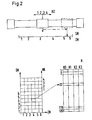
- FIG. 2 shows the diagram after, for example, the start and target position and the stroke of the slide form the corresponding zone systems.
- the Zones are determined by running a test run initiated at the beginning of the operational sequence, the route relevant to the operational sequence between the anchor points, determining the anchor points, storing them, dividing the route into zones and storing them in a computer.
- the example shown in FIG. 2 then follows the division into start, target and stroke zones. It is not important that these zones are distributed equidistantly, but rather the possibility is to be used with the aid of the computer, for example to carry out a logarithmic division of the zones. This has an advantage in particular if the entire stroke length is very large and the pressure volumes to be pressurized with compressed air therefore vary very greatly. This adjustment is necessary once after installation, ie adjustment of the drive to the work task.
- FIG. 3 shows the diagram from FIG. 2 according to which the data addresses are determined in detail.
- the stroke positions or stroke lengths are divided into four zones. That is why Scheme already shown in Figure 2 and detailed in Figure 3.
- Each square, ie each square within the field, is assigned two numbers, which in combination make it possible to correlate the three zone systems with one another. This sense of the two numbers per square is illustrated by an example. If the starting point is in the starting zone 4 and the target point in the target zone 4, the square with the number combination 22/58 results in the field.
- parameter set 22 is activated with a short stroke and parameter set 58 with a large stroke.
- the given configuration option is a total of 120 parameter sets. It is these parameter sets that then result in the digits of the combination of two numbers per square in the field.
- Another example is a so-called stroke-dependent control. If the desired target position is in target zone 5 and the stroke is in the range of stroke zone 1, the square in the zone field with the numbers 77/110 results; which then determine the data address in the control parameter field in a corresponding manner.
Landscapes
- Engineering & Computer Science (AREA)
- Human Computer Interaction (AREA)
- Manufacturing & Machinery (AREA)
- Physics & Mathematics (AREA)
- General Physics & Mathematics (AREA)
- Automation & Control Theory (AREA)
- Computer Hardware Design (AREA)
- Microelectronics & Electronic Packaging (AREA)
- Feedback Control In General (AREA)
- Control Of Position Or Direction (AREA)
Applications Claiming Priority (2)
| Application Number | Priority Date | Filing Date | Title |
|---|---|---|---|
| DE4040796 | 1990-12-17 | ||
| DE4040796A DE4040796A1 (de) | 1990-12-17 | 1990-12-17 | Verfahren zur adaptiven regelung positionierbarer antriebe |
Publications (3)
| Publication Number | Publication Date |
|---|---|
| EP0491445A2 EP0491445A2 (de) | 1992-06-24 |
| EP0491445A3 EP0491445A3 (en) | 1993-03-31 |
| EP0491445B1 true EP0491445B1 (de) | 1996-07-10 |
Family
ID=6420792
Family Applications (1)
| Application Number | Title | Priority Date | Filing Date |
|---|---|---|---|
| EP91250299A Expired - Lifetime EP0491445B1 (de) | 1990-12-17 | 1991-10-31 | Verfahren zur adaptiven Regelung positionierbarer Antriebe |
Country Status (4)
| Country | Link |
|---|---|
| US (1) | US5347445A (enExample) |
| EP (1) | EP0491445B1 (enExample) |
| JP (1) | JPH04294409A (enExample) |
| DE (2) | DE4040796A1 (enExample) |
Families Citing this family (7)
| Publication number | Priority date | Publication date | Assignee | Title |
|---|---|---|---|---|
| JP3053144B2 (ja) * | 1992-08-17 | 2000-06-19 | セイコーエプソン株式会社 | プリンタのキャリッジモータ制御装置 |
| DE4319715C2 (de) * | 1993-06-15 | 1995-08-17 | Kodak Ag | Verfahren zum Bewegen eines Drehkörpers |
| JPH08286758A (ja) * | 1995-04-11 | 1996-11-01 | Canon Inc | 位置決め装置 |
| DE19518431A1 (de) * | 1995-05-19 | 1996-11-21 | Danfoss As | Verfahren zum Fernbedienen einer elektrohydraulischen Steuervorrichtung und Fernbedienungseinrichtung |
| DE19632914A1 (de) * | 1996-08-16 | 1998-02-19 | Festo Ag & Co | Verfahren zur Positionierung von servopneumatischen Antrieben mittels adaptiver Regelung |
| SE0100974D0 (sv) * | 2001-03-20 | 2001-03-20 | Abb Ab | Termisk optimeringsmetod |
| RU2629378C1 (ru) * | 2016-04-12 | 2017-08-29 | Общество с ограниченной ответственностью Научно-производственное предприятие "ЭКРА" | Способ построения адаптивной системы автоматического управления возбуждением |
Family Cites Families (11)
| Publication number | Priority date | Publication date | Assignee | Title |
|---|---|---|---|---|
| US3996590A (en) * | 1961-02-02 | 1976-12-07 | Hammack Calvin M | Method and apparatus for automatically detecting and tracking moving objects and similar applications |
| GB2082348A (en) * | 1980-08-19 | 1982-03-03 | Garland John Joseph | A Control System for use in Conjunction with a Machine Tool |
| DE3121048A1 (de) * | 1981-05-27 | 1982-12-16 | Licentia Patent-Verwaltungs-Gmbh, 6000 Frankfurt | Anordnung zur steuerung der geschwindigkeit eines von einem antrieb bewegbaren gegenstands |
| US4536842A (en) * | 1982-03-31 | 1985-08-20 | Tokyo Shibaura Denki Kabushiki Kaisha | System for measuring interfloor traffic for group control of elevator cars |
| US4488236A (en) * | 1982-04-16 | 1984-12-11 | United Technologies Corporation | Helicopter cruise fuel conserving engine control |
| DE3445048A1 (de) * | 1984-12-11 | 1986-06-19 | Reis GmbH & Co, 8753 Obernburg | Verfahren zum programmieren eines trainingsarms fuer einen manipulator |
| US4761595A (en) * | 1987-05-01 | 1988-08-02 | General Motors Corporation | Motion control system having adaptive feedforward path tracking |
| US5091858A (en) * | 1989-01-09 | 1992-02-25 | Digital Fuel Injection | Electronic control of engine fuel delivery |
| US5121443A (en) * | 1989-04-25 | 1992-06-09 | Spectra-Physics, Inc. | Neural net system for analyzing chromatographic peaks |
| US4922468A (en) * | 1989-06-02 | 1990-05-01 | Sonalysts, Inc. | Method and apparatus for controlling aquatic population in defined areas |
| US5014051A (en) * | 1989-12-26 | 1991-05-07 | Delco Electronics Corporation | Increased resolution sensor circuit |
-
1990
- 1990-12-17 DE DE4040796A patent/DE4040796A1/de active Granted
-
1991
- 1991-10-31 EP EP91250299A patent/EP0491445B1/de not_active Expired - Lifetime
- 1991-10-31 DE DE59107992T patent/DE59107992D1/de not_active Expired - Fee Related
- 1991-12-17 JP JP3353506A patent/JPH04294409A/ja active Pending
- 1991-12-17 US US07/808,668 patent/US5347445A/en not_active Expired - Fee Related
Also Published As
| Publication number | Publication date |
|---|---|
| US5347445A (en) | 1994-09-13 |
| DE59107992D1 (de) | 1996-08-14 |
| JPH04294409A (ja) | 1992-10-19 |
| EP0491445A2 (de) | 1992-06-24 |
| EP0491445A3 (en) | 1993-03-31 |
| DE4040796C2 (enExample) | 1992-09-24 |
| DE4040796A1 (de) | 1992-07-02 |
Similar Documents
| Publication | Publication Date | Title |
|---|---|---|
| DE3600364C2 (enExample) | ||
| DE4215716C2 (de) | Steuervorrichtung für den Legeschienenversatz bei Kettenwirkmaschinen | |
| DE2735632A1 (de) | Verfahren und anordnung zum steuern eines industrie-roboters | |
| DE3732813C2 (enExample) | ||
| DE1638032B2 (de) | Numerisch arbeitende Programmsteuerung | |
| DE3134091A1 (de) | Mikroprozessorgestuetzte prozesssteuerung | |
| DE3408523C2 (enExample) | ||
| DE3404205A1 (de) | Steuereinrichtung fuer ein fluessigkeitsventil | |
| DE3886748T2 (de) | Geschwindigkeitsregelanordnung. | |
| EP0419706B1 (de) | Verfahren zur numerischen Positions- oder Bahnsteuerung | |
| EP0491445B1 (de) | Verfahren zur adaptiven Regelung positionierbarer Antriebe | |
| DE3889496T2 (de) | Elektrohydraulische Servo-Antriebe. | |
| DE1538656A1 (de) | Hybride Verhaeltnisregelung | |
| EP0561813B1 (de) | Verfahren zur ermittlung von vorsteuerparametern für eine lageregelung | |
| DE102018216561A1 (de) | Verfahren, Vorrichtung und Computerprogramm zum Ermitteln einer Strategie eines Agenten | |
| DE68910500T2 (de) | Ortungsverfahren für eine elektrisch angetriebene einspritzformgiessvorrichtung. | |
| DE3700887C2 (enExample) | ||
| DE1923917C3 (de) | Werkzeugmaschinenantriebssteuerung mittels eines Rechners | |
| DE69100887T2 (de) | Verfahren und Gerät zum Steuern einer oder mehrerer Achsen einer Werkzeugmaschine. | |
| EP0791193B1 (de) | Satzübergreifende geschwindigkeitsführung für beliebigen override-bereich | |
| EP0672976B1 (de) | Elektronische Steuereinrichtung für Einzelantriebe von Bearbeitungsmaschinen und Verfahren zum Steuern der Einzelantriebe | |
| DE2165862C2 (de) | Adaptive Steuerungsvorrichtung für numerisch gesteuerte Werkzeugmaschinen | |
| DE4026413C2 (de) | Positionier-Steuervorrichtung | |
| DD258382B1 (de) | Verfahren zur antriebssteuerung einer presse und einer transfereinrichtung | |
| DE102016009443A1 (de) | Numerische Steuerung zum Durchführen von Achsensteuerung von zwei parallelen Achsen |
Legal Events
| Date | Code | Title | Description |
|---|---|---|---|
| PUAI | Public reference made under article 153(3) epc to a published international application that has entered the european phase |
Free format text: ORIGINAL CODE: 0009012 |
|
| AK | Designated contracting states |
Kind code of ref document: A2 Designated state(s): BE CH DE FR GB LI NL SE |
|
| PUAL | Search report despatched |
Free format text: ORIGINAL CODE: 0009013 |
|
| AK | Designated contracting states |
Kind code of ref document: A3 Designated state(s): BE CH DE FR GB LI NL SE |
|
| 17P | Request for examination filed |
Effective date: 19930302 |
|
| 17Q | First examination report despatched |
Effective date: 19941209 |
|
| GRAH | Despatch of communication of intention to grant a patent |
Free format text: ORIGINAL CODE: EPIDOS IGRA |
|
| GRAH | Despatch of communication of intention to grant a patent |
Free format text: ORIGINAL CODE: EPIDOS IGRA |
|
| GRAA | (expected) grant |
Free format text: ORIGINAL CODE: 0009210 |
|
| AK | Designated contracting states |
Kind code of ref document: B1 Designated state(s): BE CH DE FR GB LI NL SE |
|
| PG25 | Lapsed in a contracting state [announced via postgrant information from national office to epo] |
Ref country code: NL Free format text: LAPSE BECAUSE OF FAILURE TO SUBMIT A TRANSLATION OF THE DESCRIPTION OR TO PAY THE FEE WITHIN THE PRESCRIBED TIME-LIMIT Effective date: 19960710 |
|
| REG | Reference to a national code |
Ref country code: CH Ref legal event code: NV Representative=s name: E. BLUM & CO. PATENTANWAELTE |
|
| REF | Corresponds to: |
Ref document number: 59107992 Country of ref document: DE Date of ref document: 19960814 |
|
| ET | Fr: translation filed | ||
| GBT | Gb: translation of ep patent filed (gb section 77(6)(a)/1977) |
Effective date: 19960820 |
|
| PGFP | Annual fee paid to national office [announced via postgrant information from national office to epo] |
Ref country code: GB Payment date: 19960916 Year of fee payment: 6 |
|
| PGFP | Annual fee paid to national office [announced via postgrant information from national office to epo] |
Ref country code: FR Payment date: 19960920 Year of fee payment: 6 Ref country code: CH Payment date: 19960920 Year of fee payment: 6 |
|
| PGFP | Annual fee paid to national office [announced via postgrant information from national office to epo] |
Ref country code: BE Payment date: 19960924 Year of fee payment: 6 |
|
| PG25 | Lapsed in a contracting state [announced via postgrant information from national office to epo] |
Ref country code: SE Effective date: 19961010 |
|
| NLV1 | Nl: lapsed or annulled due to failure to fulfill the requirements of art. 29p and 29m of the patents act | ||
| PLBE | No opposition filed within time limit |
Free format text: ORIGINAL CODE: 0009261 |
|
| STAA | Information on the status of an ep patent application or granted ep patent |
Free format text: STATUS: NO OPPOSITION FILED WITHIN TIME LIMIT |
|
| 26N | No opposition filed | ||
| PG25 | Lapsed in a contracting state [announced via postgrant information from national office to epo] |
Ref country code: LI Free format text: LAPSE BECAUSE OF NON-PAYMENT OF DUE FEES Effective date: 19971031 Ref country code: GB Free format text: LAPSE BECAUSE OF NON-PAYMENT OF DUE FEES Effective date: 19971031 Ref country code: FR Free format text: THE PATENT HAS BEEN ANNULLED BY A DECISION OF A NATIONAL AUTHORITY Effective date: 19971031 Ref country code: CH Free format text: LAPSE BECAUSE OF NON-PAYMENT OF DUE FEES Effective date: 19971031 Ref country code: BE Free format text: LAPSE BECAUSE OF NON-PAYMENT OF DUE FEES Effective date: 19971031 |
|
| BERE | Be: lapsed |
Owner name: MANNESMANN A.G. Effective date: 19971031 |
|
| REG | Reference to a national code |
Ref country code: CH Ref legal event code: PL |
|
| GBPC | Gb: european patent ceased through non-payment of renewal fee |
Effective date: 19971031 |
|
| REG | Reference to a national code |
Ref country code: FR Ref legal event code: ST |
|
| PGFP | Annual fee paid to national office [announced via postgrant information from national office to epo] |
Ref country code: DE Payment date: 20011221 Year of fee payment: 11 |
|
| PG25 | Lapsed in a contracting state [announced via postgrant information from national office to epo] |
Ref country code: DE Free format text: LAPSE BECAUSE OF NON-PAYMENT OF DUE FEES Effective date: 20030501 |