EP0490735B1 - Couvercle métallique à haute résistance mécanique - Google Patents
Couvercle métallique à haute résistance mécanique Download PDFInfo
- Publication number
- EP0490735B1 EP0490735B1 EP91403300A EP91403300A EP0490735B1 EP 0490735 B1 EP0490735 B1 EP 0490735B1 EP 91403300 A EP91403300 A EP 91403300A EP 91403300 A EP91403300 A EP 91403300A EP 0490735 B1 EP0490735 B1 EP 0490735B1
- Authority
- EP
- European Patent Office
- Prior art keywords
- annular groove
- rolled
- metal lid
- rim
- central wall
- Prior art date
- Legal status (The legal status is an assumption and is not a legal conclusion. Google has not performed a legal analysis and makes no representation as to the accuracy of the status listed.)
- Expired - Lifetime
Links
- 230000002093 peripheral effect Effects 0.000 claims abstract description 9
- 239000002184 metal Substances 0.000 claims description 19
- 238000005452 bending Methods 0.000 claims 1
- 239000000383 hazardous chemical Substances 0.000 abstract description 2
- 239000003518 caustics Substances 0.000 abstract 1
- 231100001261 hazardous Toxicity 0.000 abstract 1
- 238000002788 crimping Methods 0.000 description 5
- 230000015572 biosynthetic process Effects 0.000 description 1
- 230000006835 compression Effects 0.000 description 1
- 238000007906 compression Methods 0.000 description 1
- 230000006837 decompression Effects 0.000 description 1
- 230000000694 effects Effects 0.000 description 1
- 239000013536 elastomeric material Substances 0.000 description 1
- 239000000463 material Substances 0.000 description 1
- 239000002244 precipitate Substances 0.000 description 1
Images
Classifications
-
- B—PERFORMING OPERATIONS; TRANSPORTING
- B65—CONVEYING; PACKING; STORING; HANDLING THIN OR FILAMENTARY MATERIAL
- B65D—CONTAINERS FOR STORAGE OR TRANSPORT OF ARTICLES OR MATERIALS, e.g. BAGS, BARRELS, BOTTLES, BOXES, CANS, CARTONS, CRATES, DRUMS, JARS, TANKS, HOPPERS, FORWARDING CONTAINERS; ACCESSORIES, CLOSURES, OR FITTINGS THEREFOR; PACKAGING ELEMENTS; PACKAGES
- B65D43/00—Lids or covers for rigid or semi-rigid containers
- B65D43/02—Removable lids or covers
- B65D43/0202—Removable lids or covers without integral tamper element
- B65D43/0233—Removable lids or covers without integral tamper element secured by rolling or other plastic deformation
-
- B—PERFORMING OPERATIONS; TRANSPORTING
- B65—CONVEYING; PACKING; STORING; HANDLING THIN OR FILAMENTARY MATERIAL
- B65D—CONTAINERS FOR STORAGE OR TRANSPORT OF ARTICLES OR MATERIALS, e.g. BAGS, BARRELS, BOTTLES, BOXES, CANS, CARTONS, CRATES, DRUMS, JARS, TANKS, HOPPERS, FORWARDING CONTAINERS; ACCESSORIES, CLOSURES, OR FITTINGS THEREFOR; PACKAGING ELEMENTS; PACKAGES
- B65D2543/00—Lids or covers essentially for box-like containers
- B65D2543/00009—Details of lids or covers for rigid or semi-rigid containers
- B65D2543/00018—Overall construction of the lid
- B65D2543/00064—Shape of the outer periphery
- B65D2543/00074—Shape of the outer periphery curved
- B65D2543/00092—Shape of the outer periphery curved circular
-
- B—PERFORMING OPERATIONS; TRANSPORTING
- B65—CONVEYING; PACKING; STORING; HANDLING THIN OR FILAMENTARY MATERIAL
- B65D—CONTAINERS FOR STORAGE OR TRANSPORT OF ARTICLES OR MATERIALS, e.g. BAGS, BARRELS, BOTTLES, BOXES, CANS, CARTONS, CRATES, DRUMS, JARS, TANKS, HOPPERS, FORWARDING CONTAINERS; ACCESSORIES, CLOSURES, OR FITTINGS THEREFOR; PACKAGING ELEMENTS; PACKAGES
- B65D2543/00—Lids or covers essentially for box-like containers
- B65D2543/00009—Details of lids or covers for rigid or semi-rigid containers
- B65D2543/00018—Overall construction of the lid
- B65D2543/00259—Materials used
- B65D2543/00277—Metal
-
- B—PERFORMING OPERATIONS; TRANSPORTING
- B65—CONVEYING; PACKING; STORING; HANDLING THIN OR FILAMENTARY MATERIAL
- B65D—CONTAINERS FOR STORAGE OR TRANSPORT OF ARTICLES OR MATERIALS, e.g. BAGS, BARRELS, BOTTLES, BOXES, CANS, CARTONS, CRATES, DRUMS, JARS, TANKS, HOPPERS, FORWARDING CONTAINERS; ACCESSORIES, CLOSURES, OR FITTINGS THEREFOR; PACKAGING ELEMENTS; PACKAGES
- B65D2543/00—Lids or covers essentially for box-like containers
- B65D2543/00009—Details of lids or covers for rigid or semi-rigid containers
- B65D2543/00342—Central part of the lid
- B65D2543/00398—Reinforcing ribs in the central part of the closure
- B65D2543/00416—Reinforcing ribs in the central part of the closure circular
-
- B—PERFORMING OPERATIONS; TRANSPORTING
- B65—CONVEYING; PACKING; STORING; HANDLING THIN OR FILAMENTARY MATERIAL
- B65D—CONTAINERS FOR STORAGE OR TRANSPORT OF ARTICLES OR MATERIALS, e.g. BAGS, BARRELS, BOTTLES, BOXES, CANS, CARTONS, CRATES, DRUMS, JARS, TANKS, HOPPERS, FORWARDING CONTAINERS; ACCESSORIES, CLOSURES, OR FITTINGS THEREFOR; PACKAGING ELEMENTS; PACKAGES
- B65D2543/00—Lids or covers essentially for box-like containers
- B65D2543/00009—Details of lids or covers for rigid or semi-rigid containers
- B65D2543/00444—Contact between the container and the lid
- B65D2543/00481—Contact between the container and the lid on the inside or the outside of the container
- B65D2543/0049—Contact between the container and the lid on the inside or the outside of the container on the inside, or a part turned to the inside of the mouth of the container
- B65D2543/00509—Cup
-
- B—PERFORMING OPERATIONS; TRANSPORTING
- B65—CONVEYING; PACKING; STORING; HANDLING THIN OR FILAMENTARY MATERIAL
- B65D—CONTAINERS FOR STORAGE OR TRANSPORT OF ARTICLES OR MATERIALS, e.g. BAGS, BARRELS, BOTTLES, BOXES, CANS, CARTONS, CRATES, DRUMS, JARS, TANKS, HOPPERS, FORWARDING CONTAINERS; ACCESSORIES, CLOSURES, OR FITTINGS THEREFOR; PACKAGING ELEMENTS; PACKAGES
- B65D2543/00—Lids or covers essentially for box-like containers
- B65D2543/00009—Details of lids or covers for rigid or semi-rigid containers
- B65D2543/00444—Contact between the container and the lid
- B65D2543/00481—Contact between the container and the lid on the inside or the outside of the container
- B65D2543/00537—Contact between the container and the lid on the inside or the outside of the container on the outside, or a part turned to the outside of the mouth of the container
-
- B—PERFORMING OPERATIONS; TRANSPORTING
- B65—CONVEYING; PACKING; STORING; HANDLING THIN OR FILAMENTARY MATERIAL
- B65D—CONTAINERS FOR STORAGE OR TRANSPORT OF ARTICLES OR MATERIALS, e.g. BAGS, BARRELS, BOTTLES, BOXES, CANS, CARTONS, CRATES, DRUMS, JARS, TANKS, HOPPERS, FORWARDING CONTAINERS; ACCESSORIES, CLOSURES, OR FITTINGS THEREFOR; PACKAGING ELEMENTS; PACKAGES
- B65D2543/00—Lids or covers essentially for box-like containers
- B65D2543/00009—Details of lids or covers for rigid or semi-rigid containers
- B65D2543/00444—Contact between the container and the lid
- B65D2543/00481—Contact between the container and the lid on the inside or the outside of the container
- B65D2543/00555—Contact between the container and the lid on the inside or the outside of the container on both the inside and the outside
-
- B—PERFORMING OPERATIONS; TRANSPORTING
- B65—CONVEYING; PACKING; STORING; HANDLING THIN OR FILAMENTARY MATERIAL
- B65D—CONTAINERS FOR STORAGE OR TRANSPORT OF ARTICLES OR MATERIALS, e.g. BAGS, BARRELS, BOTTLES, BOXES, CANS, CARTONS, CRATES, DRUMS, JARS, TANKS, HOPPERS, FORWARDING CONTAINERS; ACCESSORIES, CLOSURES, OR FITTINGS THEREFOR; PACKAGING ELEMENTS; PACKAGES
- B65D2543/00—Lids or covers essentially for box-like containers
- B65D2543/00009—Details of lids or covers for rigid or semi-rigid containers
- B65D2543/00953—Sealing means
- B65D2543/00962—Sealing means inserted
- B65D2543/00972—Collars or rings
Definitions
- the invention relates to a metal cover according to the preamble of claim 1 for a sealed container, such as for example a metal bucket intended to contain hazardous materials; it relates more particularly to a new form of such a cover making it possible to substantially improve the mechanical resistance thereof, particularly the resistance to internal pressure of a container closed by such a cover.
- a known metal cover of the kind indicated above comprises a central wall situated below the top of an outer rolled edge shaped to adapt to the edge of the container.
- the central wall is often connected to the rolled edge by an annular groove, however radially separated from the latter.
- the outer rolled edge can be fixed to the edge of the container by means of a clamp, especially for large-capacity containers.
- 11 can also be provided with a crenellated outer skirt defining crimping lugs intended to
- Documents GB-A-476980 (corresponding to the preamble of claim 1) and DE-A-1 432 106 describe metal covers with an outer rolled edge, the central wall of which is generally situated in a plane close to that which contains the top of the rolled edge, thereby defining a peripheral annular groove.
- the invention relates to a new type of metal cover having structural features improving its overall mechanical characteristics and in particular its performance in the internal pressure test.
- the invention relates to a metal cover for a sealed container such as for example a metal bucket, of the type comprising a central wall, an outer rolled edge shaped to fit the edge of said container and a peripheral annular groove between said rolled edge and said wall.
- a metal cover for a sealed container such as for example a metal bucket, of the type comprising a central wall, an outer rolled edge shaped to fit the edge of said container and a peripheral annular groove between said rolled edge and said wall.
- central being generally situated in a plane close to that which contains the top of said rolled edge so as to define an annular groove comprising two side walls of neighboring heights, characterized in that said inner lateral wall of this groove comprises an annular shoulder stiffening.
- the external lateral wall of the annular groove is in direct extension of the external rolled edge.
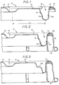
- a metal cover 11 here with a generally circular outline and seen in a radial section.
- This cover consists of a central wall 12 and an outer rolled edge 13 shaped to fit the edge of the container opening (not shown), conventionally a metal bucket more particularly intended to contain dangerous or corrosive materials .
- the rolled edge houses a seal 14, made of elastomeric material. This is housed inside the annular space open downwards (in the position of use) defined by said rolled edge.
- the cover also includes a peripheral annular groove 15, stamped so as to open on the upper face of the cover.
- the central wall 12 is generally situated in a plane close to that which contains the top of the rolled edge 13. In FIG. 1, the distance h which separates these two planes has been indicated. It can be seen that the plane of the central wall is only a few millimeters (about 2 mm for a cover 30 cm in diameter) below the top of the rolled edge 13. In this way, the annular groove 15 which s 'extends between the rolled edge and the central wall has two side walls 15 a , 15 b of neighboring heights and the inner side wall 15 b has an annular stiffening shoulder 16.
- the outer side wall 15 a is in the extension direct from the rolled edge 13. In other words, the wall 15 a also constitutes the inner lateral wall of said rolled edge 13.
- the wall 15 a is substantially frustoconical while the wall 15 b comprises two frustoconical portions separated by the stiffening shoulder.
- the central wall 12 has an annular groove 17 of depth less than that of said peripheral annular groove 15.
- This groove 17 is here concentric with the groove 15; in all cases, it extends at a constant distance d therefrom. Here it has a substantially trapezoidal radial profile.
- the outer rolled edge 13 is shaped to cooperate with a not shown clamp.
- a necklace is well known in the art, it is a kind of cut ring whose two opposite ends are joined by a clamping mechanism with circumferential action, such as a screw-nut system or a lever system.
- FIG. 2 is identical to that of FIG. 1, except as regards the shape of the outer rolled edge.
- the other structural features of this cover will therefore not be described again; they bear the same reference numbers.
- the outer rolled edge 13 a is provided with a crenellated outer skirt 19 defining crimping lugs 20 intended to be assembled to a rounded rim of the container (not shown) generally materialized by another roll.
- the crimping of the lid is effected by pushing back the tabs 20, radially inwards, which has the effect of causing the compression of the seal 14 against the surface of the rim of the container. .
- the shape of the peripheral annular groove makes it possible to significantly improve the performance of the cover during the fall test (fall height 1.20 m). Indeed, in the region of the impact, the side walls of the groove come closer to the wall of the container instead of moving away from it, which avoids decompression of the seal 14 ensuring the seal.
- this cover makes it possible to increase the volume available inside the container since the central wall 12 is almost at the same level as the top of the rolled edge 13.
Landscapes
- Engineering & Computer Science (AREA)
- Mechanical Engineering (AREA)
- Manufacture Of Alloys Or Alloy Compounds (AREA)
- Closures For Containers (AREA)
- Glass Compositions (AREA)
- Pressure Vessels And Lids Thereof (AREA)
- Superconductors And Manufacturing Methods Therefor (AREA)
- Insulated Conductors (AREA)
- Packages (AREA)
Description
- L'invention se rapporte à un couvercle métallique selon le préambule de la revendication 1 pour un récipient étanche, comme par exemple un seau métallique destiné à contenir des matières dangereuses; elle concerne plus particulièrement une forme nouvelle d'un tel couvercle permettant d'en améliorer sensiblement la résistance mécanique, particulièrement la tenue à la pression interne d'un recipient fermé par un tel couvercle.
- Un couvercle métallique connu, du genre indiqué ci-dessus comprend une paroi centrale située en contrebas du sommet d'un bord roulé extérieur conformé pour s'adapter au bord du récipient. La paroi centrale se raccorde souvent au bord roulé par une gorge annulaire, néanmoins séparée radialement de ce dernier. Le bord roulé extérieur peut être fixé au bord du recipient au moyen d'un collier de serrage, notamment pour les récipients de grande contenance. 11 peut aussi être pourvu d'une jupe extérieure crénelée définissant des pattes de sertissage destinées à
- Les documents GB-A-476980 (correspondant au préambule de la revendication 1) et DE-A-1 432 106 décrivent des couvercles métalliques à bord roulé extérieur dont la paroi centrale est globalement située dans un plan voisin de celui qui contient le sommet du bord roulé, définissant ainsi une gorge annulaire périphérique.
- La résistance mécanique et l'étanchéité globale d'un tel récipient fermé par un couvercle de ce genre sont appréciées par un certain nombre de tests normalisés, pratiqués dans des conditions prédéterminées. L'un d'eux est connu sous le nom de test de pression interne et consiste à augmenter progressivement la pression dans un récipient fermé par un tel couvercle, jusqu'à ce qu'une fuite soit détectée. On note alors la pression maximum qui a été atteinte.
- L'invention concerne un nouveau type de couvercle métallique présentant des particularités de structures améliorant ses caractéristiques mécaniques globales et notamment ses performances au test de pression interne.
- L'invention concerne un couvercle métallique pour récipient étanche tel que par exemple un seau métallique, du type comportant une paroi centrale, un bord roulé extérieur conformé pour s'adapter au bord dudit récipient et une gorge annulaire périphérique entre ledit bord roulé et ladite paroi centrale, cette dernière étant globalement située dans un plan voisin de celui qui contient le sommet dudit bord roulé de façon à définir une gorge annulaire comportant deux parois latérales de hauteurs voisines, caractérisé en ce que ladite paroi latérale intérieure de cette gorge comporte un épaulement annulaire de raidissement.
- Selon une autre caractéristique remarquable, la paroi latérale extérieure de la gorge annulaire est dans le prolongement direct du bord roulé extérieur.
- A titre indicatif, avec un couvercle de ce type d'un diamètre de 30 cm environ, on parvient à pousser le test de pression interne au-dessus de 100 kPa, ce qui correspond à une classe dite "danger 2" (selon les réglementations ONU, IMDG "International Maritime code for transport of Dangerous Goods", IATA "International Air Transport Association", RID "Accord Européen relatif au transport International des marchandises Dangereuses par Rail", ADR "Accord Européen relatif au transport International des marchandises Dangereuses par Route", RTMD "Règlement français pour le Transport des Matières Dangereuses").
- L'invention sera mieux comprise et d'autres avantages de celle-ci apparaîtront plus clairement à la lumière de la description qui va suivre de deux modes de réalisation d'un couvercle métallique conforme à son principe, donnée uniquement à titre d'exemple et faite en référence aux dessins annexés dans lesquels:
- la figure 1 est une vue partielle en coupe radiale d'un premier mode de réalisation d'un couvercle métallique conforme à l'invention;
- la figure 2 est une vue analogue à la figure 1, illustrant une variante; et
- la figure 3 est une vue analogue à la figure 2, illustrant une autre variante.
- En se référant plus particulièrement à la figure 1, on a représenté partiellement un couvercle métallique 11, ici à contour globalement circulaire et vu suivant une coupe radiale. Ce couvercle se compose d'une paroi centrale 12 et d'un bord roulé extérieur 13 conformé pour s'adapter au bord de l'ouverture du récipient (non représenté), classiquement un seau métallique plus particulièrement destiné à renfermer des matières dangereuses ou corrosives. Le bord roulé abrite un joint 14, en matériau élastomère. Celui-ci se trouve logé à l'intérieur de l'espace annulaire ouvert vers le bas (en position d'utilisation) défini par ledit bord roulé. Le couvercle comporte également une gorge annulaire périphérique 15, emboutie de façon à s'ouvrir sur la face supérieure du couvercle.
- La paroi centrale 12 est globalement située dans un plan voisin de celui qui contient le sommet du bord roulé 13. Sur la figure 1, on a indiqué la distance h qui sépare ces deux plans. On voit que le plan de la paroi centrale n'est qu'à quelques millimètres (2 mm environ pour un couvercle de 30 cm de diamètre) au-dessous du sommet du bord roulé 13. De cette façon, la gorge annulaire 15 qui s'étend entre le bord roulé et la paroi centrale comporte deux parois latérales 15a, 15b de hauteurs voisines et la paroi latérale intérieure 15b comporte un épaulement de raidissement annulaire 16. La paroi latérale extérieure 15a est quant à elle dans le prolongement direct du bord roulé 13. Autrement dit, la paroi 15a constitue aussi la paroi latérale intérieure dudit bord roulé 13. La paroi 15a est sensiblement tronconique tandis que la paroi 15b comporte deux portions tronconiques séparées par l'épaulement de raidissement.
- De plus, la paroi centrale 12 comporte une gorge annulaire 17 de profondeur inférieure à celle de ladite gorge annulaire périphérique 15. Cette gorge 17 est ici concentrique à la gorge 15; dans tous les cas de figure, elle s'étend à une distance constante d de celle-ci. Elle a ici un profil radial sensiblement trapézoïdal.
- Le bord roulé extérieur 13 est conformé pour coopérer avec un collier de serrage non représenté. Un tel collier est bien connu dans la technique, il s'agit d'une sorte d'anneau coupé dont les deux extrémités en regard sont réunies par un mécanisme de serrage à action circonférentielle, tel qu'un système vis-écrou ou un système de levier.
- Le mode de réalisation de la figure 2 est identique à celui de la figure 1, sauf en ce qui concerne la forme du bord roulé extérieur. Les autres particularités de structure de ce couvercle ne seront donc pas décrites à nouveau; elles portent les mêmes références numériques. Le bord roulé extérieur 13a est pourvu d'une jupe extérieure crénelée 19 définissant des pattes de sertissage 20 prévues pour être assemblées à un rebord arrondi du récipient (non représenté) généralement matérialisé par un autre roulé. Lorsque le couvercle est en place sur le rebord du récipient, le sertissage du couvercle s'effectue par refoulement des pattes 20, radialement vers l'intérieur, ce qui a pour effet de provoquer la compression du joint 14 contre la surface du rebord du récipient.
- Avec la structure de couvercle qui vient d'être décrite, on a constaté qu'au test de la pression interne, la déformation du couvercle se fait régulièrement et progressivement par l'apparition d'un bombé sans formation de pli radial localisé, phénomène qui précipite ordinairement l'apparition de la fuite. Avec la structure de couvercle ci-dessus, les performances au test de pression hydraulique ont pu être portées, pour un type de couvercle donné, de 0,7 à 1,2 bars, toutes choses égales par ailleurs.
- De plus, la forme de la gorge annulaire périphérique permet d'améliorer notablement la performance du couvercle lors du test de chute (hauteur de chute 1,20 m). En effet, dans la région de l'impact, les parois latérales de la gorge se rapprochent de la paroi du récipient au lieu de s'en éloigner, ce qui évite la décompression du joint 14 assurant l'étanchéité.
- Il est en outre à noter que la forme même de ce couvercle permet d'augmenter le volume disponible à l'intérieur du récipient puisque la paroi centrale 12 se trouve pratiquement au même niveau que le sommet du bord roulé 13.
- Sur la figure 3, les éléments analogues portent les mêmes références numériques que dans les modes de réalisation précédents et toutes ces particularités de structure communes ne seront pas décrites à nouveau. On remarque cependant que l'épaulement de raidissement annulaire 16a est beaucoup plus accentué que dans les modes de réalisation précédents et se situent approximativement dans un plan parallèle à celui de la paroi centrale 12 du couvercle. On a découvert que cette forme particulière était propre à améliorer encore les performances aux tests indiqués ci-dessus. Toutes choses égales par ailleurs, on peut ainsi réduire l'épaisseur de tôle de plus de 15%.
- En outre, on a également trouvé que, dans le cas des modes de réalisation des figures 2 et 3, il était avantageux de déterminer le nombre de pattes de sertissage 20 de façon qu'elles deviennent jointives circonférentiellement après mise en place du couvercle et repliement desdites pattes. Les pattes ainsi serrées les unes à côté des autres créent une sorte de "bague" autour du roulé délimitant l'ouverture du récipient.
- A titre d'exemple, l'application de ce principe conduit, pour un couvercle de 32 cm de diamètre environ à choisir un nombre de pattes de sertissage égal à 15, occupant chacune un secteur de 24°, alors que le nombre de pattes était traditionnellement et arbitrairement fixé à 18.
Claims (7)
- Couvercle métallique pour récipient étanche tel qu'un seau métallique, du type comportant une paroi centrale (12), un bord roulé extérieur (13) conformé pour s'adapter au bord dudit récipient et une gorge annulaire périphérique (15) entre ledit bord roulé et ladite paroi centrale (12), cette dernière étant globalement située dans un plan voisin de celui qui contient le sommet dudit bord roulé (13), de façon à définir une gorge annulaire (15) comportant deux parois latérales (15a, 15b) de hauteurs voisines, caractérisé en ce que la paroi latérale intérieure (15b) comporte un épaulement de raidissement annulaire (16).
- Couvercle métallique selon la revendication 1, caracérisé en ce que la paroi latérale extérieure (15a) de la gorge annulaire périphérique (15) est dans le prolongement dudit bord roulé (13).
- Couvercle métallique selon la revendication 1 ou 2, caractérisé en ce que ladite paroi centrale (12) comporte une gorge annulaire (17) de profondeur inférieure à celle de ladite gorge annulaire périphérique (15) et s'étendant à distance constante (d) de celle-ci.
- Couvercle métallique selon l'une des revendications précédentes, caractérisé en ce que ledit bord roulé extérieur (13) est conformé pour coopérer avec un collier de serrage.
- Couvercle métallique selon l'une des revendications 1 à 3, caractérisé en ce que le bord roulé extérieur (13a) est pourvu d'une jupe extérieure crénelée (19) définissant des pattes de sertissage (20).
- Couvercle métallique selon la revendication 5, caractérisé en ce que le nombre des pattes de sertissage (20) est déterminé de façon qu'elles deviennent jointives circonférentiellement après mise en place du couvercle et repliement desdites pattes.
- Couvercle métallique selon l'une des revendications précédentes, caractérisé en ce que ledit épaulement de raidissement annulaire (16a) se situe approximativement dans un plan parallèle à celui de ladite paroi centrale (12).
Applications Claiming Priority (2)
| Application Number | Priority Date | Filing Date | Title |
|---|---|---|---|
| FR9015672 | 1990-12-14 | ||
| FR9015672A FR2670469B1 (fr) | 1990-12-14 | 1990-12-14 | Couvercle metallique a haute resistance mecanique. |
Publications (2)
| Publication Number | Publication Date |
|---|---|
| EP0490735A1 EP0490735A1 (fr) | 1992-06-17 |
| EP0490735B1 true EP0490735B1 (fr) | 1994-06-08 |
Family
ID=9403243
Family Applications (1)
| Application Number | Title | Priority Date | Filing Date |
|---|---|---|---|
| EP91403300A Expired - Lifetime EP0490735B1 (fr) | 1990-12-14 | 1991-12-06 | Couvercle métallique à haute résistance mécanique |
Country Status (9)
| Country | Link |
|---|---|
| EP (1) | EP0490735B1 (fr) |
| AT (1) | ATE106831T1 (fr) |
| AU (1) | AU8976191A (fr) |
| DE (1) | DE69102408T2 (fr) |
| DK (1) | DK0490735T3 (fr) |
| ES (1) | ES2059089T3 (fr) |
| FI (1) | FI94117C (fr) |
| FR (1) | FR2670469B1 (fr) |
| NO (1) | NO179635C (fr) |
Family Cites Families (4)
| Publication number | Priority date | Publication date | Assignee | Title |
|---|---|---|---|---|
| GB417906A (en) * | 1934-01-11 | 1934-10-15 | Robert Dette | Lid for boxes and like containers especially for preserve tins |
| GB476980A (en) * | 1936-01-31 | 1937-12-20 | Crown Cork & Seal Co | Improvements in containers such as cans and the like |
| DE1432284A1 (de) * | 1961-03-10 | 1968-12-19 | Gruss Blechwaren | Behaelter mit hermetischem bzw. absolut dichtem Verschluss fuer UEberdruecke oder Unterdruecke unter Verwendung von Sicken und ringfoermiger Dichtung,die sich ohne Beschaedigung des Deckels leicht oeffnen und bei teilweiser Entnahme des Fuellgutes wieder verschliessen lassen |
| US3383006A (en) * | 1966-03-04 | 1968-05-14 | Elmer J. Knize | Can or container and the lid therefor |
-
1990
- 1990-12-14 FR FR9015672A patent/FR2670469B1/fr not_active Expired - Fee Related
-
1991
- 1991-12-06 AT AT91403300T patent/ATE106831T1/de not_active IP Right Cessation
- 1991-12-06 EP EP91403300A patent/EP0490735B1/fr not_active Expired - Lifetime
- 1991-12-06 ES ES91403300T patent/ES2059089T3/es not_active Expired - Lifetime
- 1991-12-06 DK DK91403300.6T patent/DK0490735T3/da active
- 1991-12-06 DE DE69102408T patent/DE69102408T2/de not_active Expired - Fee Related
- 1991-12-13 AU AU89761/91A patent/AU8976191A/en not_active Abandoned
- 1991-12-13 FI FI915885A patent/FI94117C/fi active
- 1991-12-13 NO NO914916A patent/NO179635C/no unknown
Also Published As
| Publication number | Publication date |
|---|---|
| NO179635C (no) | 1996-11-20 |
| FI94117B (fi) | 1995-04-13 |
| DE69102408T2 (de) | 1994-10-13 |
| FI915885A0 (fi) | 1991-12-13 |
| NO179635B (no) | 1996-08-12 |
| AU8976191A (en) | 1992-06-18 |
| ATE106831T1 (de) | 1994-06-15 |
| DK0490735T3 (da) | 1994-10-10 |
| FI94117C (fi) | 1995-07-25 |
| DE69102408D1 (de) | 1994-07-14 |
| EP0490735A1 (fr) | 1992-06-17 |
| NO914916L (no) | 1992-06-15 |
| ES2059089T3 (es) | 1994-11-01 |
| FR2670469A1 (fr) | 1992-06-19 |
| FR2670469B1 (fr) | 1993-07-30 |
| NO914916D0 (no) | 1991-12-13 |
| FI915885L (fi) | 1992-06-15 |
Similar Documents
| Publication | Publication Date | Title |
|---|---|---|
| EP1104253B1 (fr) | Joint indexe pour autocuiseur, et autocuiseur equipe d'un tel joint | |
| FR2471325A1 (fr) | Pot en matiere plastique a peinture, appareil de demoulage dudit pot et son procede de mise en oeuvre | |
| EP1206357B1 (fr) | Ensemble d'une jante et d'un appui de soutien | |
| WO2011077037A2 (fr) | Joint pour autocuiseur comportant une jupe souple pourvue d'encoches | |
| EP1691649B1 (fr) | Recipient de cuisson sous pression pourvu d'un couvercle rentrant a deformation controlee et couvercle correspondant | |
| EP0779488B1 (fr) | Echangeur de chaleur, notamment pour véhicule automobile | |
| EP0567374B1 (fr) | Capsule distributrice pour produits liquides ou pâteux | |
| EP0383745B1 (fr) | Récipient | |
| WO1996026866A1 (fr) | Accessoire tubulaire opercule pour boite de boisson jetable | |
| FR2495699A1 (fr) | Pompe a membrane | |
| EP0490735A1 (fr) | Couvercle métallique à haute résistance mécanique | |
| EP0507704B1 (fr) | Boîtier distributeur métallique à coupelle de valve sertie extérieurement | |
| EP0370855A1 (fr) | Dispositif de verrouillage et de déverrouillage de deux éléments d'un projectile, notamment d'un pot de parachute | |
| EP0474544A1 (fr) | Dispositif de renforcement d'emballage métallique | |
| EP0844190B1 (fr) | Bouchon à charnière pour bouteille | |
| EP3782168B1 (fr) | Emballage pour le transport et/ou l'entreposage de matieres radioactives presentant une conception facilitant la manutention de l'ensemble de matieres radioactives | |
| EP0415819B1 (fr) | Couvercle métallique pour récipient étanche | |
| BE1009404A3 (fr) | Collier de serrage pour fut metallique et fut equipe de ce collier. | |
| WO2019129975A1 (fr) | Emballage de transport et/ou d'entreposage de matieres radioactives presentant des moyens ameliores de maintien de capot amortisseur | |
| EP0690001B1 (fr) | Fût métallique à ouverture totale | |
| FR2719986A1 (fr) | Autocuiseur. | |
| EP0900745A1 (fr) | Récipient en verre destiné à la conserve de produits alimentaires | |
| FR3134997A1 (fr) | Pompe | |
| FR2564802A1 (fr) | Dispositif d'obturation temporaire, pour recipient a col | |
| BE495339A (fr) |
Legal Events
| Date | Code | Title | Description |
|---|---|---|---|
| PUAI | Public reference made under article 153(3) epc to a published international application that has entered the european phase |
Free format text: ORIGINAL CODE: 0009012 |
|
| AK | Designated contracting states |
Kind code of ref document: A1 Designated state(s): AT BE CH DE DK ES FR GB GR IT LI LU NL SE |
|
| 17P | Request for examination filed |
Effective date: 19920710 |
|
| 17Q | First examination report despatched |
Effective date: 19930111 |
|
| RAP3 | Party data changed (applicant data changed or rights of an application transferred) |
Owner name: CARNAUDMETALBOX |
|
| GRAA | (expected) grant |
Free format text: ORIGINAL CODE: 0009210 |
|
| AK | Designated contracting states |
Kind code of ref document: B1 Designated state(s): AT BE CH DE DK ES FR GB GR IT LI LU NL SE |
|
| REF | Corresponds to: |
Ref document number: 106831 Country of ref document: AT Date of ref document: 19940615 Kind code of ref document: T |
|
| GBT | Gb: translation of ep patent filed (gb section 77(6)(a)/1977) |
Effective date: 19940614 |
|
| REF | Corresponds to: |
Ref document number: 69102408 Country of ref document: DE Date of ref document: 19940714 |
|
| ITF | It: translation for a ep patent filed | ||
| REG | Reference to a national code |
Ref country code: DK Ref legal event code: T3 |
|
| REG | Reference to a national code |
Ref country code: GR Ref legal event code: FG4A Free format text: 3013003 |
|
| REG | Reference to a national code |
Ref country code: ES Ref legal event code: FG2A Ref document number: 2059089 Country of ref document: ES Kind code of ref document: T3 |
|
| EAL | Se: european patent in force in sweden |
Ref document number: 91403300.6 |
|
| PLBI | Opposition filed |
Free format text: ORIGINAL CODE: 0009260 |
|
| 26 | Opposition filed |
Opponent name: KARL HUBER VERPACKUNGEN GMBH & CO. Effective date: 19950308 |
|
| NLR1 | Nl: opposition has been filed with the epo |
Opponent name: KARL HUBER VERPACKUNGEN GMBH & CO. |
|
| PLBO | Opposition rejected |
Free format text: ORIGINAL CODE: EPIDOS REJO |
|
| PLBN | Opposition rejected |
Free format text: ORIGINAL CODE: 0009273 |
|
| STAA | Information on the status of an ep patent application or granted ep patent |
Free format text: STATUS: OPPOSITION REJECTED |
|
| 27O | Opposition rejected |
Effective date: 19960406 |
|
| NLR2 | Nl: decision of opposition | ||
| PGFP | Annual fee paid to national office [announced via postgrant information from national office to epo] |
Ref country code: DK Payment date: 19971111 Year of fee payment: 7 |
|
| PGFP | Annual fee paid to national office [announced via postgrant information from national office to epo] |
Ref country code: AT Payment date: 19971113 Year of fee payment: 7 |
|
| PGFP | Annual fee paid to national office [announced via postgrant information from national office to epo] |
Ref country code: SE Payment date: 19971117 Year of fee payment: 7 |
|
| PGFP | Annual fee paid to national office [announced via postgrant information from national office to epo] |
Ref country code: GR Payment date: 19971125 Year of fee payment: 7 |
|
| PGFP | Annual fee paid to national office [announced via postgrant information from national office to epo] |
Ref country code: CH Payment date: 19971202 Year of fee payment: 7 |
|
| PGFP | Annual fee paid to national office [announced via postgrant information from national office to epo] |
Ref country code: LU Payment date: 19980303 Year of fee payment: 7 |
|
| PG25 | Lapsed in a contracting state [announced via postgrant information from national office to epo] |
Ref country code: LU Free format text: LAPSE BECAUSE OF NON-PAYMENT OF DUE FEES Effective date: 19981206 Ref country code: DK Free format text: LAPSE BECAUSE OF NON-PAYMENT OF DUE FEES Effective date: 19981206 Ref country code: AT Free format text: LAPSE BECAUSE OF NON-PAYMENT OF DUE FEES Effective date: 19981206 |
|
| PG25 | Lapsed in a contracting state [announced via postgrant information from national office to epo] |
Ref country code: SE Free format text: LAPSE BECAUSE OF NON-PAYMENT OF DUE FEES Effective date: 19981207 |
|
| PG25 | Lapsed in a contracting state [announced via postgrant information from national office to epo] |
Ref country code: LI Free format text: LAPSE BECAUSE OF NON-PAYMENT OF DUE FEES Effective date: 19981231 Ref country code: GR Free format text: LAPSE BECAUSE OF NON-PAYMENT OF DUE FEES Effective date: 19981231 Ref country code: CH Free format text: LAPSE BECAUSE OF NON-PAYMENT OF DUE FEES Effective date: 19981231 |
|
| REG | Reference to a national code |
Ref country code: CH Ref legal event code: PL |
|
| PGFP | Annual fee paid to national office [announced via postgrant information from national office to epo] |
Ref country code: FR Payment date: 19991213 Year of fee payment: 9 |
|
| PGFP | Annual fee paid to national office [announced via postgrant information from national office to epo] |
Ref country code: GB Payment date: 19991217 Year of fee payment: 9 |
|
| PGFP | Annual fee paid to national office [announced via postgrant information from national office to epo] |
Ref country code: NL Payment date: 19991223 Year of fee payment: 9 |
|
| PGFP | Annual fee paid to national office [announced via postgrant information from national office to epo] |
Ref country code: DE Payment date: 19991227 Year of fee payment: 9 |
|
| PGFP | Annual fee paid to national office [announced via postgrant information from national office to epo] |
Ref country code: ES Payment date: 19991231 Year of fee payment: 9 |
|
| PGFP | Annual fee paid to national office [announced via postgrant information from national office to epo] |
Ref country code: BE Payment date: 20000107 Year of fee payment: 9 |
|
| PG25 | Lapsed in a contracting state [announced via postgrant information from national office to epo] |
Ref country code: GB Free format text: LAPSE BECAUSE OF NON-PAYMENT OF DUE FEES Effective date: 20001206 |
|
| PG25 | Lapsed in a contracting state [announced via postgrant information from national office to epo] |
Ref country code: BE Free format text: LAPSE BECAUSE OF NON-PAYMENT OF DUE FEES Effective date: 20001231 |
|
| REG | Reference to a national code |
Ref country code: DK Ref legal event code: EBP |
|
| BERE | Be: lapsed |
Owner name: CARNAUDMETALBOX Effective date: 20001231 |
|
| PG25 | Lapsed in a contracting state [announced via postgrant information from national office to epo] |
Ref country code: NL Free format text: LAPSE BECAUSE OF NON-PAYMENT OF DUE FEES Effective date: 20010701 |
|
| GBPC | Gb: european patent ceased through non-payment of renewal fee |
Effective date: 20001206 |
|
| PG25 | Lapsed in a contracting state [announced via postgrant information from national office to epo] |
Ref country code: FR Free format text: LAPSE BECAUSE OF NON-PAYMENT OF DUE FEES Effective date: 20010831 |
|
| NLV4 | Nl: lapsed or anulled due to non-payment of the annual fee |
Effective date: 20010701 |
|
| REG | Reference to a national code |
Ref country code: FR Ref legal event code: ST |
|
| PG25 | Lapsed in a contracting state [announced via postgrant information from national office to epo] |
Ref country code: DE Free format text: LAPSE BECAUSE OF NON-PAYMENT OF DUE FEES Effective date: 20011002 |
|
| PG25 | Lapsed in a contracting state [announced via postgrant information from national office to epo] |
Ref country code: ES Free format text: LAPSE BECAUSE OF NON-PAYMENT OF DUE FEES Effective date: 20011207 |
|
| REG | Reference to a national code |
Ref country code: ES Ref legal event code: FD2A Effective date: 20020112 |
|
| PG25 | Lapsed in a contracting state [announced via postgrant information from national office to epo] |
Ref country code: IT Free format text: LAPSE BECAUSE OF NON-PAYMENT OF DUE FEES Effective date: 20051206 |