EP0489980B1 - Halterungsvorrichtung für das Spulengehäuse bei einer Nähmaschine - Google Patents
Halterungsvorrichtung für das Spulengehäuse bei einer Nähmaschine Download PDFInfo
- Publication number
- EP0489980B1 EP0489980B1 EP90203282A EP90203282A EP0489980B1 EP 0489980 B1 EP0489980 B1 EP 0489980B1 EP 90203282 A EP90203282 A EP 90203282A EP 90203282 A EP90203282 A EP 90203282A EP 0489980 B1 EP0489980 B1 EP 0489980B1
- Authority
- EP
- European Patent Office
- Prior art keywords
- bobbin
- case holder
- bobbin case
- body member
- thread
- Prior art date
- Legal status (The legal status is an assumption and is not a legal conclusion. Google has not performed a legal analysis and makes no representation as to the accuracy of the status listed.)
- Expired - Lifetime
Links
- 230000005291 magnetic effect Effects 0.000 claims description 5
- 239000000696 magnetic material Substances 0.000 claims description 4
- 239000003302 ferromagnetic material Substances 0.000 claims description 3
- 238000009958 sewing Methods 0.000 description 8
- 230000000717 retained effect Effects 0.000 description 3
- XEEYBQQBJWHFJM-UHFFFAOYSA-N Iron Chemical compound [Fe] XEEYBQQBJWHFJM-UHFFFAOYSA-N 0.000 description 2
- 230000003247 decreasing effect Effects 0.000 description 2
- 238000006073 displacement reaction Methods 0.000 description 2
- 230000015572 biosynthetic process Effects 0.000 description 1
- 238000010276 construction Methods 0.000 description 1
- 238000009434 installation Methods 0.000 description 1
- 229910052742 iron Inorganic materials 0.000 description 1
Images


Classifications
-
- D—TEXTILES; PAPER
- D05—SEWING; EMBROIDERING; TUFTING
- D05B—SEWING
- D05B57/00—Loop takers, e.g. loopers
- D05B57/08—Loop takers, e.g. loopers for lock-stitch sewing machines
- D05B57/10—Shuttles
- D05B57/20—Shuttles with bobbin casings held by magnetic forces
-
- D—TEXTILES; PAPER
- D05—SEWING; EMBROIDERING; TUFTING
- D05B—SEWING
- D05B57/00—Loop takers, e.g. loopers
- D05B57/08—Loop takers, e.g. loopers for lock-stitch sewing machines
- D05B57/10—Shuttles
- D05B57/14—Shuttles with rotary hooks
Definitions
- the invention relates to a bobbin holding structure for detachably mounting a bobbin in a bobbin case holder rotatably mounted but axially locked in a rotating hook of a looptaker said bobbin case holder including a bottom of ferromagnetic material and having an open end.
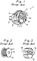
- FIG. 1 is a perspective view of a typical prior art structure
- Fig. 2 is a perspective view of a bobbin 5
- Fig. 3 is a perspective view of a bobbin case 6 where the bobbin case 6 is shown partially cut away.
- a horizontal axis full rotary looptaker 1 provided in a lock stitch sewing machine includes a rotating hook 3 driven by a rotary shaft 2 to rotate around a horizontal axis and a bobbin case holder 4 housed in the rotating hook 3.
- Bobbin case 6 housing a bobbin 5 fits in the bobbin case holder 4.
- the bobbin case holder 4 is prevented from rotating by a rotation stopper member 7.
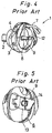
- Fig. 4 is a perspective view of the horizontal axis full rotary looptaker 1 with the bobbin 5 and the bobbin case 6 removed therefrom.
- Fig. 5 is a partially enlarged perspective view of the bobbin case 6.
- a stud 9 projects perpendicularly from a bottom 8 of the bobbin case holder 4 to an open end thereof.
- a hollow shaft 10 of straight cylindrical shape is positioned within the bobbin case 6.
- the hollow shaft 10 is inserted through a central hole 11 of the bobbin 5, and the bobbin 5 is housed in the bobbin case 6.
- the bobbin case 6 which houses the bobbin 5 is housed in the bobbin case holder 4 with the stud 9 inserted through the hollow shaft 10.
- a locking piece 13 which is provided on the bobbin case 6 is locked in a locking groove 12 which is formed at a free end of the stud 9, thereby locking the bobbin case 6 in the bobbin case holder 4.
- the bobbin 5 is retained in the bobbin case holder 4 by the bobbin case 6.
- a pivotable flap 14 is operated to release the lock between the locking piece 13 and the stud 9 and the bobbin case 6 is removed from the bobbin case holder 4 and the bobbin 5 is removed from the bobbin case 6.
- a bobbin holding structure which is characterized by
- this bobbin holding member When this bobbin holding member is installed in the bobbin case holder, the body member is disposed in the direction of the diameter of the bobbin case holder and the free end of the bobbin case holder fits in the slot, thereby preventing displacement in the direction of the diameter and ensuring the position of the body with respect to the bobbin case holder.
- the tip of the shaft extends to adjacent the bottom of the bobbin case holder, and the attraction member provided at the tip magnetically adheres to the bottom, thus retaining the bobbin in the bobbin case holder.
- the body is equipped with a bobbin thread tensioner spring, the bobbin thread lead extending from the bobbin, retained in the bobbin case holder can be properly tensioned, thereby enabling the formation of stitches of good quality without allowing slack in the thread.
- the bobbin holding structure of the invention makes possible the replacement of only the bobbin case holder unlike the rotating hooks of the prior art, and therefore can be employed with a wide range of rotating hooks in existing sewing machines.
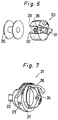
- Fig.6 is a perspective view of a bobbin case or bobbin holding member 20 illustrative of an embodiment of the invention
- Fig.7 is a perspective view of a horizontal axis full rotary looptaker 21 which may be equipped with the bobbin holding member 20.
- the bobbin holding member 20 is shown partially cut away.
- the horizontal axis full rotary looptaker 21 to be installed in a lock stitch sewing machine is provided with a rotating hook 23 fixed to a rotary shaft 22 which is driven to rotate about a horizontal rotary axis.
- a bobbin case holder 24 made of a ferromagnetic material such as iron is housed in the rotating hook 23, and the bobbin holding member 20 with a bobbin 25 housed therein is installed in the bobbin case holder 24.
- a rotation stopper 26 prevents the bobbin case holder 24 from rotating, when the rotating hook 23 is rotated about the rotary axis thereof.
- the bottom 27 of the bobbin case holder 24 is flat because it is not necessary to provide a stud 9 as required in the above described prior art structure.
- the bobbin holding member 20 has a cylindrically shaped shaft 28 which extends along a center center axis 11 thereof. Formed at the tip of the shaft 28 is a recess 29 having fixed therein an attraction member 30 made of a magnetic material e.g. a permanent magnet.
- an attraction member 30 made of a magnetic material e.g. a permanent magnet.
- installation of a cylindrical attraction member in a hollow shaft 10 of the conventional bobbin case 6 makes it possible to use the conventional bobbin case holder 4.
- the invention may widely be employed with existing rotating hooks.
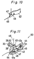
- Fig.8 is a perspective view of the bobbin holding member 40 installed in the horizontal axis full rotary looptaker 21 according to a first embodiment of the invention.
- Fig.9 is an enlarged perspective view of the bobbin holding member 40.
- Fig.10 is a partially enlarged perspective view of a bobbin thread tensioner spring 43. Parts which correspond to those of the embodiment mentioned above are designated by like reference numerals.
- the bobbin holding member 40 includes a body 41 in the form of an elongated bar which is installed at the end face 24a of the bobbin case holder 24 at an axially open end and extends in the direction of the diameter thereof, and a shaft 28 extending perpendicularly from the center of the body 41 in axial direction of the bobbin case holder 24.
- the body 41 has at opposite ends thereof fitting slots 42a, 42b to accommodate the end face 24a of the bobbin case holder 24.
- Bobbin thread tensioner 43 has a curved plate shape and has a base end section thereof fixed to body 41 by a screw 44.
- An adjustment screw 45 freely passes axially through the center of the bobbin thread tensioner spring 43 and is threaded into a screw hole formed in the body 41.
- a pressurizing portion 47 which makes elastic contact with one side 41a of the body 41 and pressurizes a bobbin thread 46.
- a bobbin thread guiding slot 48 is formed in portion 47, as shown in Fig.10. The bobbin thread 46 is passed through the bobbin thread guiding slot 48, and is elastically pressed against the side face 41a by the pressurizing portion 47.
- the adjustment screw 45 By turning the adjustment screw 45 in opposite directions, the force acting on the bobbin thread can be adjusted. Therefore, it is possible to apply a proper tension, by the rotary action of the rotating hook 23, to the bobbin thread 46 removed from the bobbin 25, thereby ensuring a sewing operation conducted with a desired thread tension.
- Fig.11 is a perspective view of a bobbin holding member 60 illustrative of a second embodiment of the invention.
- a body 61 of the bobbin holding member 60 has integrally formed therewith a bobbin thread guiding member 62.
- the bobbin thread guiding member 62 has formed therein a notch 63 through which fits the bobbin thread 46.
- the bobbin thread 46 removed from the bobbin 25 passes through the bobbin thread guiding slot 48, is elastically pressed by the pressurizing portion 47 against a side face 61a of the body 61, and is passed through the notch 63.
- the bobbin holding member 60 may be magnetically attracted to the end face 24a of the bobbin case holder 24 by magnetizing the body 61 adjacent a portion or end 64 thereof. By such arrangement, the bobbin holding member 60 can be installed securely without lateral displacement thereof relative to the end face 24a of the bobbin case holder 24 during a sewing operation.
- Fig.12 is a perspective view of a bobbin holding member 80 illustrative of a third embodiment of the invention.
- a bobbin thread tensioner spring 82 is installed on the base end section of the body 81 of the bobbin holding member 80 by a set screw 83.
- the body 81 is made of a magnetic material so that the bobbin thread tensioner spring 82 is magnetically attracted and thereby presses the bobbin thread 46 against a side face 81a.
- a pressurizing portion 84 Formed at a free end of the bobbin thread tensioner spring 82 is a pressurizing portion 84 having formed therein a bobbin thread guiding slot 85.
- a mounting section 87 Formed between the base end section and the free end section of the bobbin thread tensioner spring 82 is a mounting section 87 through which is threaded an adjustment screw 86.
- a tip end of the screw 86 is in contact with a top face 81b of the body 81.
Landscapes
- Engineering & Computer Science (AREA)
- Textile Engineering (AREA)
- Sewing Machines And Sewing (AREA)
Claims (1)
- Spulenhalteanordnung zur abnehmbaren Anbringung einer Spule (25) in einem Spulengehäusehalter (24), der in einem Drehhaken (23) eines Schlaufenaufnehmers (1) drehbar angebracht, aber axial gesperrt ist, wobei der genannte Spulengehäusehalter (24) einen Boden (27) aus ferromagnetischem Material umfaßt und ein offenes Ende (24a) aufweist, gekennzeichnet durchein Hauptteil (41, 61, 81) in Form einer Stange, das am offenen Ende (24a) des Spulengehäusehalters (24) anzubringen ist und gegenüberliegende Enden aufweist, wobei mindestens in einem der genannten Enden (42a, 42b) ein Schlitz zur Aufnahme des offenen Endes (24a) des Spulengehäusehalters (24) vorliegt, so daß das genannte Hauptteil, wenn es angebracht ist, sich in Richtung eines Durchmesser des Spulengehäusehalters (24) erstreckt;eine Welle (28), die sich von einer Mitte des Hauptteils (41, 61, 81) senkrecht in axialer Richtung des Spulengehäusehalters (24) erstreckt, wenn das genannte Hauptteil (41, 61, 81) hieran angebracht ist, wobei die genannte Welle (28) eine Endspitze aufweist, die an den Boden (27) des Spulengehäusehalters (24) angrenzend angeordnet ist, wenn das genannte Hauptteil (41, 61, 81) hieran angebracht ist;ein Anziehungsteil (30), das an der Endspitze der genannten Welle (28) angeordnet ist und aus magnetischem Material gebildet ist;wodurch dann, wenn eine Spule (25) im Spulengehäusehalter (24) angebracht ist, die genannte Welle (28) durch eine Mittelöffnung (11) der Spule (25) hindurchgeführt ist, wobei das genannte Hauptteil (41, 61, 81) am offenen Ende (24a) des Spulengehäusehalters (24) angebracht ist und die magnetische Anziehung zwischen dem genannten Anziehungsteil (30) und dem Boden (27) des Spulengehäusehalters (24) das genannten Hauptteil (41, 61, 81) und die Spule (25) im Inneren des Spulengehäusehalters (24) in der Lage hält;eine Spulenfaden-Zugeinrichtungsfeder (43, 82) mit einem Basisende, das am genannten Hauptteil (41, 61, 81) angebracht ist, und einem freien Ende, das elastisch gegen das genannte Hauptteil (41, 61, 81) anliegt, wobei im freien Ende ein Fadenführungsschlitz (48, 85) vorliegt, durch welchen ein Spulenfaden (46) hindurchläuft, wenn eine Spule (25) im Spulengehäusehalter (24) angebracht ist; undein Einstellschraubenteil (45, 86), das sich durch die Spanneinrichtungsfeder (43, 82) hindurch erstreckt, um die genannte Spanneinrichtungsfeder (43, 82) relativ zum genannten Hauptteil (41, 61, 81) zu bewegen und hierdurch die Zugspannung einzustellen, die auf einen Spulenfaden aufgebracht wird, der durch den genannten Fadenführungsschlitz (48, 85) hindurchläuft.
Priority Applications (3)
| Application Number | Priority Date | Filing Date | Title |
|---|---|---|---|
| US07/626,288 US5152236A (en) | 1990-12-13 | 1990-12-12 | Bobbin holding structure |
| EP90203282A EP0489980B1 (de) | 1990-12-13 | 1990-12-13 | Halterungsvorrichtung für das Spulengehäuse bei einer Nähmaschine |
| DE69032163T DE69032163T2 (de) | 1990-12-13 | 1990-12-13 | Halterungsvorrichtung für das Spulengehäuse bei einer Nähmaschine |
Applications Claiming Priority (1)
| Application Number | Priority Date | Filing Date | Title |
|---|---|---|---|
| EP90203282A EP0489980B1 (de) | 1990-12-13 | 1990-12-13 | Halterungsvorrichtung für das Spulengehäuse bei einer Nähmaschine |
Publications (2)
| Publication Number | Publication Date |
|---|---|
| EP0489980A1 EP0489980A1 (de) | 1992-06-17 |
| EP0489980B1 true EP0489980B1 (de) | 1998-03-18 |
Family
ID=8205193
Family Applications (1)
| Application Number | Title | Priority Date | Filing Date |
|---|---|---|---|
| EP90203282A Expired - Lifetime EP0489980B1 (de) | 1990-12-13 | 1990-12-13 | Halterungsvorrichtung für das Spulengehäuse bei einer Nähmaschine |
Country Status (3)
| Country | Link |
|---|---|
| US (1) | US5152236A (de) |
| EP (1) | EP0489980B1 (de) |
| DE (1) | DE69032163T2 (de) |
Families Citing this family (11)
| Publication number | Priority date | Publication date | Assignee | Title |
|---|---|---|---|---|
| US5842431A (en) * | 1997-02-19 | 1998-12-01 | Wu; Chong-Ming | Rotating shuttle and presser plate arrangement |
| US5921192A (en) * | 1998-01-22 | 1999-07-13 | Bakron Corporation | Bobbin assembly with structure for severing improperly routed thread |
| DE19840956C1 (de) * | 1998-09-08 | 2000-02-24 | Gerd Papajewski | Umlaufender Greifer für Doppelsteppstich-Nähmaschinen |
| US6257512B1 (en) * | 1998-12-16 | 2001-07-10 | Fil-Tec, Inc. | Magnetized pre-wound sideless bobbins |
| US6076477A (en) * | 1999-05-21 | 2000-06-20 | Badillo; Paul | Hook system for sewing machine |
| DE10028231B4 (de) * | 2000-05-27 | 2004-11-04 | Philipp Moll | Einrichtung an Näh- oder Stickmaschinen zum Wechseln der Spule für den Greiferfaden |
| US6659384B2 (en) | 2001-08-21 | 2003-12-09 | J. & P. Coats Limited | Pre-wound bobbin with magnetized flange |
| IT1392162B1 (it) | 2008-11-25 | 2012-02-22 | Cerliani | Crochet rotativo per macchina per cucire a punto annodato comprendente mezzi per ridurre la sua rumorosita' |
| WO2010147023A1 (ja) * | 2009-06-16 | 2010-12-23 | エヌエスディ株式会社 | ミシンの下糸張力制御装置及びミシン |
| CH706089A8 (de) * | 2012-02-02 | 2013-10-31 | Bernina Int Ag | Greiferanordnung für eine Nähmaschine. |
| DE102015111580B4 (de) * | 2014-08-05 | 2025-01-02 | Cm Cerliani S.R.L. | Greifer fuer eine Doppelsteppstich-Naehmaschine mit stabiler Spannung des Spulenfadens |
Family Cites Families (11)
| Publication number | Priority date | Publication date | Assignee | Title |
|---|---|---|---|---|
| US1179371A (en) * | 1913-06-12 | 1916-04-11 | Singer Mfg Co | Sewing-machine loop-taker. |
| US1981834A (en) * | 1932-12-29 | 1934-11-20 | Singer Mfg Co | Thread cases for sewing machine loop-takers |
| CH332443A (de) * | 1953-04-09 | 1958-09-15 | Messerschmitt Ag | Greifer für Nähmaschinen |
| US2763227A (en) * | 1953-12-30 | 1956-09-18 | Birtman Electric Co | Bobbin case |
| GB1000481A (en) * | 1960-10-13 | 1965-08-04 | British United Shoe Machinery | Improvements in or relating to sewing machines |
| US3051108A (en) * | 1961-08-24 | 1962-08-28 | Singer Mfg Co | Tension release mechanism for sewing machines |
| US4235178A (en) * | 1979-03-26 | 1980-11-25 | Union Special Corporation | Bobbin thread tension device |
| JPS6117736Y2 (de) * | 1980-09-26 | 1986-05-30 | ||
| JPS57134189A (en) * | 1981-02-13 | 1982-08-19 | Aisin Seiki | Horizontal unit pattern device for sewing machine |
| JPS61176397A (ja) * | 1985-01-30 | 1986-08-08 | 株式会社廣瀬製作所 | 回転かま |
| DE3537391C1 (de) * | 1985-10-21 | 1987-05-07 | Duerkoppwerke | Fadenspannvorrichtung fuer den Greiferfaden eines Steppstichgreifers |
-
1990
- 1990-12-12 US US07/626,288 patent/US5152236A/en not_active Expired - Lifetime
- 1990-12-13 EP EP90203282A patent/EP0489980B1/de not_active Expired - Lifetime
- 1990-12-13 DE DE69032163T patent/DE69032163T2/de not_active Expired - Fee Related
Also Published As
| Publication number | Publication date |
|---|---|
| DE69032163D1 (de) | 1998-04-23 |
| US5152236A (en) | 1992-10-06 |
| EP0489980A1 (de) | 1992-06-17 |
| DE69032163T2 (de) | 1998-07-30 |
Similar Documents
| Publication | Publication Date | Title |
|---|---|---|
| EP0489980B1 (de) | Halterungsvorrichtung für das Spulengehäuse bei einer Nähmaschine | |
| US6082278A (en) | Bobbin case and bobbin of sewing machine | |
| US4263859A (en) | Thread handling system for a sewing machine | |
| US4421041A (en) | Needle design and clamping system | |
| EP2196572A1 (de) | Steuerungsvorrichtung für eine geringere Fadenspannung | |
| US3927631A (en) | Thread tensioner with improved yawn mechanism | |
| EP3719193B1 (de) | Unterfadenzuführvorrichtung einer nähmaschine | |
| JPH11309288A (ja) | ミシン及びミシンの縫針保持装置 | |
| JPH0268096A (ja) | 本縫いミシンの全回転かま | |
| JPH0729976Y2 (ja) | 垂直全回転かま | |
| EP0735176A2 (de) | Overlocknähmaschine | |
| EP3257992B1 (de) | Vertikales vollumlaufschiffchen | |
| US3051107A (en) | Zigzag sewing machines | |
| CN100355972C (zh) | 缝纫机底线控制机构 | |
| US4279210A (en) | Looper thread tension device | |
| JP2824246B2 (ja) | ミシンのかま | |
| JP3017692B2 (ja) | ミシンのかま | |
| JPH0673Y2 (ja) | 二重環縫いミシンにおける糸供給装置 | |
| SE440671B (sv) | Av roterande gripare och spole bestaende enhet for en enkelnals stickstygnssymaskin | |
| CA2063932A1 (en) | Threading apparatus for a lower looper of an overlock sewing machine | |
| JP3261733B2 (ja) | 織機の耳糸ボビンホルダ装置 | |
| KR100453606B1 (ko) | 재봉기의보빈케이스및밑실보빈 | |
| JP2000070580A (ja) | ミシンの針棒 | |
| JPH0214080B2 (de) | ||
| JPH1119362A (ja) | ミシンのかま |
Legal Events
| Date | Code | Title | Description |
|---|---|---|---|
| PUAI | Public reference made under article 153(3) epc to a published international application that has entered the european phase |
Free format text: ORIGINAL CODE: 0009012 |
|
| AK | Designated contracting states |
Kind code of ref document: A1 Designated state(s): DE ES FR GB IT |
|
| 17P | Request for examination filed |
Effective date: 19920728 |
|
| 17Q | First examination report despatched |
Effective date: 19940614 |
|
| GRAG | Despatch of communication of intention to grant |
Free format text: ORIGINAL CODE: EPIDOS AGRA |
|
| GRAG | Despatch of communication of intention to grant |
Free format text: ORIGINAL CODE: EPIDOS AGRA |
|
| GRAH | Despatch of communication of intention to grant a patent |
Free format text: ORIGINAL CODE: EPIDOS IGRA |
|
| GRAH | Despatch of communication of intention to grant a patent |
Free format text: ORIGINAL CODE: EPIDOS IGRA |
|
| GRAA | (expected) grant |
Free format text: ORIGINAL CODE: 0009210 |
|
| AK | Designated contracting states |
Kind code of ref document: B1 Designated state(s): DE ES FR GB IT |
|
| PG25 | Lapsed in a contracting state [announced via postgrant information from national office to epo] |
Ref country code: FR Free format text: LAPSE BECAUSE OF FAILURE TO SUBMIT A TRANSLATION OF THE DESCRIPTION OR TO PAY THE FEE WITHIN THE PRESCRIBED TIME-LIMIT Effective date: 19980318 Ref country code: ES Free format text: THE PATENT HAS BEEN ANNULLED BY A DECISION OF A NATIONAL AUTHORITY Effective date: 19980318 |
|
| REF | Corresponds to: |
Ref document number: 69032163 Country of ref document: DE Date of ref document: 19980423 |
|
| ITF | It: translation for a ep patent filed | ||
| EN | Fr: translation not filed | ||
| PG25 | Lapsed in a contracting state [announced via postgrant information from national office to epo] |
Ref country code: GB Free format text: LAPSE BECAUSE OF NON-PAYMENT OF DUE FEES Effective date: 19981213 |
|
| PLBE | No opposition filed within time limit |
Free format text: ORIGINAL CODE: 0009261 |
|
| STAA | Information on the status of an ep patent application or granted ep patent |
Free format text: STATUS: NO OPPOSITION FILED WITHIN TIME LIMIT |
|
| 26N | No opposition filed | ||
| GBPC | Gb: european patent ceased through non-payment of renewal fee |
Effective date: 19981213 |
|
| PGFP | Annual fee paid to national office [announced via postgrant information from national office to epo] |
Ref country code: DE Payment date: 20041209 Year of fee payment: 15 |
|
| PG25 | Lapsed in a contracting state [announced via postgrant information from national office to epo] |
Ref country code: IT Free format text: LAPSE BECAUSE OF NON-PAYMENT OF DUE FEES Effective date: 20051213 |
|
| PG25 | Lapsed in a contracting state [announced via postgrant information from national office to epo] |
Ref country code: DE Free format text: LAPSE BECAUSE OF NON-PAYMENT OF DUE FEES Effective date: 20060701 |