EP0489331B1 - Eigenmediumbetätigtes, durch einen Magnetanker gesteuertes Servoventil - Google Patents
Eigenmediumbetätigtes, durch einen Magnetanker gesteuertes Servoventil Download PDFInfo
- Publication number
- EP0489331B1 EP0489331B1 EP91120095A EP91120095A EP0489331B1 EP 0489331 B1 EP0489331 B1 EP 0489331B1 EP 91120095 A EP91120095 A EP 91120095A EP 91120095 A EP91120095 A EP 91120095A EP 0489331 B1 EP0489331 B1 EP 0489331B1
- Authority
- EP
- European Patent Office
- Prior art keywords
- magnet armature
- magnet
- head piece
- valve
- differential piston
- Prior art date
- Legal status (The legal status is an assumption and is not a legal conclusion. Google has not performed a legal analysis and makes no representation as to the accuracy of the status listed.)
- Expired - Lifetime
Links
- 239000012530 fluid Substances 0.000 title abstract 2
- 125000006850 spacer group Chemical group 0.000 claims abstract description 14
- 239000000463 material Substances 0.000 claims description 3
- 229920001296 polysiloxane Polymers 0.000 claims description 2
- 239000012528 membrane Substances 0.000 description 11
- 238000005096 rolling process Methods 0.000 description 3
- 238000011084 recovery Methods 0.000 description 1
- 238000004073 vulcanization Methods 0.000 description 1
Images
Classifications
-
- F—MECHANICAL ENGINEERING; LIGHTING; HEATING; WEAPONS; BLASTING
- F16—ENGINEERING ELEMENTS AND UNITS; GENERAL MEASURES FOR PRODUCING AND MAINTAINING EFFECTIVE FUNCTIONING OF MACHINES OR INSTALLATIONS; THERMAL INSULATION IN GENERAL
- F16K—VALVES; TAPS; COCKS; ACTUATING-FLOATS; DEVICES FOR VENTING OR AERATING
- F16K31/00—Actuating devices; Operating means; Releasing devices
- F16K31/12—Actuating devices; Operating means; Releasing devices actuated by fluid
- F16K31/36—Actuating devices; Operating means; Releasing devices actuated by fluid in which fluid from the circuit is constantly supplied to the fluid motor
- F16K31/40—Actuating devices; Operating means; Releasing devices actuated by fluid in which fluid from the circuit is constantly supplied to the fluid motor with electrically-actuated member in the discharge of the motor
- F16K31/406—Actuating devices; Operating means; Releasing devices actuated by fluid in which fluid from the circuit is constantly supplied to the fluid motor with electrically-actuated member in the discharge of the motor acting on a piston
- F16K31/408—Actuating devices; Operating means; Releasing devices actuated by fluid in which fluid from the circuit is constantly supplied to the fluid motor with electrically-actuated member in the discharge of the motor acting on a piston the discharge being effected through the piston and being blockable by an electrically-actuated member making contact with the piston
-
- F—MECHANICAL ENGINEERING; LIGHTING; HEATING; WEAPONS; BLASTING
- F16—ENGINEERING ELEMENTS AND UNITS; GENERAL MEASURES FOR PRODUCING AND MAINTAINING EFFECTIVE FUNCTIONING OF MACHINES OR INSTALLATIONS; THERMAL INSULATION IN GENERAL
- F16K—VALVES; TAPS; COCKS; ACTUATING-FLOATS; DEVICES FOR VENTING OR AERATING
- F16K31/00—Actuating devices; Operating means; Releasing devices
- F16K31/12—Actuating devices; Operating means; Releasing devices actuated by fluid
- F16K31/36—Actuating devices; Operating means; Releasing devices actuated by fluid in which fluid from the circuit is constantly supplied to the fluid motor
- F16K31/40—Actuating devices; Operating means; Releasing devices actuated by fluid in which fluid from the circuit is constantly supplied to the fluid motor with electrically-actuated member in the discharge of the motor
- F16K31/402—Actuating devices; Operating means; Releasing devices actuated by fluid in which fluid from the circuit is constantly supplied to the fluid motor with electrically-actuated member in the discharge of the motor acting on a diaphragm
- F16K31/404—Actuating devices; Operating means; Releasing devices actuated by fluid in which fluid from the circuit is constantly supplied to the fluid motor with electrically-actuated member in the discharge of the motor acting on a diaphragm the discharge being effected through the diaphragm and being blockable by an electrically-actuated member making contact with the diaphragm
Definitions
- the invention relates to a self-actuated servo valve controlled by a magnet armature and having the features from the preamble of patent claim 1.
- Servo valves of this type are known per se and are described, for example, in FR-A-1 517 425 and FR-A-1 280 661.
- Servo valves are also known in which the magnet system having the magnet armature is arranged on the valve housing in a manner spatially separated from the control chamber of the valve, the relief bore to be closed by the magnet armature being assigned to the outlet of the valve.
- a valve is described for example in DE-A-38 22 830.
- the armature only has to perform the stroke that is required to open the relief bore.
- the requirements for the electrical power required for the magnet system are limited, but the valves can be constructed much less simply and compactly.
- the invention has for its object to provide a servo valve with the features from the preamble of claim 1, which is designed so that it closes in the energized state of the solenoid with all the advantages that the type with coaxial to the differential piston arranged magnet armature offers.
- the basic idea of the invention is to realize a valve, which closes when the solenoid is energized, in such a way that the head piece is not supported by a spacer on the differential piston, but on the magnet armature seal which is designed in a special way and which, for example, has a elastic membrane is connected to the side of the magnetic armature facing the differential piston.
- the valve is closed, the armature and the head piece are moved towards each other, thereby pressing the armature seal onto the relief bore via the spacer.
- the magnetic armature seal lifts off the relief bore under the influence of the elastic membrane and moves the head piece via the spacer.
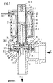
- the servo valve shown in FIGS. 1 and 2 has a valve housing 21 with an inlet Z and an outlet A.
- a differential piston 22 is movably arranged, which carries a valve plate 23 which is integrated into a rolling diaphragm 27, the outer edge of which 27.1 is connected to the valve housing 21, while its inner edge 27.2 is connected to the valve plate 23.
- the rolling diaphragm 27 separates the pressure chamber 25, which is connected to the valve inlet Z, from the control chamber 26, which is connected to the valve outlet A via the relief bore 22.1 and to the pressure chamber 25 via the control bore 22.2.
- the pressure chamber 25 is connected to the outlet A via the valve seat 24 when the valve is open.
- control chamber 26 contains a spring element 38 which has a straight section 38.1 which is guided through the control bore 22.2.
- a magnet system for controlling the valve is arranged with a magnet coil 31, which has electrical connections 31.1 and in which a guide tube 30 is arranged, the extended end 30.1 of the control chamber 26 above and on the sides limited.
- the guide tube 30 On its upper side, the guide tube 30 has a fixed end wall 30.2.
- Both the magnet armature 28 and the head piece 32 are arranged axially displaceably in the guide tube 30.
- the head piece 32 has on the side facing away from the magnet armature 28 an axial bore 32.1, in which a helical spring 34 acting as a return spring is arranged, which is supported with its outer end on the end wall 30.2.
- the head piece 32 On the side facing the magnet armature 28, the head piece 32 is supported on the magnet armature seal 28.1 by means of a rod-shaped spacer 35 which is guided through a longitudinal central bore 28.2 of the magnet armature 28. 2 and 4, the magnet armature seal 28.1 is integrated in an elastic membrane 29.2, which is arranged in the interior of a tubular holding element 29.
- the holding element 29 is fastened to the armature 28 by its end, while the other end 29.1 is opposite a support collar 36, which is arranged coaxially to the relief bore 22.1 on the surface of the differential piston 22.
- the support collar 36 as can be seen in FIG.
- the holding element 29 with the membrane 29.2 and the magnet armature seal 28.1 consists of a material, that has the best possible recovery properties, for example made of a silicone material.
- the arrangement of the membrane 29.2 within the holding element 29 is selected at such a distance from the lower end 29.1 and the elasticity of the membrane 29.2 is set such that when the armature 28 is in contact with the head piece 32, the magnet armature seal 28.1 on the underside of the holding element 29 is pressed out and on can open the opening of the relief bore 22.1.
- the length of the spacer 35 is dimensioned such that in the de-energized state of the magnet coil 31, the distance between the mutually facing surfaces of the magnet armature 28 and the head piece 32 corresponds at least to the path of the magnet armature seal 28.1 necessary for closing the relief bore 22.1.
- a short-circuit ring 37 can be arranged in the surface of the head piece 32 facing the magnet armature 28.
- the magnet coil 31 is surrounded by a magnet yoke 33.
- the head piece 32 and the magnet armature 28 are held at a predetermined distance by the action of the elastic membrane 29.2 via the spacer 35.
- the lower edge 29.1 of the mounting element 29 is seated on the support collar 36 and when the membrane 29.2 is relaxed and the magnet armature seal 28.1 is raised accordingly, the relief bore 22.1 is open and thus the valve under the action of the medium pressure in the open position.
- Appropriate training and prestressing of the roller membrane 27 can ensure this that the servo valve is open even at medium pressure 0.
Landscapes
- Engineering & Computer Science (AREA)
- General Engineering & Computer Science (AREA)
- Mechanical Engineering (AREA)
- Magnetically Actuated Valves (AREA)
- Valve Device For Special Equipments (AREA)
- Servomotors (AREA)
Description
- Die Erfindung betrifft ein eigenmediumbetätigtes, durch einen Magnetanker gesteuertes Servoventil mit den Merkmalen aus dem Oberbegriff des Patentanspruchs 1.
- Derartige Servoventile sind an sich bekannt und beispielsweise in der FR-A- 1 517 425 und FR-A- 1 280 661 beschrieben.
- Bei diesen bekannten Servoventilen sind die Distanzhalter an den Seiten des Magnetankers entlanggeführt und stutzen sich direkt auf dem Differentialkolben ab. Aufgrund ihrer Konstruktion öffnen die Ventile bei Erregung der Magnetspule.
- Es sind auch Servoventile bekannt, bei denen das den Magnetanker aufweisende Magnetsystem räumlich getrennt vom Steuerraum des Ventils am Ventilgehäuse angeordnet ist, wobei die vom Magnetanker zu verschließende Entlastungsbohrung dem Auslaß des Ventils zugeordnet ist. Ein derartiges Ventil ist beispielsweise in der DE-A-38 22 830 beschrieben. Bei derartigen Ventilen muß der Magnetanker nur den Hub ausführen, der zur Öffnung der Entlastungsbohrung erforderlich ist. Dadurch halten sich die Anforderungen an die notwendige elektrische Leistung für das Magnetsystem in Grenzen, die Ventile lassen sich aber sehr viel weniger einfach und kompakt aufbauen.
- Der Erfindung liegt die Aufgabe zugrunde, ein Servoventil mit den Merkmalen aus dem Oberbegriff des Patentanspruchs 1 zu schaffen, das bei allen Vorteilen, welche die Bauart mit koaxial zum Differentialkolben angeordnetem Magnetanker bietet, so ausgebildet ist, daß es im erregten Zustand der Magnetspule schließt.
- Die Lösung dieser Aufgabe erfolgt erfindungsgemäß mit den Merkmalen aus dem kennzeichnenden Teil des Patentanspruchs 1. Vorteilhafte Ausführungsformen des erfindungsgemäßen Servoventils sind in den Unteransprüchen beschrieben.
- Der Grundgedanke der Erfindung besteht darin, ein Ventil, das im erregten Zustand der Magnetspule schließt, in der Weise zu verwirklichen, daß das Kopfstück sich über einen Distanzhalter nicht auf dem Differentialkolben, sondern auf der in besonderer Weise ausgestalteten Magnetankerdichtung abstützt, die beispielsweise über eine elastische Membran mit der dem Differentialkolben zugewandten Seite des Magnetankers verbunden ist. Beim Schließen dieses Ventils werden Magnetanker und Kopfstück aufeinander zu bewegt und dadurch über den Distanzhalter die Magnetankerdichtung auf die Entlastungsbohrung gedrückt. Beim Öffnen des Ventils hebt sich unter der Einwirkung der elastischen Membran die Magnetankerdichtung von der Entlastungsbohrung ab und verschiebt über den Distanzhalter das Kopfstück.
- Durch Anordnung einer Rückstellfeder zwischen dem Kopfstück und einen mit dem Gehäuse fest verbundenen Anschlag kann dafür gesorgt werden, daß die Funktion beider prinzipieller Ausführungsformen des Servoventils lageunabhängig ist.
- Im Folgenden wird anhand der beigefügten Zeichnungen ein Ausführungsbeispiel für ein Servoventil nach der Erfindung näher erläutert.
- In den Zeichnungen zeigen:
- Fig. 1
- einen Längsschnitt durch ein bei erregter Magnetspule schließendes Servoventil im geöffneten Zustand;
- Fig. 2
- einen Längsschnitt durch das Servoventil analog Fig. 1 im geschlossenen Zustand;
- Fig. 3
- eine Aufsicht auf den Differentialkolben des Servoventils nach Fig. 1 und 2;
- Fig. 4
- einen vergrößerten Teilschnitt durch den Bereich der Magnetankerdichtung bei dem Servoventil nach Fig. 1 bis 3.
- Das in den Fig. 1 und 2 dargestellte Servoventil besitzt ein Ventilgehäuse 21 mit einem Einlaß Z und einem Auslaß A. Im Ventilgehäuse 21 ist ein Differentialkolben 22 bewegbar angeordnet, der einen Ventilteller 23 trägt, der in eine Rollmembran 27 integriert ist, deren äußerer Rand 27.1 mit dem Ventilgehäuse 21 verbunden ist, während ihr innerer Rand 27.2 mit dem Ventilteller 23 verbunden ist. Die Rollmembran 27 trennt den Druckraum 25, der mit dem Ventileinlaß Z verbunden ist, von dem Steuerraum 26, der über die Entlastungsbohrung 22.1 mit dem Ventilauslaß A und über die Steuerbohrung 22.2 mit dem Druckraum 25 verbunden ist. Der Druckraum 25 ist über den Ventilsitz 24 bei geöffnetem Ventil mit dem Auslaß A verbunden.
- Bei dieser Ausführungsform enthält der Steuerraum 26 ein Federelement 38, das einen durch die Steuerbohrung 22.2 hindurchgeführten geraden Abschnitt 38.1 aufweist.
- An der in Fig. 1 und 2 oberen Seite des Ventilgehäuses 21 ist ein Magnetsystem zur Steuerung des Ventils angeordnet mit einer Magnetspule 31, welche elektrische Anschlüsse 31.1 aufweist und in der ein Führungsrohr 30 angeordnet ist, dessen erweitertes Ende 30.1 den Steuerraum 26 oben und an den Seiten begrenzt. An seiner Oberseite besitzt das Führungsrohr 30 ein feste Abschlußwand 30.2. Im Führungsrohr 30 sind sowohl der Magnetanker 28 als auch das Kopfstück 32 axial verschiebbar angeordnet. Das Kopfstück 32 besitzt an der vom Magnetanker 28 abgewandten Seite eine axiale Bohrung 32.1, in der eine als Rückstellfeder wirkende Schraubenfeder 34 angeordnet ist, die sich mit ihrem äußeren Ende an der Abschlußwand 30.2 abstützt. An der dem Magnetanker 28 zugewandten Seite stützt sich das Kopfstück 32 über einen stabförmigen Distanzhalter 35, der durch eine Längsmittelbohrung 28.2 des Magnetankers 28 geführt ist, auf der Magnetankerdichtung 28.1 ab. Wie den Fig. 2 und 4 zu entnehmen, ist die Magnetankerdichtung 28.1 in eine elastische Membran 29.2 integriert, die im Inneren eines rohrförmigen Halteelements 29 angeordnet ist. Das Halteelement 29 ist mit seinem dem Magnetanker 28 zugewandten Ende an diesem befestigt, während das andere Ende 29.1 einem Abstützkragen 36 gegenüberliegt, der koaxial zur Entlastungsbohrung 22.1 auf der Oberfläche des Differentialkolbens 22 angeordnet ist. Der Abstützkragen 36 besitzt, wie aus Fig. 3 zu entnehmen, vier radiale Öffnungen 36.1, damit das Medium aus- und eintreten kann und in der Mitte des Abstützkragens 36 ist die Öffnung der Entlastungsbohrung 22.1 an der Spitze eines kegelförmigen Ansatzes 22.3 angeordnet. Die Höhe des Ansatzes 22.3 entspricht im wesentlichen der Höhe des Abstützkragens 36. Das Halteelement 29 mit der Membran 29.2 und der Magnetankerdichtung 28.1 besteht aus einem Material, das möglichst gute Rückstelleigenschaften besitzt, beispielsweise aus einem Siliconwerkstoff. Die Anordnung der Membran 29.2 innerhalb des Halteelements 29 ist in einem solchen Abstand vom unteren Ende 29.1 gewählt und die Elastizität der Membran 29.2 derart festgelegt, daß bei am Kopfstück 32 anliegenden Magnetanker 28 die Magnetankerdichtung 28.1 an der Unterseite des Halteelements 29 herausgedrückt wird und sich auf die Öffnung der Entlastungsbohrung 22.1 aufsetzen kann. Die Länge des Distanzhalters 35 ist so bemessen, daß im entregten Zustand der Magnetspule 31 der Abstand zwischen den einander zugewandten Oberflächen des Magnetankers 28 und des Kopfstücks 32 mindestens den zum Schließen der Entlastungsbohrung 22.1 notwendigen Weg der Magnetankerdichtung 28.1 entspricht.
- In der dem Magnetanker 28 zugewandten Fläche des Kopfstücks 32 kann ein Kurzschlußring 37 angeordnet sein. Die Magnetspule 31 ist von Magnetjoch 33 umfaßt.
- Die Funktionsweise des in den Fig. 1 bis 4 dargestellten Servoventils ist folgende:
- In dem in Fig. 1 dargestellten entregten Zustand der Magnetspule 31 werden Kopfstück 32 und Magnetanker 28 durch die Wirkung der elastischen Membran 29.2 über den Distanzhalter 35 in einem vorgegebenen Abstand gehalten. Der untere Rand 29.1 des Halterungselementes 29 sitzt auf dem Abstützkragen 36 auf und bei entspannter Membran 29.2 und entsprechend angehobener Magnetankerdichtung 28.1 ist die Entlastungsbohrung 22.1 geöffnet und damit das Ventil unter der Einwirkung des Mediumsdruckes in der Offenstellung. Durch entsprechende Ausbildung und Vorspannung der Rollmembran 27 kann dafür gesorgt werden, daß das Servoventil auch bei Mediumsdruck 0 geöffnet ist. Dies kann beispielsweise, wie in der älteren nicht vorveröffentlichten DE-OS 39 29 551 beschrieben, dadurch geschehen, indem die Rollmembran 27 durch Vulkanisation in der der Öffnungsstellung des Ventiltellers entsprechenden Stellung erzeugt wird, so daß sie sich in ihrer entspannten Ruhestellung in einer Lage befindet, die der Öffnung des Ventils entspricht.
- Bei Erregung der Magnetspule 31 werden die Rolflächen des Magnetankers 28 und des Kopfstücks 32 zusammengezogen, was zur Folge hat, daß der Distanzhalter 35 die Magnetankerdichtung 28.1 nach unten schiebt, wobei sich die Membran 29.2 nach unten wölbt und vorspannt. Dadurch wird die Magnetankerdichtung auf die Öffnung der Entlastungsbohrung 22.1 aufgedrückt und diese wird abgedichtet. Der untere Rand des Halterungselenentes 29 hebt vom Abstützkragen 36 ab und der Differentialkolben 22 senkt sich unter dem Einfluß des Mediumsdrucks, so daß der Ventilteller 23 auf dem Ventilsitz 24 aufsitzt. Das Servoventil befindet sich im geschlossenen Zustand.
- Bei dieser Ausführung des Ventils sind mit minimalen magnetischen Kräften große Ventilhübe überwindbar und die Steuerleistung liegt im Milliwattbereich.
Claims (9)
- Eigenmediumbetätigtes, durch einen Magnetanker gesteuertes Servoventil mit einem in einem Ventilgehäuse (21) bewegbar angeordneten, den Ventilteller (23) tragenden Differentialkolben (22) an dessen einer Seite ein mit dem Ventileinlaß (Z) verbundener Druckraum (25) angeordnet ist, der über einen dem Ventilteller (23) gegenüberliegenden Ventilsitz (24) mit dem Ventilauslaß (A) verbunden ist und an dessen anderer Seite ein Steuerraum (26) angeordnet ist, der über eine mittig im Differentialkolben (22) angeordnete Entlastungsbohrung (22.1) mit dem Ventilauslaß (A) und über eine außermittig im Differentialkolben angeordnete Steuerbohrung (22.2) mit dem Druckraum (25) verbunden ist und bei dem der koaxial zum Differentialkolben (22) angeordnete, in einer Magnetspule (11, 31) geführte Magnetanker (28) an seinem in den Steuerraum (26) hineingeführten einen Ende eine der Entlastungsbohrung gegenüberliegende Magnetankerdichtung (28.1) aufweist, während sein anderes Ende einem koaxial zum Magnetanker und mindestens teilweise in der Magnetspule angeordneten Kopfstück (32) gegenüberliegt, wobei das Kopfstück (32) in axialer Richtung verschiebbar angeordnet ist und sich an seiner, dem Magnetanker (28) zugewandten Seite auf einem Distanzhalter (35) abstützt, der relativ zum Magnetanker verschiebbar derart geführt ist, daß sich sein vom Kopfstück (32) abgewandtes Ende auf einem bewegbaren Bauteil (28.1) des Ventils derart abstützt, daß im entregten Zustand der Magnetspule sich aufgrund einer zwischen Magnetanker (28) und Kopfstück (32) wirksamen Federkraft (29.2) ein vorgegebener Abstand zwischen Magnetanker (28) und Kopfstück (32) einstellt, während im erregten Zustand der Magnetspule (31) Magnetanker (28) und Kopfstück (32) gegen die Wirkung dieser Federkraft aneinander anliegen, dadurch gekennzeichnet, daß für ein im erregten Zustand der Magnetspule (31) schließendes Servoventil der Distanzhalter (35) durch eine Längsmittelbohrung (28.2) des Magnetankers (28) hindurchgeführt ist und sich auf der von der Entlastungsbohrung (22.1) abgewandten Seite der Magnetankerdichtung (28.1) abstützt, die als bewegbares Bauteil über ein federndes Element (29.2) mit dem Magnetanker (28) verbunden ist derart, daß sie bei erregter Magnetspule (31) gegen die Kraftwirkung des federnden Elementes (29.2) aufgrund der Relativbewegung zwischen Magnetanker (28) und Kopfstück (32) vom Distanzhalter (35) auf die Entlastungsbohrung (22.1) aufgedrückt wird, wobei die Länge des Distanzhalters (35) so bemessen ist, daß im entregten Zustand der Magnetspule (31) der Abstand zwischen den einander zugewandten Flächen des Magnetankers (28) und des Kopfstücks (32) mindestens dem zum Schließen der Entlastungsbohrung notwendigen Weg der Magnetankerdichtung (28.1) entspricht.
- Servoventil nach Anspruch 1, dadurch gekennzeichnet, daß das federnde Element eine Membran (29.2) ist, in welche die Magnetankerdichtung (28.1) integriert ist und deren äußerer Rand mit dem Außenrand der dem Differentialkolben (22) zugewandten Fläche des Magnetankers (28) verbunden ist.
- Servoventil nach Anspruch 2, dadurch gekennzeichnet, daß die Membran (29.2) innerhalb eines koaxial zum Magnetanker (28) angeordneten rohrförmigen Halteelements (29) angeordnet ist, dessen eines Ende mit dem Magnetanker (28) verbunden ist, während das andere Ende dem Differentialkolben (22) gegenüberliegt, wobei der Abstand zwischen der Membran (29.2) und diesem Ende derart ist, daß im entregten Zustand der Magnetspule (31) sich der Magnetanker (28) über das Halteelement (29) auf dem Differentialkolben (22) abstützt, wobei ein vorgegebener Abstand zwischen Magnetankerdichtung (28.1) und Entlastungsbohrung (22.1) sichergestellt ist.
- Servoventil nach Anspruch 3, dadurch gekennzeichnet, daß der Differentialkolben (22) in einem dem Ende des Halteelements (29) gegenüberliegenden Bereich einen ringförmigen Abstützkragen (36) aufweist, der mindestens eine radiale Öffnung (36.1) besitzt und in dessen Mitte die Öffnung der Entlastungsbohrung (22.1) an der Spitze eines kegelförmigen Ansatzes (22.3) angeordnet ist, wobei die Höhe des Abstützkragens (36) im wesentlichen der Höhe des kegelförmigen Ansatzes (22.3) entspricht.
- Servoventil nach Anspruch 3 oder 4, dadurch gekennzeichnet, daß Halterungselement (29), Membran (29.2) und Magnetankerdichtung (28.1) einstückig aus Siliconmaterial bestehen.
- Servoventil nach einem der Ansprüche 1 bis 5, dadurch gekennzeichnet, daß das Kopfstück (32) sich an der vom Magnetanker (28) abgewandten Seite über eine Rückstellfeder (34) an eine mit dem Gehäuse fest verbundenen Anschlag (30.2) abstützt.
- Servoventil nach einem der Ansprüche 1 bis 6, dadurch gekennzeichnet, daß Magnetanker (8, 28) und Kopfstück (32) in einem fest mit dem Gehäuse (21) verbundenen, die Magnetspule (31) durchsetzenden dünnwandigen Führungsrohr (36) geführt sind.
- Servoventil nach Anspruch 7, dadurch gekennzeichnet, daß das Führungsrohr an seiner dem Differentialkolben (22) zugewandten Seite eine den Steuerraum (26) teilweise umfassende Verbreiterung (20.1) aufweist.
- Servoventil nach einem der Ansprüche 1 bis 8, dadurch gekennzeichnet, daß in der dem Magnetanker (28) gegenüberliegenden Fläche des Kopfstücks (22) ein Kurzschlußring (37) angeordnet ist.
Applications Claiming Priority (2)
| Application Number | Priority Date | Filing Date | Title |
|---|---|---|---|
| DE4038736 | 1990-12-05 | ||
| DE4038736A DE4038736A1 (de) | 1990-12-05 | 1990-12-05 | Eigenmediumbetaetigtes, durch einen magnetanker gesteuertes servoventil |
Publications (2)
| Publication Number | Publication Date |
|---|---|
| EP0489331A1 EP0489331A1 (de) | 1992-06-10 |
| EP0489331B1 true EP0489331B1 (de) | 1995-05-10 |
Family
ID=6419615
Family Applications (1)
| Application Number | Title | Priority Date | Filing Date |
|---|---|---|---|
| EP91120095A Expired - Lifetime EP0489331B1 (de) | 1990-12-05 | 1991-11-26 | Eigenmediumbetätigtes, durch einen Magnetanker gesteuertes Servoventil |
Country Status (4)
| Country | Link |
|---|---|
| EP (1) | EP0489331B1 (de) |
| AT (1) | ATE122444T1 (de) |
| DE (2) | DE4038736A1 (de) |
| DK (1) | DK0489331T3 (de) |
Cited By (3)
| Publication number | Priority date | Publication date | Assignee | Title |
|---|---|---|---|---|
| DE202006001009U1 (de) * | 2006-01-24 | 2007-06-06 | A. u. K. Müller GmbH & Co KG | Eigenmediumbetätigtes durch einen Magnetanker gesteuertes Servoventil |
| DE102009045773A1 (de) * | 2009-10-16 | 2011-04-21 | Prominent Dosiertechnik Gmbh | Druckhalteventil |
| EP4663989A1 (de) * | 2024-06-13 | 2025-12-17 | Neoperl GmbH | Sanitärventil mit pilotventil |
Families Citing this family (6)
| Publication number | Priority date | Publication date | Assignee | Title |
|---|---|---|---|---|
| DE4438065A1 (de) * | 1994-10-25 | 1996-05-02 | Rexroth Mannesmann Gmbh | Vorgesteuertes 2/2-Wege-Sitzventil |
| EP1416207A1 (de) * | 2002-10-30 | 2004-05-06 | Rpe S.R.L. | Membrangesteuertes Ventil mit einem elektromagnetischen Vorsteuerventil |
| ITMI20130403U1 (it) | 2013-11-19 | 2015-05-20 | Rpe Srl | Valvola, in particolare valvola di scarico di acqua per servizi igienici |
| US11788644B2 (en) | 2014-12-03 | 2023-10-17 | Hydralectric Group Ltd | Proportional valve, electric shower incorporating the proportional valve and tap incorporating same |
| EP4112984A1 (de) | 2021-06-30 | 2023-01-04 | Danfoss A/S | Vorgesteuertes magnetventil |
| CN114542328B (zh) * | 2022-03-03 | 2024-01-09 | 北京星河动力航天科技股份有限公司 | 组合阀、火箭发动机及运载火箭 |
Family Cites Families (3)
| Publication number | Priority date | Publication date | Assignee | Title |
|---|---|---|---|---|
| FR1280661A (fr) * | 1960-11-18 | 1962-01-08 | Neypric Ets | Clapet à commande électro-magnétique |
| BE694157A (de) * | 1966-05-14 | 1967-07-31 | ||
| DE2439271A1 (de) * | 1974-08-16 | 1976-03-11 | Herion Werke Kg | Durchgangsmagnetventil |
-
1990
- 1990-12-05 DE DE4038736A patent/DE4038736A1/de not_active Withdrawn
-
1991
- 1991-11-26 EP EP91120095A patent/EP0489331B1/de not_active Expired - Lifetime
- 1991-11-26 DK DK91120095.4T patent/DK0489331T3/da active
- 1991-11-26 DE DE59105441T patent/DE59105441D1/de not_active Expired - Fee Related
- 1991-11-26 AT AT91120095T patent/ATE122444T1/de not_active IP Right Cessation
Cited By (3)
| Publication number | Priority date | Publication date | Assignee | Title |
|---|---|---|---|---|
| DE202006001009U1 (de) * | 2006-01-24 | 2007-06-06 | A. u. K. Müller GmbH & Co KG | Eigenmediumbetätigtes durch einen Magnetanker gesteuertes Servoventil |
| DE102009045773A1 (de) * | 2009-10-16 | 2011-04-21 | Prominent Dosiertechnik Gmbh | Druckhalteventil |
| EP4663989A1 (de) * | 2024-06-13 | 2025-12-17 | Neoperl GmbH | Sanitärventil mit pilotventil |
Also Published As
| Publication number | Publication date |
|---|---|
| DE59105441D1 (de) | 1995-06-14 |
| DE4038736A1 (de) | 1992-06-11 |
| DK0489331T3 (da) | 1995-09-04 |
| ATE122444T1 (de) | 1995-05-15 |
| EP0489331A1 (de) | 1992-06-10 |
Similar Documents
| Publication | Publication Date | Title |
|---|---|---|
| EP0578168B1 (de) | Ventil | |
| DE19826076C1 (de) | Doppelsicherheitsventil | |
| EP3263962B1 (de) | Ventil | |
| DE4439890C2 (de) | Ventilanordnung | |
| DE3410795C2 (de) | elektropneumatischer Wandler | |
| DE3823430C3 (de) | Hydraulischer Teleskopstoßdämpfer | |
| DE4208886A1 (de) | Daempfkraftveraenderbarer schwingungsdaempfer mit notbetriebseinstellung | |
| EP1004066A1 (de) | Elektromagnetisches druckregelventil | |
| DE2757803A1 (de) | Magnetventil | |
| EP3039324B1 (de) | Ventilanordnung | |
| DE10040763A1 (de) | Elektromagnetisch betätigtes Ventil, insbesondere für hydraulische Bremsanlagen in Kraftfahrzeugen | |
| WO1999064769A2 (de) | Doppelsicherheitsventil | |
| EP0489331B1 (de) | Eigenmediumbetätigtes, durch einen Magnetanker gesteuertes Servoventil | |
| WO2005066531A1 (de) | Elektromagnetisches ventil, insbesondere für eine bremsanlage eines kraftfahrzeugs | |
| EP0416339A1 (de) | Eigenmediumbetätigtes durch einen Magnetanker gesteuertes Servoventil | |
| DE3439378C2 (de) | ||
| DE3780642T2 (de) | Elektromagnetisches ventil. | |
| DE2855902A1 (de) | Elektromagnetisch betaetigbares 3/2-wegeventil, insbesondere zur fernsteuerung von einseitig mit einem fluid beaufschlagbaren vorrichtungen | |
| DE4201450C1 (de) | ||
| DE2657197A1 (de) | Elektromagnetische ventileinrichtung | |
| DE10216485B4 (de) | Verfahren zur Einstellung eines Elektromagnetventils | |
| DE3705514C2 (de) | ||
| EP3844374A1 (de) | Ventil | |
| WO1998033687A1 (de) | Mehrwege-regelventil | |
| EP3643954A1 (de) | Elektromagnetisches ventil, verfahren zum betrieb eines elektromagnetischen ventils |
Legal Events
| Date | Code | Title | Description |
|---|---|---|---|
| PUAI | Public reference made under article 153(3) epc to a published international application that has entered the european phase |
Free format text: ORIGINAL CODE: 0009012 |
|
| AK | Designated contracting states |
Kind code of ref document: A1 Designated state(s): AT BE CH DE DK FR GB IT LI NL |
|
| 17P | Request for examination filed |
Effective date: 19921125 |
|
| 17Q | First examination report despatched |
Effective date: 19940225 |
|
| GRAA | (expected) grant |
Free format text: ORIGINAL CODE: 0009210 |
|
| ITF | It: translation for a ep patent filed | ||
| AK | Designated contracting states |
Kind code of ref document: B1 Designated state(s): AT BE CH DE DK FR GB IT LI NL |
|
| PG25 | Lapsed in a contracting state [announced via postgrant information from national office to epo] |
Ref country code: GB Effective date: 19950510 Ref country code: BE Effective date: 19950510 |
|
| REF | Corresponds to: |
Ref document number: 122444 Country of ref document: AT Date of ref document: 19950515 Kind code of ref document: T |
|
| REF | Corresponds to: |
Ref document number: 59105441 Country of ref document: DE Date of ref document: 19950614 |
|
| ET | Fr: translation filed | ||
| REG | Reference to a national code |
Ref country code: DK Ref legal event code: T3 |
|
| GBV | Gb: ep patent (uk) treated as always having been void in accordance with gb section 77(7)/1977 [no translation filed] |
Effective date: 19950510 |
|
| PG25 | Lapsed in a contracting state [announced via postgrant information from national office to epo] |
Ref country code: AT Effective date: 19951126 |
|
| PG25 | Lapsed in a contracting state [announced via postgrant information from national office to epo] |
Ref country code: LI Effective date: 19951130 Ref country code: CH Effective date: 19951130 |
|
| PLBE | No opposition filed within time limit |
Free format text: ORIGINAL CODE: 0009261 |
|
| STAA | Information on the status of an ep patent application or granted ep patent |
Free format text: STATUS: NO OPPOSITION FILED WITHIN TIME LIMIT |
|
| 26N | No opposition filed | ||
| PG25 | Lapsed in a contracting state [announced via postgrant information from national office to epo] |
Ref country code: NL Effective date: 19960601 |
|
| REG | Reference to a national code |
Ref country code: CH Ref legal event code: PL |
|
| NLV4 | Nl: lapsed or anulled due to non-payment of the annual fee |
Effective date: 19960601 |
|
| PGFP | Annual fee paid to national office [announced via postgrant information from national office to epo] |
Ref country code: FR Payment date: 19991029 Year of fee payment: 9 |
|
| PGFP | Annual fee paid to national office [announced via postgrant information from national office to epo] |
Ref country code: DK Payment date: 19991126 Year of fee payment: 9 |
|
| PGFP | Annual fee paid to national office [announced via postgrant information from national office to epo] |
Ref country code: DE Payment date: 19991210 Year of fee payment: 9 |
|
| PG25 | Lapsed in a contracting state [announced via postgrant information from national office to epo] |
Ref country code: DK Free format text: LAPSE BECAUSE OF NON-PAYMENT OF DUE FEES Effective date: 20001126 |
|
| REG | Reference to a national code |
Ref country code: DK Ref legal event code: EBP |
|
| PG25 | Lapsed in a contracting state [announced via postgrant information from national office to epo] |
Ref country code: FR Free format text: LAPSE BECAUSE OF NON-PAYMENT OF DUE FEES Effective date: 20010731 |
|
| PG25 | Lapsed in a contracting state [announced via postgrant information from national office to epo] |
Ref country code: DE Free format text: LAPSE BECAUSE OF NON-PAYMENT OF DUE FEES Effective date: 20010801 |
|
| REG | Reference to a national code |
Ref country code: FR Ref legal event code: ST |
|
| PG25 | Lapsed in a contracting state [announced via postgrant information from national office to epo] |
Ref country code: IT Free format text: LAPSE BECAUSE OF NON-PAYMENT OF DUE FEES;WARNING: LAPSES OF ITALIAN PATENTS WITH EFFECTIVE DATE BEFORE 2007 MAY HAVE OCCURRED AT ANY TIME BEFORE 2007. THE CORRECT EFFECTIVE DATE MAY BE DIFFERENT FROM THE ONE RECORDED. Effective date: 20051126 |