EP0488563A2 - Verfahren und Gerät zur Wiedergabe von abgeglichenen parametrischen Oberflächen - Google Patents
Verfahren und Gerät zur Wiedergabe von abgeglichenen parametrischen Oberflächen Download PDFInfo
- Publication number
- EP0488563A2 EP0488563A2 EP91310634A EP91310634A EP0488563A2 EP 0488563 A2 EP0488563 A2 EP 0488563A2 EP 91310634 A EP91310634 A EP 91310634A EP 91310634 A EP91310634 A EP 91310634A EP 0488563 A2 EP0488563 A2 EP 0488563A2
- Authority
- EP
- European Patent Office
- Prior art keywords
- polyline
- polygon
- trim
- data
- vertex
- Prior art date
- Legal status (The legal status is an assumption and is not a legal conclusion. Google has not performed a legal analysis and makes no representation as to the accuracy of the status listed.)
- Withdrawn
Links
Images


Classifications
-
- G—PHYSICS
- G06—COMPUTING OR CALCULATING; COUNTING
- G06T—IMAGE DATA PROCESSING OR GENERATION, IN GENERAL
- G06T15/00—Three-dimensional [3D] image rendering
- G06T15/50—Lighting effects
Definitions
- This invention relates to a method and apparatus for rendering trimmed parametric surfaces, especially trimmed NURBS surfaces, in a computer graphics display system.
- Graphics entities also known as primitive elements, or primitives consist of lines, curves, polygons, curved surfaces, and other two-dimensional (2D) and three-dimensional (3D) entities. These entities are usually stored in a form which efficiently encodes the basic parameters (endpoints of a line, centre and radius of a circle, etc.), but is not directly representable on a raster-scan display, in which successive pixels, or pels, are illuminated as appropriate for the entity being represented.
- To "render" a graphics entity is to convert the entity from its high-level form ultimately to pixel data, which is stored in a frame buffer having a location for each pixel being displayed.
- NURBS Non-Uniform Rational B-Spline
- U,V 2D parametric coordinate space
- X,Y,Z 3D geometric coordinate space
- NURBS representations would be used for surfaces (such as the wings or fuselage on an aircraft) that cannot be resolved into spherical, cylindrical or planar surfaces.
- the UV parameter space is divided, or tessellated, into contiguous U and V strips, or intervals, with the intervals intersecting to form a 2D array of UV rectangles.
- the NURBS surface is evaluated at the vertices of the UV rectangles by determining, for each vertex, the X, Y and Z geometric coordinates as well as the X, Y and Z components of a normal vector to the NURBS surface at that point.
- the vertex data for each UV rectangle is then set to a polygon processor, which processes the vertex data in a conventional manner to render the polygon.
- the polygon processor may generate edges of a defined colour, fill the interior of the polygon with a predefined colour, which may be different from the edge colour, or shade the interior of the polygon, using the normal vector data to determining shading.
- NURBS surfaces described in the above-identified application are untrimmed surfaces, i.e. surfaces whose extents are defined simply by minimum and maximum values of the parametric coordinates U and V. It would be desirable also to be able to render trimmed NURBS surfaces, i.e. surfaces whose extent in the UV parametric coordinate space is defined by a trimming curve in that space.
- a known method of rendering trimmed NURBS surfaces which may be used in conjunction with the method described in EP -A- 0425177, is to convert the trimming curve to a trim polyline (more particularly, a trim polygon enclosing a trimming region) approximating the trimming curve in parametric coordinate space.
- the trimming region bound by this trim polyline is made up of complete UV rectangles together with polygons of irregular shape formed by the intersection of the trimming region, bound by the trim polyline, with the UV rectangles along the periphery of the trimming region.
- the complete UV rectangles are rendered by the polygon processor in the usual manner.
- the irregular polygons on the other hand, are recursively subdivided into rectangles which, in the aggregate, approximate the original irregular polygon. These smaller rectangles, whose dimensions in XYZ geometric coordinate space approximate those of a pixel, are then sent to the polygon processor.
- the invention contemplates a method and apparatus for rendering a trimmed parametric surface, such as a NURBS surface, representing a mapping from U and V parametric coordinates to X, Y and Z geometric coordinates and having a trimming region bound by a trim polyline.
- the UV parametric surface is divided into contiguous U and V intervals intersecting to form UV rectangles, the trim polyline intersecting a subset of the UV rectangles to divide each of the rectangles of the subset into at least one polygon lying within the trimming region and at least one polygon lying outside the trimming region.
- the vertices of each polygon lying within the trimming region formed by the intersection of the trim polyline and the UV rectangle are determined, and vertex data for the vertices so determined is provided to a concave polygon processor to render the polygon.
- concave polygons in place of recursive subdivision greatly simplifies the processing of a surface in the regions close to the trimming curves. In most cases, this will lead to a significant increase in performance because it will not be necessary to subdivide the parameter space down to single pixels. In addition to eliminating the work required to generate many tiny polygons, it will relieve the graphics pipeline of the burden of processing all the extra vertices represented by these polygons. In some cases the processing of trimmed surfaces may be improved by a factor of three or more by this improvement. This use of concave polygons also provides accurate representations of the edges of trimmed surfaces, and makes it possible to support edge line styles for trimmed surfaces, because edges will be defined by vectors instead of many small polygons.
- the invention contemplates a method and apparatus for rendering a trimmed parametric surface such as a NURBS surface in a graphics system having a global memory in which trim polyline data is stored and a local memory associated with a graphics processor.
- the UV parametric surface is first divided into a plurality of contiguous V intervals. For each V interval intersected by the trim polyline, the polyline data stored in the global memory is read by the graphics processor, and the polyline defined by the read data clipped to form a V-clipped polyline defined by V-clipped data which is stored in local memory. The graphics processor then processes the V interval using the V-clipped polyline data stored in local memory.
- this change allows the process of clipping the trimming curves to a UV rectangle to be performed in two steps.
- the vertices are clipped to the V interval and the resulting clipped vertices, including any new vertices created where trim curves cross the V boundaries, are stored in local memory.
- the resulting vectors are clipped to the U interval. The XYZ coordinates and normal vectors of the resulting vertices are then sent to the graphics pipeline.
- NURBS Non-Uniform Rational B-Spline
- the X, Y and Z components of the normal vector N are determined in addition to the X, Y and Z coordinates of the point itself, because these components are used to control surface shading.
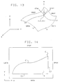
- a trimmed NURBS surface is one that is bound by a defined trimming contour in UV parameter space rather than by minimum and maximum U and V parameters as in Fig. 13.
- Fig. 14 shows an example of a trimmed NURBS surface S bounded by a trimming contour C comprising contiguous curves C1, C2 and C3.
- Trimmed NURBS surfaces may be represented using the Programmer's Hierarchical Interactive Graphics Standard (PHIGS) with extensions for lighting and shading (PHIGS+, PHIGS-BR, or PHIGS-PLUS).
- a trimming contour defines a trimming region.
- multiple trimming contours may be used, with the resultant trimming region being defined as the symmetric difference, or exclusive OR combination, of the constituent regions.
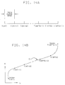
- two trimming contours C1 and C2 may have disjoint trimming regions R1 and R2 which form a resultant trimming region consisting of the two disjoint parts or, as shown in Fig. 14F, the trimming region of one contour C1 may encompass the region R2 of another contour C2, so that the resultant region R is doughnut shaped.
- Each of trimming curves C1 to C3 may be a NURBS curve, i.e. a particular mapping between values of the trim curve parameter T and points in UV parameter space.
- a trim curve C having a minimum parameter value TMIN and maximum parameter value TMAX is shown as it might exist in UV parameter space.
- the quantities U and V are referred to as parameters because they are ultimately mapped into XYZ coordinate space, they are here dependent variables, determined by the trim curve parameter T.
- a trim curve C of order KT in UV parameter space is defined by NPTS control points in UV space (not shown in the figures) and a knot vector of values t(i) in T parameter space of dimension NPTS + KT.
- the knot vector T(i) divides the trim curve into NPTS - KT + 1 spans, with knot value T(KT + i - 1) determining the value of the T parameter at the beginning of the ith span and knot value T(KT + i) defining the value of the T parameter at the end of the ith span.
- the curve is evaluated along a given span by determining from the knots and control points the U and V values corresponding to a point having a given T value along the span.
- the ith span of the curve is evaluated from KT control points i through KT + i - 1 and 2KT - 2 knot values T(i + 1) through T(2KT + i - 2), preferably using the Cox-DeBoor procedure described in EP -A-0425174.
- Points along the first span would be evaluated using control points 1 to KT and knot values T(2) to T(2KT - 1), while points along the last span would be evaluated using control points NPTS - KT + 1 to NPTS and knot values T(NPTS - KT + 3) to T(NPTS + KT - 1).
- knot values T(1) and T(NPTS + KT) are not used at all in the evaluation procedure. Further, knot values T(2) to T(KT - 1) and T(NPTS + 2) to T(NPTS + KT - 1) are not used to define trim curve spans, but are only used to evaluate the trim curves.
- the U order KU is mu + 1, where mu is the highest power of the U parameter in the parametric equations
- the V order KV is mv + 1, where mv is the highest power of the V parameter in the parametric equations.
- a NURBS surface of U order KU and V order KV is defined by a matrix of control points (Fig. 3A) in XYZ space having NU rows and NV columns, a U knot vector UKNOT(i) of dimension NU + KU, and a V knot vector VKNOT(j) of dimension NV + KV.
- the U knot vector UKNOT(i) divides the UV region into NU - KU + 1 U spans, with the knot value UKNOT(KV + i - 1) defining the beginning of the ith U span and the knot value UKNOT(KU + i) defining the end of the ith U span.
- the V knot vector VKNOT(j) divides the UV region into NV - KV + 1 V spans, with the knot value VKNOT(KV + j - 1) defining the beginning of the jth V span and the knot value VKNOT(KV + j) defining the end of the jth V span.
- a UV point is evaluated by determining the XYZ coordinates (and optionally the X, Y and Z components of the normal vector) corresponding to the point. Points in the ijth patch formed by the intersection of the ith U span and jth V span are evaluated from a subportion of the control point matrix (Fig.
- NURBS curves and surfaces are defined as continuous functions of the parameter values.
- a UV NURBS surface in XYZ space is a continuous mapping between UV parameter space and the XYZ target coordinate space
- a trimmed NURBS curve in UV parameter space is a continuous mapping between the trim curve parameter T and the UV target coordinate space.
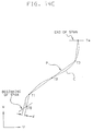
- a continuous trim curve portion C beginning at T0 and ending at T4 is tessellated into a polyline P comprising a plurality of piecewise linear contiguous intervals or segments T0-T1, T1-T2, T2-T3 and T3-T4 which approximate the ideal continuous curve C.
- a trim contour comprising one or more contiguous trim curves (each comprising one or more spans), may be approximated by a trim polygon.
- Multiple polygons (Fig. 14E) may be used to define topologically complex trimming regions, in the manner described above.
- a polygon processor receiving data for overlapping polygons combines the polygons in an exclusive OR fashion, as shown in Fig. 14F for smooth curves.
- a NURBS curve is tessellated into intervals on a span-by-span basis, with each span being divided into equal T intervals, the number of intervals being selected so as to keep the chordal deviation d (Fig. 14C) between the ideal curve C and the polyline P within predetermined bounds.
- each U and V span is divided -- or tessellated -- into a plurality of equal U or V intervals, the interval size being selected again as to keep the chordal deviation between the ideal surface and the approximated surface within bounds.
- a suitable tessellation procedure for NURBS surfaces is described in EP -A- 0425177.
- the trimming region R may be divided into polygons PG 1 to PG 13, each of which consists of that portion of a UV rectangle within the trimming region R.
- the trimming region consists of a single interior polygon PG 8 made up of an entire UV rectangle and peripheral polygons PG 1 to PG 7 and PG 9 to PG 13, each of which is made up of only a portion of a UV rectangle and may be concave (e.g. PG 5).
- the trimmed NURBS surface portion represented by trimming region R is rendered by determining, for each of the polygons PG 1 to PG 13 making up the trimming region R, the vertices of the polygon. (Except for the peripheral portions of the trimming region, these will typically be the corners of the UV rectangles.)
- vertex data for the polygon vertices is sent to a concave polygon processor to render the polygon. This data consists typically of the X, Y and Z coordinates of each vertex, together with the X, Y and Z components of the normal vector to the UV surface at the vertex.
- the X and Y values determine where the vertex is displayed on the screen
- the Z value provides depth information, which may be used for clipping or for determining which of two elements overlies the other and should be displayed, and the normal vector components may be used to determine shading.
- the vertex in question is also a vertex of the UV rectangle
- these values are evaluated using the Cox-DeBoor procedure referred to above or some comparable procedure.
- the vertex is along an edge or in the interior of a UV rectangle (e.g. P1 to P8 in Fig. 14D)
- the data for that vertex is calculated from the vertex data for the corners of the UV rectangle by either linear or bilinear interpolation, as described below.
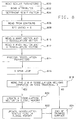
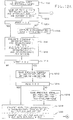
- Figure 1 The principal components of rendering apparatus used to practice this invention are ( Figure 1) (a) Global memory 102, (b) Graphics control processor (GCP) 104, (c) Drawing and shading processors 106, (d) Raster graphics display 108, (e) System bus 110, (f) Secondary bus 112.
- Global memory 102 consists of sufficient random access memory (RAM) to store the definitions of a number of graphics entities, as well as any additional information such as attributes (e.g. colours) and transformation matrices required to specify how and where these entities are to appear on a display screen. This information is produced by a general purpose host computer (not shown) using appropriate communications facilities (not shown).
- RAM random access memory
- Drawing and shading processors 106 contain the frame buffer(s) required to refresh the screen of raster graphics display 108.
- This component also includes logic for drawing straight lines between a pair of points on the screen and for filling polygonal areas bounded by straight lines between points on the screen.
- This component may optionally include a z-buffer to support hidden surface elimination, logic to interpolate the colours on the interior of a polygon between the colours of the vertices, and facilities to compute the colours at the vertices of a polygon based on standard lighting models.
- this component may contain a number of specialised microprocessors. The details of how these functions are provided are not part of this invention.
- Graphics control processor 104 is capable of selecting an individual graphics entity, as stored in global memory 102, and converting it into a form which is supported by drawing and shading processors 106. In the case of a trimmed NURBS surface, graphics control processor 104 generates a set of polygons with vertices specified in screen coordinates, based on the data for a trimmed NURBS surface. The details of this process are provided below.
- System bus 110 provides a high-speed data path between global memory 102, graphics control processor 104, and drawing and shading processors 106.
- the principal purpose of bus 110 in this invention is to provide for exchange of data between global memory 102 and the graphics control processor 104.
- Drawing and shading processors 106 may also be capable of communicating with global memory 102 and graphics control processor 104 through system bus 110, but this path is not used in the rendering of trimmed NURBS surfaces.
- Secondary bus 112 provides an alternate data path from the graphics control processor 104 to the drawing and shading processors 106. This allows graphics control processor 104 to send data to drawing and shading processors 106 without interfering with the communication between graphics control processor 104 and the global memory 102.
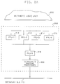
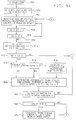
- the principal components of the graphics control processor 104 are ( Figure 2) (a) An arithmetic logic unit (ALU) 200, (b) Code memory 202 for the ALU, (c) Data memory 204 for the ALU, (d) A bus interface unit (BIU) 206, and (e) A graphics pipeline 208.
- ALU arithmetic logic unit
- BIU bus interface unit
- a graphics pipeline 208 A graphics pipeline 208.
- ALU 200 consists of an integer processing unit (IPU), a floating point processing unit (FPU), and a sequencer.
- the sequencer enables ALU 200 to process sequences of instructions stored in code memory 202, including branches, conditional branches and subroutine calls.
- the IPU performs the basic integer operations (add, subtract, multiply, shift, extract, merge, deposit) on integer values contained within a set of integer registers.
- the FPU performs the basic floating point operations (add, subtract, multiply, etc.) on floating point values stored within a set of floating point registers.
- Code memory 202 contains space for instructions within address space, and data memory (also called local memory) 204 provides random access storage.
- data memory also called local memory
- ALU 200 The operation of ALU 200 during the processing of a trimmed NURBS surface is described below.
- BIU 206 handles all communications protocols required to transfer data between ALU 200 and system bus 110. This unit 206 also buffers incoming data coming from the system bus 110 to ALU 200.
- Graphics pipeline 208 handles the transformation, culling, clipping, and mapping of vectors and polygons, as well as special functions to support the rendering of trimmed surfaces.
- the transformation, culling, clipping, and mapping functions are standard graphics functions and are not specific to this invention, and they will not be described here.
- the special functions in support of trimmed surfaces are described below.
- Graphics pipeline 208 (Fig. 2A) consists of a multiplicity of floating point processors (FPU) which transform vertex coordinates and normal vectors, clip vectors and polygons to a 3D rectangular window, map the clipped coordinates to device coordinates, and send the resulting data to the drawing and shading processors 106 via the secondary bus 110. More particularly, graphics pipeline 208 includes a set of four parallel floating point processors 210, 212, 214 and 216 (FPU1 to FPU4) which can receive commands and data from the ALU 200, and transmit commands and data to a fifth floating point processor 218 (FPU5). The fifth floating point processor 218 (FPU5) receives commands and data from the first four processors 210 to 216 and transmits commands and data to clipping and mapping processors 220.
- FPU5 floating point processors
- Floating point processors FPU1 to FPU4 perform the basic floating point operations (add, subtract, multiply, etc.) on floating point values stored within a set of floating point registers, and with PFU5 are used for the evaluation and interpolation steps described below.
- FPU1 to FPU4 may also be used to transform vertex coordinates and vertex normals of ordinary polygons (not necessarily associated with a trimmed surface), and FPU5 may be used to eliminate or change the colour of polygons based on the direction of the polygon normal vector.
- the polygon normal vector may be approximated with the sum of the vertex normal vectors. In this way, the same set of hardware may be used both to transform ordinary polygons and to generate polygons representing a trimmed surface.
- Clipping and mapping processors 220 receive commands and data from FPU5 and send commands and data to the drawing and shading processors 106 by way of the secondary bus 110.
- Processors 220 recognise the above polygon commands and data defining the vertices of a polygon. The data for the vertex coordinates is compared to a 3D volume determined by the boundaries of a rectangular window within the screen of a graphics display and the near and far limits for a coordinate (Z) perpendicular to the screen. If none of the vertex coordinates of a polygon falls within this volume, then the polygon is rejected, and no data or commands are sent to the drawing and shading processors 106.
- vertex normal vectors may also be normalised to unity in preparation for lighting and shading calculations to be performed by the drawing and shading processors.
- the functions of the clipping and mapping processors 220 may be provided by multiple microprocessors with appropriate connectivity. These functions are considered to be standard elementary graphics functions and they are not unique or specific to this invention. Consequently, the details of these functions will not be provided here.
- the graphics pipeline 208 provides the following functions to support of the rendering of trimmed surfaces:
- This command is followed by a sequence of vertex data records.
- the data for each vertex includes the coordinates and normal vector for the vertex. This sequence is terminated by the End Polygon command.
- This command is followed by a sequence of vertex data records.
- the data for each vertex includes the coordinates and normal vector for the vortex. This sequence is followed by the End Polygon command or the Break Polygon command.
- This command is followed by a sequence of vertex data records.
- the data for each vortex includes the coordinates and normal vector for the vortex.
- This sequence is followed by the End Polygon command or the Break Polygon command.
- This command may be used to separate successive subareas to be treated as a single polygon, and implies a connection between the preceding vortex and the first vortex following the most recent Start Concave Polygon or Break Polygon command.
- This command indicates the end of a polygon. It follows the last vertex, has no data, and implies a connection between the last vertex and the first vertex following the most recent Start Convex Polygon, Start Concave Polygon, or Break Polygon command.
- Additional commands to load transformation matrices, colours, clipping boundaries, and the like may be provided to prepare the graphics pipeline for the rendering of a trimmed surface. As these commands are not relevant to the present invention, they will not be described here.
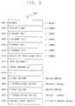
- the first section includes the following entries:
- the data specifying the trimming contours consists of one word (312) which indicates the total length (number of bytes) of the data for the trimming contours, followed by the data for one or more trimming contours (314-318).
- a trimming contour may also be referred to as a trimming loop.
- the data for each trimming contour or loop (e.g. 314) is summarised in Figure 4. This data consists of one word (400) indicating the number of bytes contained in the data representing the contour, followed by the data (402-406) for one or more trimming curves or segments.
- the knot vectors for each trimming curve consist of a non-decreasing sequence of parameter values.
- the data for the trimming contours in global memory 102 (Fig. 3) is followed by the four sets of vector data. These consist of the U knot vector (320) of NU + KU words, the tessellation vector (322) of NU - KU + 1 words, the V knot vector (324) of NV + KV words, and the V tessellation vector (326) of NV - kv + 1 words.
- the U and V knot vectors each consist of a non-decreasing sequence of parameter values.
- the fourth section of data consists of the control point matrix (328). This consists of NV data records, each composed of NU control points. Each control point consists of 3 or 4 words depending on the rational/non-rational bit in the status flags word.
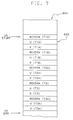
- the local memory 204 of the graphics control processor 104 is partitioned into eight sections ( Figure 6) consisting of:
- the first section (600) includes the transformation matrices, attributes, and other data required to control and support the processing of multiple windows, graphics structures, and structure elements. This processing may include, but is not limited to display list traversal. This processing is not specific to this invention and will not be described in this document.
- Section 2 (602-608) occupies one block and contains four vectors:
- the first element of the U knot vector is located NMAX - KU words beyond the beginning of the U tessellation vector.
- the first element of the V tessellation vector is located 2*NMAX words beyond the beginning of the U tessellation vector.
- the starting address of the V knot vector is located NMAX - KV words beyond the beginning of the V tessellation vector.
- Section 4 the V interval stack (612-614), also shown in Fig. 6A, contains four blocks of data.
- the first block contains NU sets of coordinates (Xi(V), Yi(V), Zi(V), Wi(V)) determined by the corresponding columns of the control point stack, the appropriate portion of the V knot vector, and the current value of the V parameter, while the second block contains the derivatives of the elements of the first block with respect to the V parameter (612).
- the third block contains the values located in the first block for the previous value of V, while the fourth block contains the values located in the second block for the previous value of V (614).
- Section 5 contains values characteristic of each patch within the row of patches determined by the contents of the control point stack.
- the first block in this section (616) contains the values of XMIN, YMIN, and ZMIN for each of the NU-KU+1 patches in this row, and a visibility flag (VIS) for each patch.
- the second block (618) contains XMAX, YMAX, and ZMAX for each patch, as well as the normal vector threshold (QMIN) for each visible patch.
- Section 6 contains the values of the following scalar quantities:
- Section 7 contains the data which specifies the locations of the trimming curves in the UV parameter space. Initially, this section contains the definitions of the trimming curves as NURBS curves. These curves are evaluated and the results (MOVDRW, U(T), V(T)) are stored in a work area in global memory 102. For each V interval, the trim curve data is copied from global memory 102 to graphics control processor 104 in a block transfer operation. The (U,V) coordinates in this data are clipped to the current V interval and the resulting clipped coordinates are stored in local memory 204, overwriting the NURBS representations in this section.
- each trimming curve consists of a header record and a sequence of control point records.
- the header record consists of 6 words and contains the values of the following quantities:
- the second word in the header includes the following bits:
- a record with NSTART 0 follows the last trimming contour (loop).
- control point records for each curve is given by NPNTS.
- Each control point record contains 15 words.
- the trim curves are represented by the disjoint UV polylines defined by a sequence of data records of the form (MOVDRW, U(T), V(T)).
- the values of U(T) and V(T) indicate a point on the surface in the UV parameter space.
- the MOVDRW values contain the following flags:
- the convexity of the resulting UV polygon may be tested using conventional means.
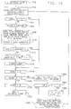
- the apparatus described above may be used to render a trimmed NURBS surface by means of the procedure outlined in Figure 8.
- This procedure has three principal stages: the initiation stage, the rendering stage, and the termination stage.
- the initiation stage consists of the following steps:
- the procedure enters the rendering stage (816) in which the trim surface is divided into a sequence of V spans and the portion of the surface contained within each V span is processed as shown in Figure 9, described below.
- the procedure enters the termination stage (818-824). If the U and V tessellation vectors were computed in this traversal (818), the V tessellation vector (820) and tessellation status flag (822) are updated in global memory 102 before terminating the procedure (824). If the U and V tessellation vectors were not computed in this traversal, the procedure terminates without updating any tessellation vectors or status flags.
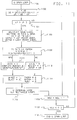
- the V span loop (900-948), constitutes the principal loop of the rendering stage.
- the V span loop begins by setting a variable IV, indicating the number of empty rows in the control point stack 610 in local memory 204, equal to the V order KV; setting a variable NSV, indicating the number of unprocessed V spans, equal to NV - KV, where NV is the V dimension of the control point matrix 328 in global memory 102; and setting V2, which indicates the upper limit of the span being processed, equal to VKNOT (KV) (902).
- the V span loop then enters a subloop (904-908) in which it successively reads rows of control points from the control point matrix 328, transforms them to view coordinates, and pushes them onto the control point stack 610 until all of the rows of the stack have been filled. Thereafter, the V span loop sets a variable V1, indicating the lower limit of the span being processed, equal to V2; resets the upper span limit V2 to VKNOY (NV - NSV + 1); and sets VR, indicating the range of the span being processed, equal to V2 - V1 (910).
- V span loop determines whether V2 is greater than V1, as it would be for a proper V span (912). If it is not a proper span, then the loop jumps to step 940 (Fig. 9B), skipping the intervening steps. Otherwise, if the V tessellation parameter has not been provided in the input data stream, as indicated by a UVCAL flag equal to 1 (914), and if the V order KV is greater than 2 (916), the V tessellation parameters for the span defined by the limits V1 and V2 are computed (918). This procedure, as well as the procedure of step 904, is the same as the corresponding procedure used for untrimmed NURBS surfaces, described in EP -A- 0425177.
- the V span loop determines the visibility of each UV patch contained within the current V span (920). This is the result of a trivial rejection test based upon the convex hull of each patch. If a patch passes this test, the visibility flag for the span is set, the visibility flag VIS(i) for the patch is set, and the normal vector threshold QMIN(i) is computed and stored in local memory 204. The procedures used to perform these operations are the same as the corresponding procedures used for an untrimmed NURBS surface, as described in EP -A- 0425177.
- step 940 Fig. 9B
- the loop proceeds along the portion consisting of steps 924-926.
- the UVEND flag is first checked to see whether it is set at zero, indicating that trim curves have not been evaluated (924). If they have not been evaluated, then the trimming curves are evaluated at this point and the results are stored in global memory 102 (926). The process of evaluating the trimming curves may be based on the Cox-DeBoor algorithm as described in EP -A- 0425174.
- the V parameter interval Dv is then computed (930) (Fig. 9B) by first determining the number NVSTEP of V intervals in which the current V span is to be divided and then dividing the range VR of the current V span by that number. Thereafter, in preparation for processing of the individual V intervals within the current V span, a flag VFRST, indicating that the first V interval is being processed, is set to 1, while a flag VLAST, indicating that the last V interval within the current V span is being processed, is set to zero (932).
- the lower limit V1 of the next V span is set equal to the current upper limit V2 and the number of spans NSV to be processed is decremented by 1 (940). If the quantity NSV has been decremented to less than zero (942), the program ends the V span loop (948). Otherwise, the program proceeds to process the next V span by pushing down another row of control points onto the control point stack 610 (944). This is accomplished by setting the variable IV, indicating the number of empty stack rows, equal to 1 (946) and returning to step 904 (Fig. 9A) to read the next row of control points, transform them to view coordinates and push them onto the control point stack 610. At this point, the V span loop processes the next span in a manner similar to that of the first.
- V interval loop which is traversed for each V span to process each of the V intervals making up that span, is shown in Figure 10.
- The may be accomplished using the Cox-DeBoor algorithm, as described in EP -A- 0425174 and EP -A- 0425177.
- This algorithm has the special advantage of yielding the derivatives as a free byproduct of the coordinate evaluation.
- the results of these calculations are stored in the "top" portion 612 of the V interval stack (Fig. 6A) located in section 4 of local memory 204 Figure 6.
- VFRST is set equal to 1 (1004), indicating that this is the first V interval in the current V span, the flag VFRST is reset to 0 (1018).
- the flag VLAST is then tested to determine whether this is the last V interval of the current V span (1020). If so, the flag VLAST is reset to 0 (1030) and this pass of the V interval loop is terminated (1032). If this is not the last V interval of the span, the variables V1 and V3 are incremented to indicate the respective upper and lower limits of the current V interval, and the variable VR indicating the remaining range of the current V span is decremented by VSTEP (1022).
- the interval upper limit V1 is set equal to the span upper limit V2 and the flag VLAST, indicating the last interval of the current V span, set equal to 1 (1026).
- the information stored in the top portion 612 of the V interval stack is then copied to the bottom portion 614 of the stack, as the information corresponding to the top of the previous interval now corresponds to the bottom of the current interval (1028).
- the procedure then returns to step 1002 to evaluate new quantities for the top portion 612 of the V interval stack.
- variable UVEND is initialised to point to the start of section 622 of local memory 204 (UVSTART), as shown in Fig. 7, and the trim curve data in global memory 102 is copied to the graphics control processor 104 in a block transfer.
- the first point (always a "move") is copied into section 622 without changing UVEND.
- the resulting vector is classified as a "move” or a "draw” based on the V coordinate and the MDLOOP bit of the MOVDRW word which accompanies the UV coordinates of each vertex. If the MDLOOP bit is zero (move), the vertex is classified as a move. Otherwise (MDLOOP bit is one, draw), the vector is clipped to the current V interval. Vertices within the V interval (or on the lower boundary) are classified as "draw” points and vertices falling outside the V interval (or on the upper boundary) are classified as "move” points.
- UVEND The values of MOVDRW, U, and V are stored in section 622 local memory 204 at UVEND (Fig 7), and UVEND is advanced by three words. If no vertices are found in this V interval, the value of UVEND will remain unchanged at UVSTART, and processing continues with the next V interval (1012). Otherwise (UVEND > UVSTART), the procedure enters the U span loop (1016), details of which are shown in Figure 11.
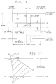
- Fig. 17 shows a V interval having an upper limit V1 and a lower limit V3, through which passes a trim curve polygon T having vertices T1, T2 and T3.
- Vertex T1 lies below the V interval V3-V1
- vertex T3 lies within the current V interval
- vertex T2 lies above the current V interval.
- the trim curve polygon T' clipped to the current V interval V3-V1, consists of the vertices T1A, T1B, T2A, T3 and T3A.
- the vertex information for this clipped trim curve polygon is stored as fifteen words in section 622 of local memory 204, as shown in Fig. 7.
- the fifteen words consist of five groups of three words corresponding to the respective vertices T1A, T1B, T2A, T3 and T3A of the trim curve polygon T' clipped to the V interval V3-V1.
- Vertices T1A, T1B, T2A, T3 and T3A are all classified as "draw" points, as indicated by an MDLOOP bit of 1 in the MOVDRW word for each of these vertices.
- the convexity flag (CONVEX) is not set to 1 (true)
- the resulting set of V-clipped UV coordinates may be tested for convexity.
- the results of these convexity tests may be represented by a flag VCONVEX which is initialised to 1 (true) prior to the transfer of the trim curve data from global memory 102 to local memory 204. If the V-clipped vertices are found to include more than one contour, or if any vortex fails the convexity test, then VCONVEX is set to 0 (false). If CONVEX is true or VCONVEX is false, subsequent convexity tests may be skipped. Alternatively, the flag VCONVEX may be set equal to the flag CONVEX and no convexity tests performed.
- the V interval loop initialises a quantity NSU, indicating the number of U spans to be processed, at NU - KU, where NU represents the U dimension of the control point matrix 310 and KU indicates the K order (1014). Also at this time, a quantity U2, indicating the upper limit of the U span being processed, is initialised at UKNOT (KU), and the flag UFRST, indicating the first U interval of the current U span, is set equal to 1.
- the U span loop which processes successive U spans defined by sequential pairs of U knots (U1, U2), where U2 is greater than U1, is shown in Fig. 11.
- the span lower limit U1 is set equal to the previous upper limit U2
- the new span upper limit U2 is set equal to UKNOT (NU - NSU + 1)
- UR indicating the remaining portion of the current U span awaiting processing, is set equal to U2 - U1 (1102).
- the span upper limit U2 is then compared with the span lower limit U1 (1104) to determine whether a proper U span has been defined. If not, processing jumps to step 1120, skipping intervening steps, in preparation for another iteration for the next U span.
- the set of trim curve segments currently stored in section 622 of local memory 204 is examined to identify the segments which also intersect the U span bounded by U1 and U2 (1106).
- the index of the first point of the first UV vector intersecting the current USPAN is stored as USPN1 and the index of the end (2nd) point of the last UV vector intersecting the current USPAN is stored as USPN2.
- the flag UVIS is set equal to 1 and the U interval step size USTEP is computed based on the U tessellation vector and the surface approximation attributes (1110). Otherwise, the flag UVIS is set equal to 0, and a default step size USTEP equal to the range UR of the current U span (equals U2 - U1) is selected (1112).
- the index NSU is decremented (1120) and compared with 0 (1122) to determine whether all of the U spans have been processed. If so, the U span loop is terminated (1124). Otherwise, processing returns to step 1102 for another iteration of the portion of the U span loop comprising steps 1102 to 1122.
- the U interval loop starts with the evaluation of the U dependence of the surface based on the V interval stack (section 4 in Figure 6) and the current value of U1.
- the derivatives of these values with respect to U and V are also computed at this point.
- These values are then used to determine the corresponding Cartesian coordinates (X, Y, and Z, top and bottom) and their derivatives (tangent vectors) with respect to both U and V.
- Surface normal vectors for the top and bottom of the current V interval are determined from the vector (cross) product of the tangent vectors.
- the magnitudes of these normal vectors are compared to the normal vector threshold (QMIN) for the current UV surface patch. If the magnitude of a normal vector is less than this threshold value, the normal vector is replaced with a normal vector from an adjacent vertex.
- QMIN normal vector threshold
- the dot product of the top normal vector with itself is then calculated (1222) (Fig. 12B) and compared with the QMIN for that span (1224). If the dot product exceeds QMIN, the flag TNRM is set to 1 (1226); otherwise it is set to 0 (1228).
- the normal vector to the UV surface at that point is then computed as the cross product of the U and V tangent vectors corresponding to the U and V derivatives (1232).
- the dot product of the bottom normal vector with itself is then computed (1234) and compared with QMIN for the current U span (1236). If the dot product is greater than QMIN, the flag BNRM is set to 1 (1238); otherwise it is set to 0 (1240). If BNRM is 1 and TNRM is 0 (1242), the top normal vector is set equal to the bottom normal vector and the flag TNRM set to 1 (1244). If on the other hand BNRM is 0 and TNRM is 1 (1246), the bottom normal vector is set equal to the top normal vector and the flag BNRM set equal to 1 (1248).
- the flag PEND is set equal to 1 (1258); otherwise the flag PEND is checked to determine whether it is set at 0 (1252). If it is not, the previously saved X Y and Z coordinates and normal vector components are used for the top right and bottom right corners of the current UV rectangle (1256). Otherwise, a unit vector pointing along the Z axis is selected for both the top right and bottom right normal vectors (1254). Upon completion of this step, as well as upon completion of step 1242, 1244 or 1248, the flag PEND is checked to determine whether it is set at 0 (1260). If so, the top and bottom normal vectors are saved for possible later use and the flag PEND set to 0 (1262).
- the U interval loop is entered N + 1 times, each time generating X, Y and Z coordinates and X, Y and Z normal vector components for top and bottom V interval values V1 and V3 and right U interval value U1.
- the loop is entered N + 1 times because there are N + 1 values defining the beginning and ending points of N U intervals
- QT and QB may be indicated generically as QT and QB, where T stands for top, B stands for bottom, and Q stands for X, Y, Z, XN, YN or ZN.
- the flag UFRST is again checked to determine whether this is the first pass through the U interval loop for the current U span (1264). If it is, then the flag UFRST is reset to 0 (1280) as a preliminary to terminating this pass through the loop. If this is not the first pass through the U interval loop for the current U span, then the trim curve polygon, which has previously been clipped to the current V interval, is further clipped to the UV rectangle formed by the intersection of the V interval with the current U interval (272).
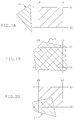
- the result of this UV clipping may be either an empty rectangle if the trimming region does not intersect the UV rectangle (Fig. 18), a full rectangle if the trimming region completely includes the UV rectangle (Fig. 19), or an irregular polygon (Fig. 20). (In Figs.
- the trim polygons are shown in their unclipped form, although in actuality they have been clipped to the V interval at this point).
- the X, Y and Z coordinates and normal vector components are calculated for each vertex of the polygon so formed, in a manner to be described further below (1274), and this vertex data is sent to the polygon processor.
- the flag ULAST is then tested to determine whether this is the last pass through the U interval loop for the current U span (1278). If so, the U interval loop is ended (1288). Otherwise, the lower limit U3 and upper limit U1 of the current U interval and remaining range UR of the U span are updated in preparation for another pass through the U interval loop (1282). The range UR is then tested to see whether it is greater than 0 (1284). If it is, then the routine returns to step 1202 for another pass through the loop. Otherwise, the upper limit U1 for the current U interval is set equal to the upper limit U2 for the span, and the flag ULAST set equal to 1, before returning to step 1202 (1286).
- the resulting UV polygon may be concave and is processed by the drawing and shading processors 106 in a manner which supports concave polygons.
- the concave polygon processor do not as such form part of the present invention, a suitable such concave polygon processor is disclosed in EP -A- 0425189.
- the coordinates and normal vectors for points on the edges and interior of a UV rectangle may be approximated by linear or bilinear interpolation between the corners.
- This approximation will benefit the performance of the system because bilinear interpolation requires fewer operations than evaluation of the NURBS equations for these points.
- This approximation will be accurate as long as the interpolated quadrilaterals are nearly flat, a condition which is also required by the corresponding area fill operations. This condition may be assured by appropriate choices of the surface approximation control values or quality factors.
- These lists may be concatenated one after the other following the list of trim curve vertices in local memory 204. These lists will often be empty and rarely contain more than one or two entries. After creating each list, the contents of each list are sorted by increasing value.
- a new vertex is created where the vector crosses the boundary.
- the MOVDRW word associated with each new vertex is assigned the same direction flags (NSDIR, NSDR2, EWDIR, EWDR2) as the preceding vertex, as well as the same values of the VTOP and VBOT flags.
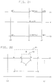
- the flags VBOT, VTOP, ULFT and URGT of each vertex obtained from clipping the trim curves to the current U interval are tested to identify vertices which lie on the boundaries of the UV rectangle defined by the current U interval and current V interval. If a vertex does not lie on any boundary of the UV rectangle, then the XYZ coordinates and normal vector of the vertex are determined through bilinear interpolation between the values computed for the corners of the UV rectangle. In this case, the bilinear interpolation is accomplished in three stages (Fig.
- QTOP(U) (QTL*(U1 - U) + QTR*(U - U3))*DU
- QBOT(U) (QBL*(U1 - U) + QBR*(U - U3))*DU
- Q(U,V) (QTOP*(V - V3) + QBOT*(V1 - V))*DV
- Q represents each of the six values defined by the XYZ coordinates and normal vector.
- the preceding vertex is also checked for its location with respect to the boundaries of the UV rectangle. If the current and preceding vertices both fall on a common boundary, then the corresponding list of edge crossing points is searched for any points which fall between the current and preceding vertices. The XYZ coordinates and normal vectors are then generated for each such point using the appropriate single-stage interpolation formula.
- Subareas ABCD and EFGHI may have resulted from clipping two trim polygons P1 and P2 (together defining a doughnut-shaped region between the two polygon boundaries) to the V interval V3-V1.
- the first subarea is determined by four vertices labelled as (A,B,C,D), and the second subarea is determined by the five vertices labelled as (E,F,G,H,I).
- the U parameter values associated with vertices (G) and (H) i.e.
- UG and UH will be placed in the list of VTOP crossing points. Prior to calculating the XYZ coordinates and normal vector for vertex (C), this list is scanned, leading to the introduction of vertices (G) and (H) in that order. As a result, the first subarea will be represented by six vertices (A,B,G,H,C,D).
- the vector representing line (G-H) in screen space will no longer be colinear with the vector representing line (B-C), leading to residual (artifact) pixels when the pixels along the (G-H) boundary of the second subarea are subtracted from the pixels along the (B-C) boundary of the first subarea.
Landscapes
- Engineering & Computer Science (AREA)
- Computer Graphics (AREA)
- Physics & Mathematics (AREA)
- General Physics & Mathematics (AREA)
- Theoretical Computer Science (AREA)
- Image Generation (AREA)
- Digital Computer Display Output (AREA)
Applications Claiming Priority (2)
| Application Number | Priority Date | Filing Date | Title |
|---|---|---|---|
| US62096590A | 1990-11-30 | 1990-11-30 | |
| US620965 | 1990-11-30 |
Publications (2)
| Publication Number | Publication Date |
|---|---|
| EP0488563A2 true EP0488563A2 (de) | 1992-06-03 |
| EP0488563A3 EP0488563A3 (en) | 1993-11-03 |
Family
ID=24488144
Family Applications (1)
| Application Number | Title | Priority Date | Filing Date |
|---|---|---|---|
| EP19910310634 Withdrawn EP0488563A3 (en) | 1990-11-30 | 1991-11-19 | Method and apparatus for rendering trimmed parametric surfaces |
Country Status (3)
| Country | Link |
|---|---|
| US (1) | US5488684A (de) |
| EP (1) | EP0488563A3 (de) |
| JP (1) | JPH07120433B2 (de) |
Families Citing this family (48)
| Publication number | Priority date | Publication date | Assignee | Title |
|---|---|---|---|---|
| JPH07282117A (ja) * | 1994-04-08 | 1995-10-27 | Ricoh Co Ltd | 自由曲面生成方法及び自由曲面形状の制御方法 |
| US5864342A (en) * | 1995-08-04 | 1999-01-26 | Microsoft Corporation | Method and system for rendering graphical objects to image chunks |
| US5886701A (en) * | 1995-08-04 | 1999-03-23 | Microsoft Corporation | Graphics rendering device and method for operating same |
| US5842004A (en) | 1995-08-04 | 1998-11-24 | Sun Microsystems, Inc. | Method and apparatus for decompression of compressed geometric three-dimensional graphics data |
| US5808617A (en) * | 1995-08-04 | 1998-09-15 | Microsoft Corporation | Method and system for depth complexity reduction in a graphics rendering system |
| US5870097A (en) | 1995-08-04 | 1999-02-09 | Microsoft Corporation | Method and system for improving shadowing in a graphics rendering system |
| US5852443A (en) * | 1995-08-04 | 1998-12-22 | Microsoft Corporation | Method and system for memory decomposition in a graphics rendering system |
| US5949428A (en) * | 1995-08-04 | 1999-09-07 | Microsoft Corporation | Method and apparatus for resolving pixel data in a graphics rendering system |
| US5990904A (en) * | 1995-08-04 | 1999-11-23 | Microsoft Corporation | Method and system for merging pixel fragments in a graphics rendering system |
| US5977977A (en) * | 1995-08-04 | 1999-11-02 | Microsoft Corporation | Method and system for multi-pass rendering |
| US5828382A (en) * | 1996-08-02 | 1998-10-27 | Cirrus Logic, Inc. | Apparatus for dynamic XY tiled texture caching |
| US6639592B1 (en) * | 1996-08-02 | 2003-10-28 | Silicon Graphics, Inc. | Curve network modeling |
| US6906718B1 (en) * | 1997-04-25 | 2005-06-14 | Microsoft Corporation | Method and system for efficiently evaluating and drawing NURBS surfaces for 3D graphics |
| US6173271B1 (en) | 1997-11-26 | 2001-01-09 | California Institute Of Technology | Television advertising automated billing system |
| US6262741B1 (en) | 1998-03-17 | 2001-07-17 | Prc Public Sector, Inc. | Tiling of object-based geographic information system (GIS) |
| US6144338A (en) * | 1998-03-17 | 2000-11-07 | Prc Public Sector. Inc. | Predictive drop and load algorithm for an object-based geographical information system |
| US6247019B1 (en) * | 1998-03-17 | 2001-06-12 | Prc Public Sector, Inc. | Object-based geographic information system (GIS) |
| US6404435B1 (en) * | 1998-04-03 | 2002-06-11 | Avid Technology, Inc. | Method and apparatus for three-dimensional alphanumeric character animation |
| US6661534B1 (en) * | 1998-09-16 | 2003-12-09 | Texas Instruments Incorporated | Selective screening for printing files in a page description language |
| JP2000112342A (ja) * | 1998-09-30 | 2000-04-21 | Pioneer Electronic Corp | 地図情報の処理方法 |
| US6304271B1 (en) * | 1999-02-05 | 2001-10-16 | Sony Corporation | Apparatus and method for cropping an image in a zooming graphical user interface |
| US6512522B1 (en) | 1999-04-15 | 2003-01-28 | Avid Technology, Inc. | Animation of three-dimensional characters along a path for motion video sequences |
| US6683620B1 (en) * | 1999-04-21 | 2004-01-27 | Autodesk, Inc. | Relational modeling of trimmed nurbs surfaces |
| US6920415B1 (en) * | 2000-04-12 | 2005-07-19 | California Institute Of Technology | Method of trimming a representation of an object surface comprising a mesh of tessellated polygons and related system |
| US7145564B1 (en) * | 2000-06-01 | 2006-12-05 | Ati International, Srl | Method and apparatus for tessellation lighting |
| US6996505B1 (en) | 2000-06-21 | 2006-02-07 | Raindrop Geomagic, Inc. | Methods, apparatus and computer program products for automatically generating nurbs models of triangulated surfaces using homeomorphisms |
| US7245299B2 (en) * | 2003-05-12 | 2007-07-17 | Adrian Sfarti | Bicubic surface real-time tesselation unit |
| USRE42534E1 (en) | 2000-07-28 | 2011-07-12 | Adrian Sfarti | Bicubic surface real-time tesselation unit |
| US7414635B1 (en) * | 2000-08-01 | 2008-08-19 | Ati International Srl | Optimized primitive filler |
| US6624811B1 (en) * | 2000-08-31 | 2003-09-23 | Nvidia Corporation | System, method and article of manufacture for decomposing surfaces using guard curves and reversed stitching |
| US7280108B2 (en) * | 2000-12-11 | 2007-10-09 | Adrian Sfarti | Bicubic surface rendering |
| US6853373B2 (en) | 2001-04-25 | 2005-02-08 | Raindrop Geomagic, Inc. | Methods, apparatus and computer program products for modeling three-dimensional colored objects |
| US20030016233A1 (en) * | 2001-06-29 | 2003-01-23 | Bitflash Graphics, Inc. | Method and system for manipulation of graphics information |
| US20030020726A1 (en) * | 2001-06-29 | 2003-01-30 | Bitflash Graphics, Inc. | Method and system for displaying graphics information |
| US7518609B2 (en) * | 2005-05-27 | 2009-04-14 | The Boeing Company | System, method and computer program product for modeling a transition between adjoining surfaces |
| US7924294B2 (en) * | 2006-12-27 | 2011-04-12 | The Mathworks, Inc. | Polygon trimming using a modified azimuthal map projection |
| US8269770B1 (en) | 2008-02-29 | 2012-09-18 | Adobe Systems Incorporated | Tessellation of trimmed parametric surfaces by walking the surface |
| CN102110181A (zh) * | 2009-12-28 | 2011-06-29 | 鸿富锦精密工业(深圳)有限公司 | 自由曲面面积计算系统及方法 |
| US9177420B2 (en) * | 2010-10-25 | 2015-11-03 | Autodesk, Inc. | Intuitive shape control for boundary patches |
| US9142060B2 (en) | 2012-08-30 | 2015-09-22 | Qualcomm Incorporated | Computation reduced tessellation |
| US9076260B2 (en) | 2012-08-30 | 2015-07-07 | Qualcomm Incorporated | Stitching for primitives in graphics processing |
| US9082204B2 (en) | 2012-08-30 | 2015-07-14 | Qualcomm Incorporated | Storage structures for stitching primitives in graphics processing |
| US9965887B2 (en) | 2013-03-05 | 2018-05-08 | Autodesk, Inc. | Technique for mapping a texture onto a three-dimensional model |
| US9595135B2 (en) * | 2013-03-05 | 2017-03-14 | Autodesk, Inc. | Technique for mapping a texture onto a three-dimensional model |
| JP6158735B2 (ja) * | 2014-03-28 | 2017-07-05 | 京セラドキュメントソリューションズ株式会社 | 画像形成装置、描画処理方法及びプログラム |
| US10339266B2 (en) * | 2016-02-16 | 2019-07-02 | Board Of Regents Of The University Of Texas Systems | Mechanisms for constructing spline surfaces to provide inter-surface continuity |
| US9984496B1 (en) | 2016-08-23 | 2018-05-29 | Bentley Systems, Incorporated | Technique for compact and accurate encoding trim geometry for application in a graphical processing unit |
| US10810795B2 (en) * | 2018-06-13 | 2020-10-20 | S-Splines, LLC | Isogeometric analysis and computer-aided design using S-splines |
Family Cites Families (5)
| Publication number | Priority date | Publication date | Assignee | Title |
|---|---|---|---|---|
| US4760548A (en) * | 1986-06-13 | 1988-07-26 | International Business Machines Corporation | Method and apparatus for producing a curve image |
| US4999789A (en) * | 1987-02-05 | 1991-03-12 | Hewlett-Packard Co. | Method and apparatus for trimming B-spline descriptions of patches in a high performance three dimensional graphics system |
| US5226115A (en) * | 1987-02-05 | 1993-07-06 | Hewlett Packard Company | Method and apparatus for trimming B-spline descriptions of patches in a high performance three dimensional graphics system |
| US4912659A (en) * | 1987-10-30 | 1990-03-27 | International Business Machines Corporation | Parallel surface processing system for graphics display |
| JPH0776991B2 (ja) * | 1989-10-24 | 1995-08-16 | インターナショナル・ビジネス・マシーンズ・コーポレーション | Nurbsデータ変換方法及び装置 |
-
1991
- 1991-11-19 EP EP19910310634 patent/EP0488563A3/en not_active Withdrawn
- 1991-11-21 JP JP3331628A patent/JPH07120433B2/ja not_active Expired - Lifetime
-
1994
- 1994-09-23 US US08/311,701 patent/US5488684A/en not_active Expired - Fee Related
Also Published As
| Publication number | Publication date |
|---|---|
| JPH07120433B2 (ja) | 1995-12-20 |
| JPH04287292A (ja) | 1992-10-12 |
| EP0488563A3 (en) | 1993-11-03 |
| US5488684A (en) | 1996-01-30 |
Similar Documents
| Publication | Publication Date | Title |
|---|---|---|
| US5488684A (en) | Method and apparatus for rendering trimmed parametric surfaces | |
| US7081895B2 (en) | Systems and methods of multi-pass data processing | |
| US5307450A (en) | Z-subdivision for improved texture mapping | |
| US5963210A (en) | Graphics processor, system and method for generating screen pixels in raster order utilizing a single interpolator | |
| US7027050B1 (en) | 3D computer graphics processing apparatus and method | |
| US7148890B2 (en) | Displacement mapping by using two passes through the same rasterizer | |
| JP3344597B2 (ja) | グラフィック画像をテッセレーション化する方法および装置 | |
| US7969436B1 (en) | System, method and computer program product for transforming a polynomial equation from a coordinate frame of one tile to a coordinate frame of another tile at a finer level of a hierachy | |
| US4888712A (en) | Guardband clipping method and apparatus for 3-D graphics display system | |
| US4609917A (en) | Three-dimensional display system | |
| US6674430B1 (en) | Apparatus and method for real-time volume processing and universal 3D rendering | |
| JP2769427B2 (ja) | 一連のグラフィック・プリミティブ用のデータを処理するための方法 | |
| US5278949A (en) | Polygon renderer which determines the coordinates of polygon edges to sub-pixel resolution in the X,Y and Z coordinates directions | |
| EP0723689B1 (de) | Direktes rendering von texturierten höhenfeldern | |
| JP3968063B2 (ja) | グラフィックオブジェクトを画像チャンクにレンダリングして、画像層を表示画像に組み合わせる方法及びシステム | |
| US5867166A (en) | Method and system for generating images using Gsprites | |
| US5276783A (en) | Tessellating complex polygons in modeling coordinates | |
| US7952579B1 (en) | System, method and computer program product for geometrically transforming geometric objects | |
| US6292192B1 (en) | System and method for the direct rendering of curve bounded objects | |
| KR20050030595A (ko) | 화상 처리 장치 및 그 방법 | |
| JPWO2000002165A1 (ja) | ポリゴンデータの生成方法及び、これを用いた画像表示装置 | |
| US5555356A (en) | System and method for generating a trimmed parametric surface for display on a graphic display device | |
| EP1519317B1 (de) | Tiefen-basiertes Antialiasing | |
| US5719599A (en) | Method and apparatus for efficient digital modeling and texture mapping | |
| EP0548629A2 (de) | Festkörperabschneidungsvorrichtung und Architektur für Festkörperabschneidung und Querschnittanzeige mit Tiefenpuffer |
Legal Events
| Date | Code | Title | Description |
|---|---|---|---|
| PUAI | Public reference made under article 153(3) epc to a published international application that has entered the european phase |
Free format text: ORIGINAL CODE: 0009012 |
|
| AK | Designated contracting states |
Kind code of ref document: A2 Designated state(s): DE FR GB |
|
| PUAL | Search report despatched |
Free format text: ORIGINAL CODE: 0009013 |
|
| AK | Designated contracting states |
Kind code of ref document: A3 Designated state(s): DE FR GB |
|
| STAA | Information on the status of an ep patent application or granted ep patent |
Free format text: STATUS: THE APPLICATION IS DEEMED TO BE WITHDRAWN |
|
| 18D | Application deemed to be withdrawn |
Effective date: 19940530 |